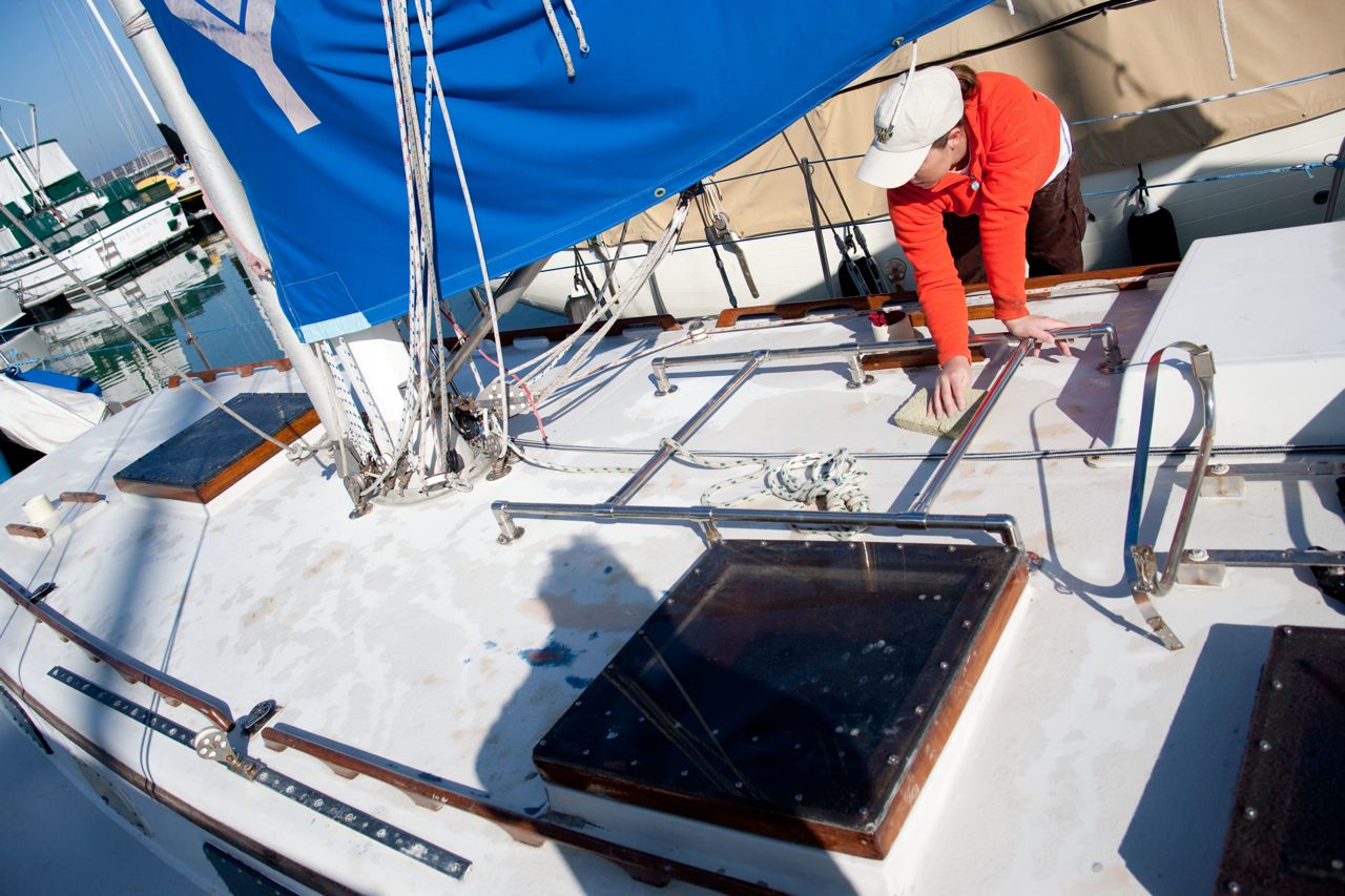
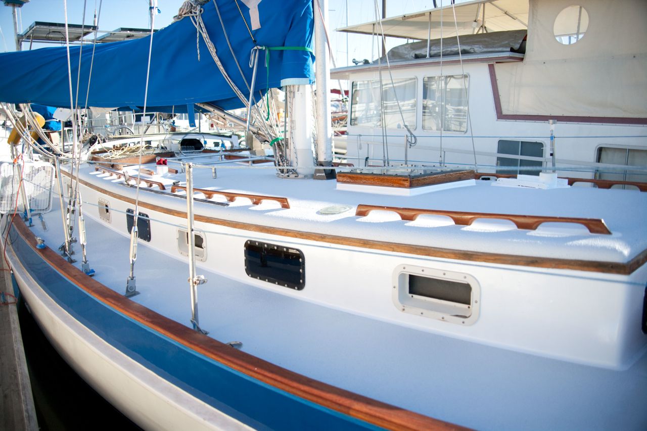
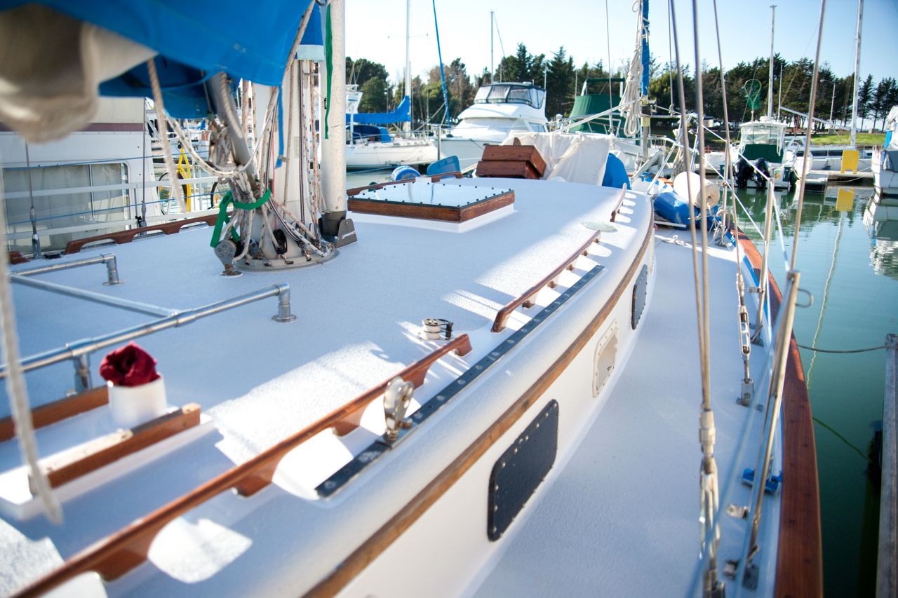
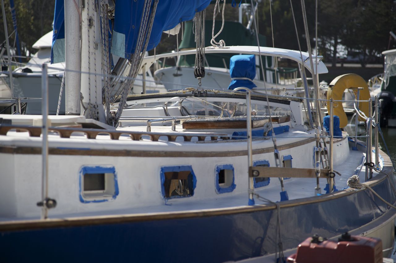
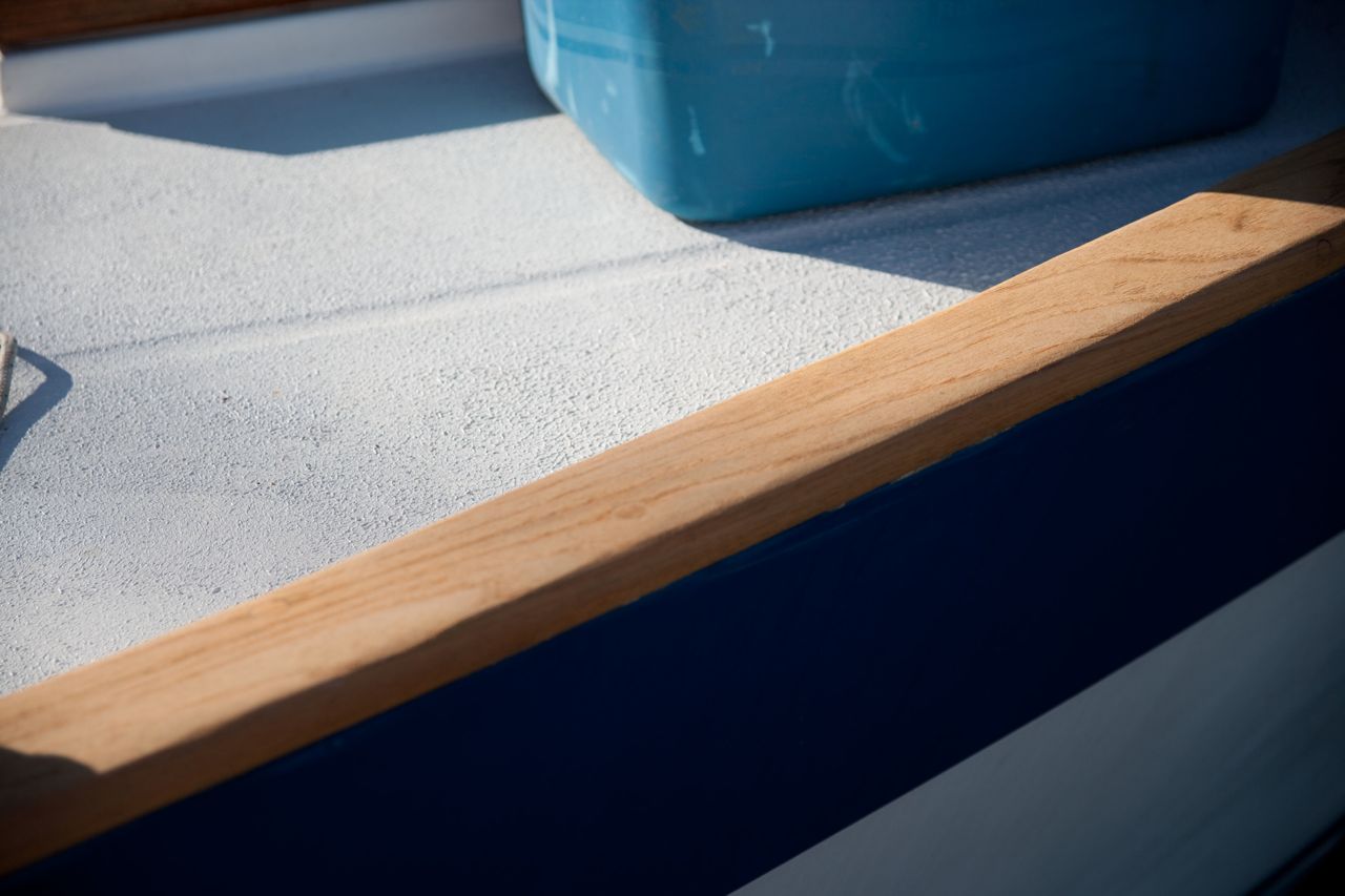
Ooh boy this has been a long time coming. I have been looking forward to this job more than any other, for the past year, because it is one of the few jobs that people walking down the dock can actually see and admire. Most everything else I do on the boat is hidden behind some panel and goes unseen and unsung.
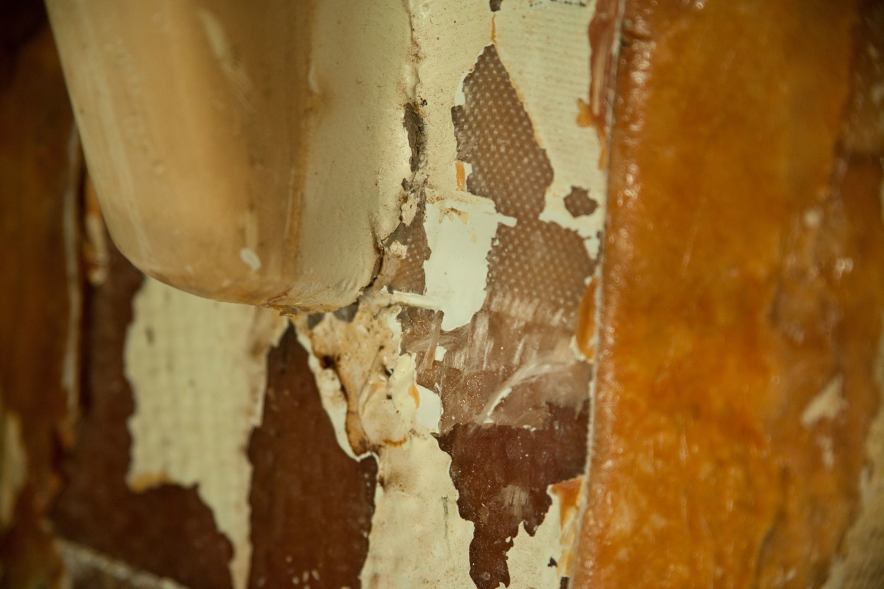
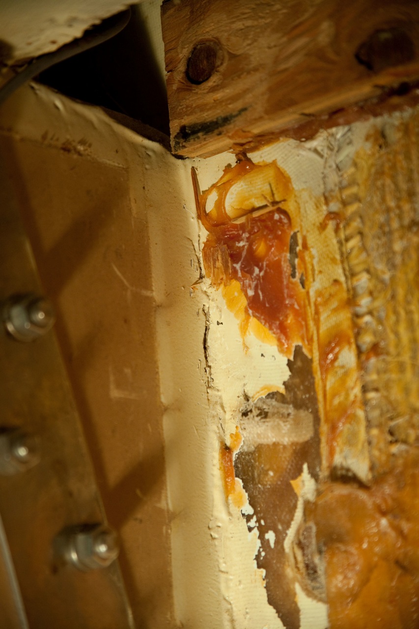
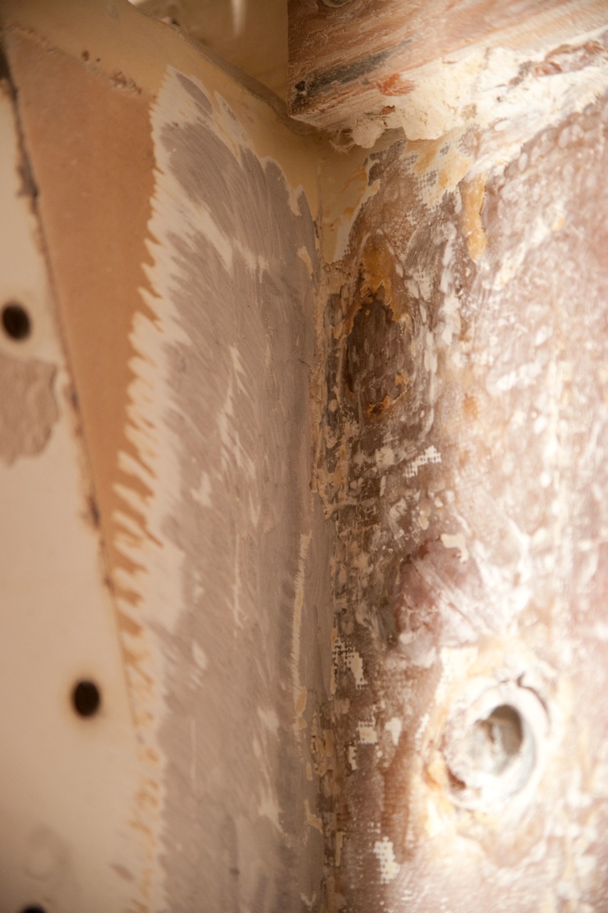
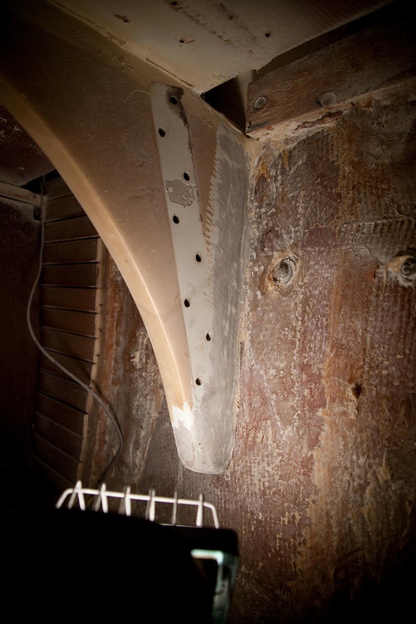
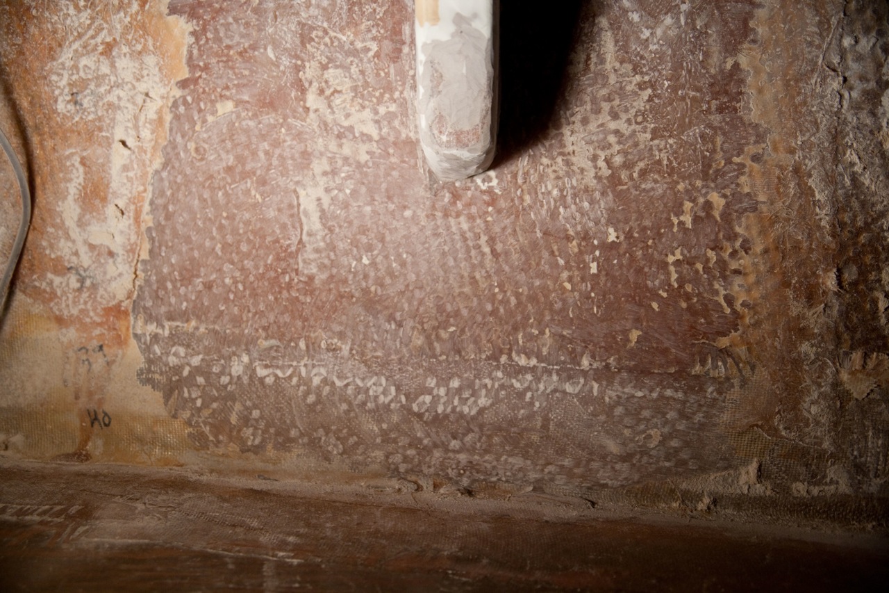
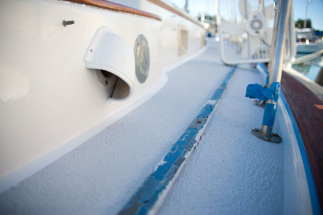
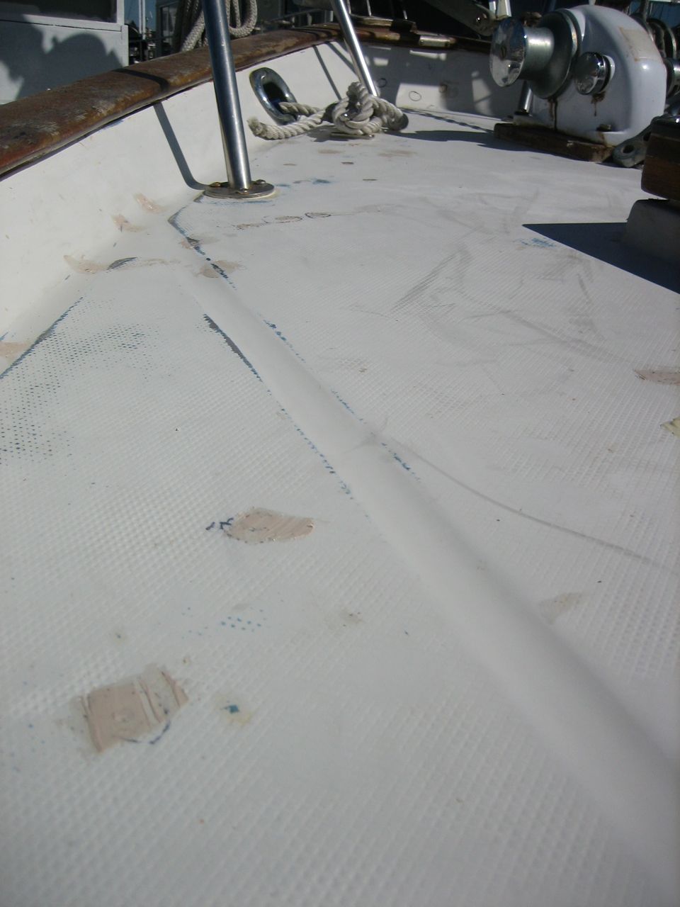
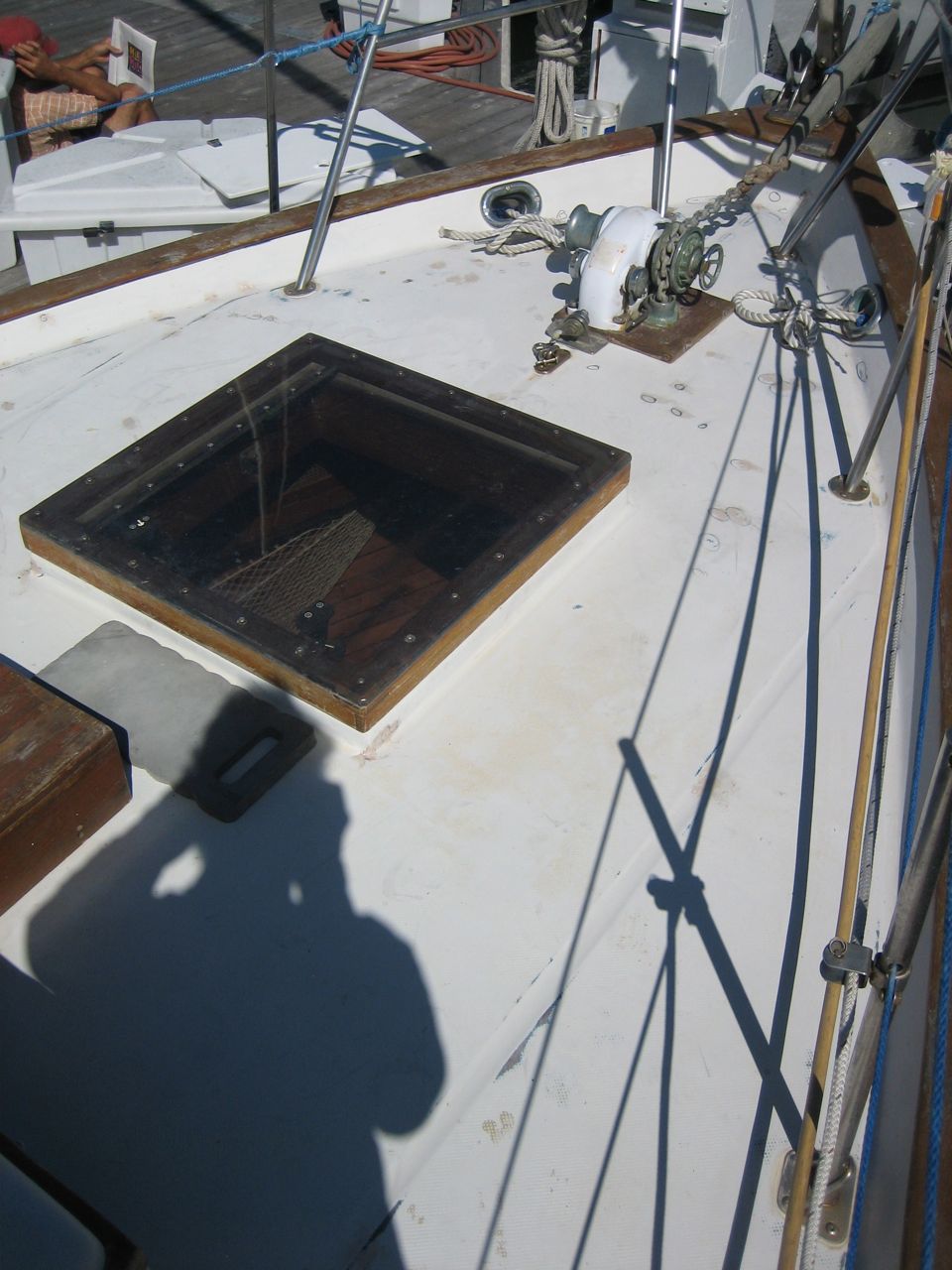
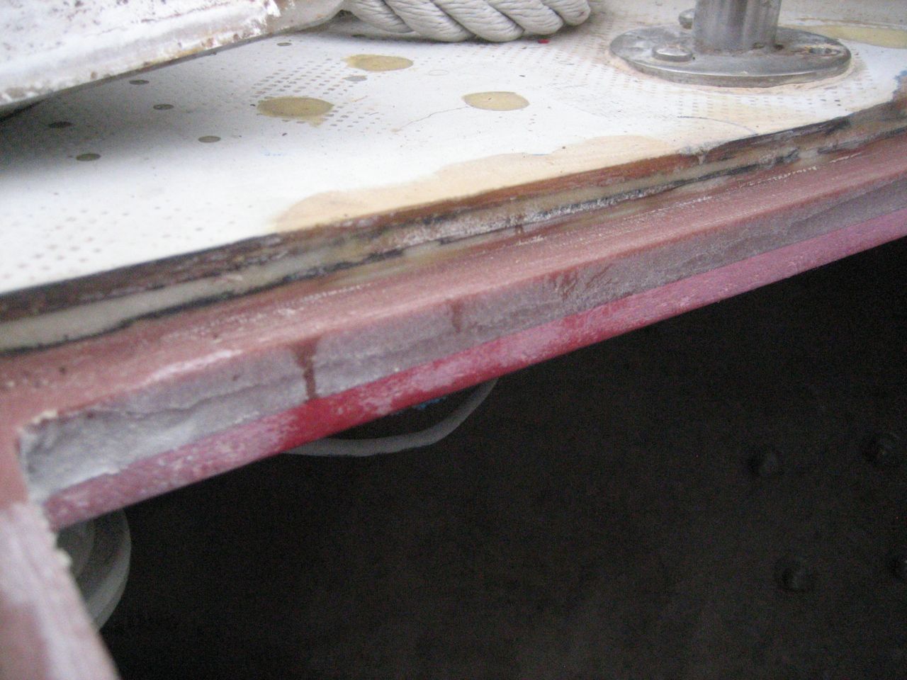
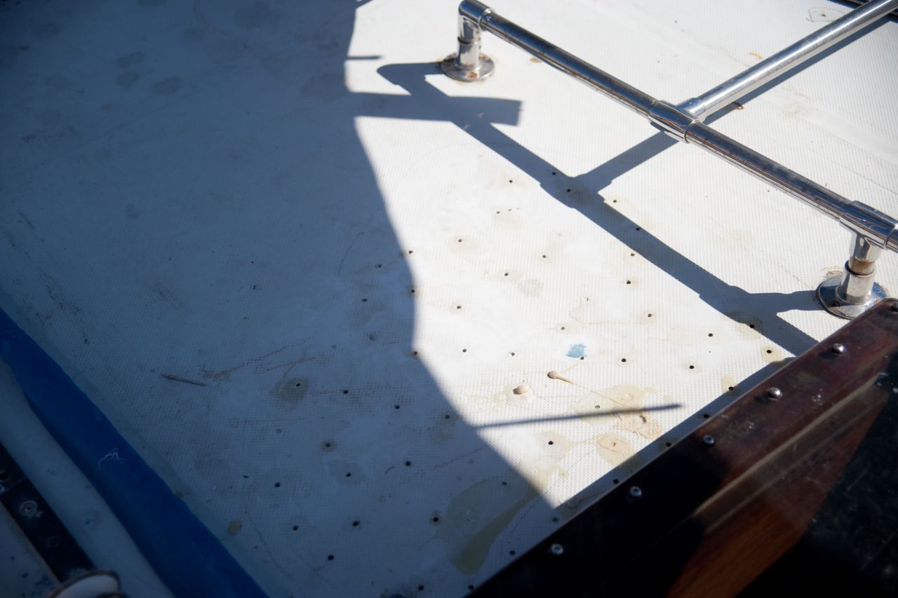
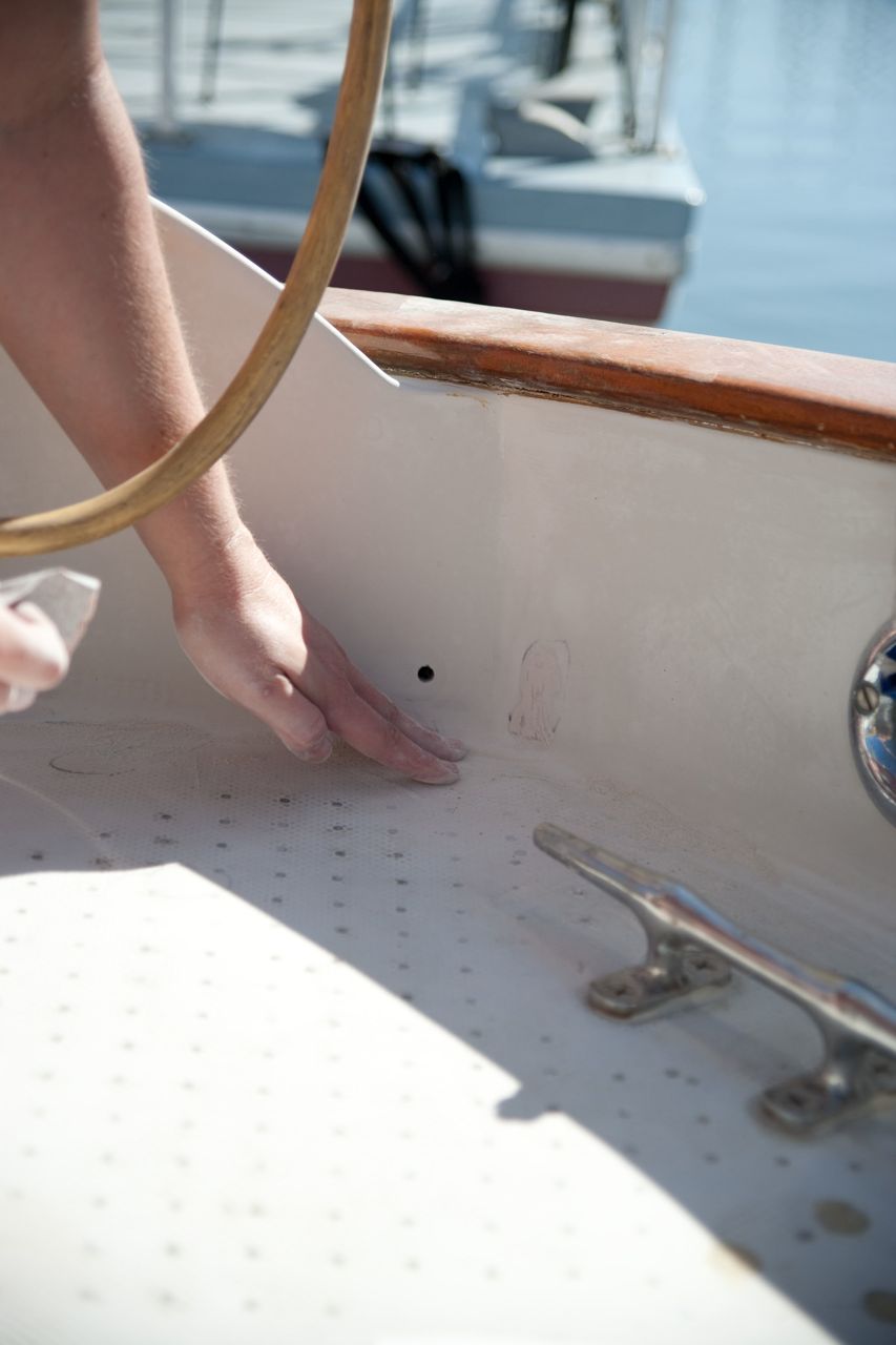
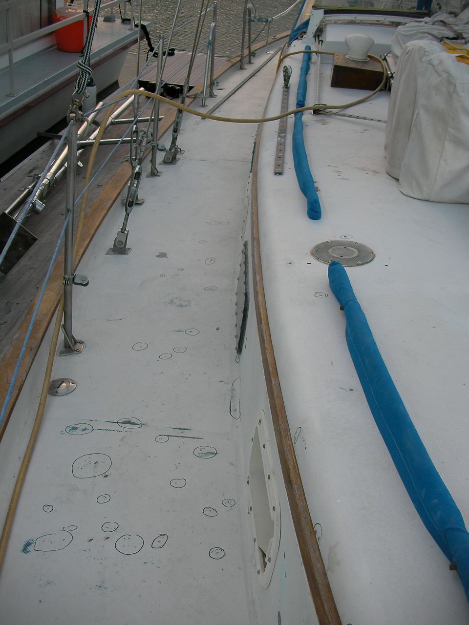
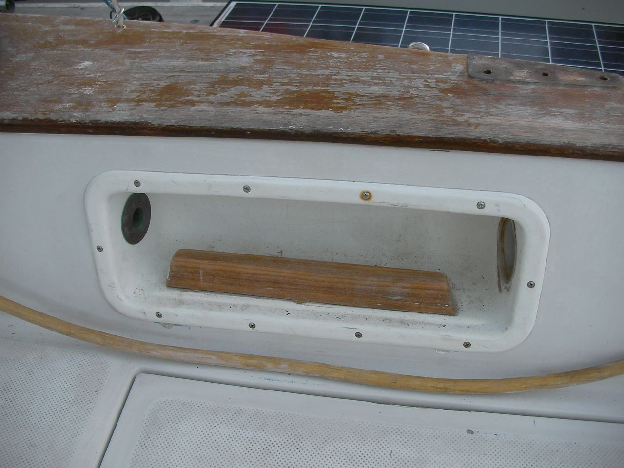
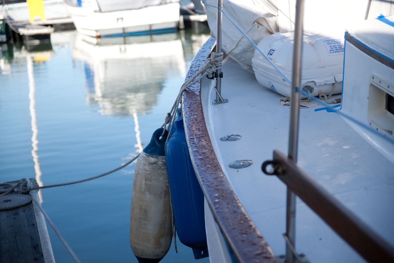
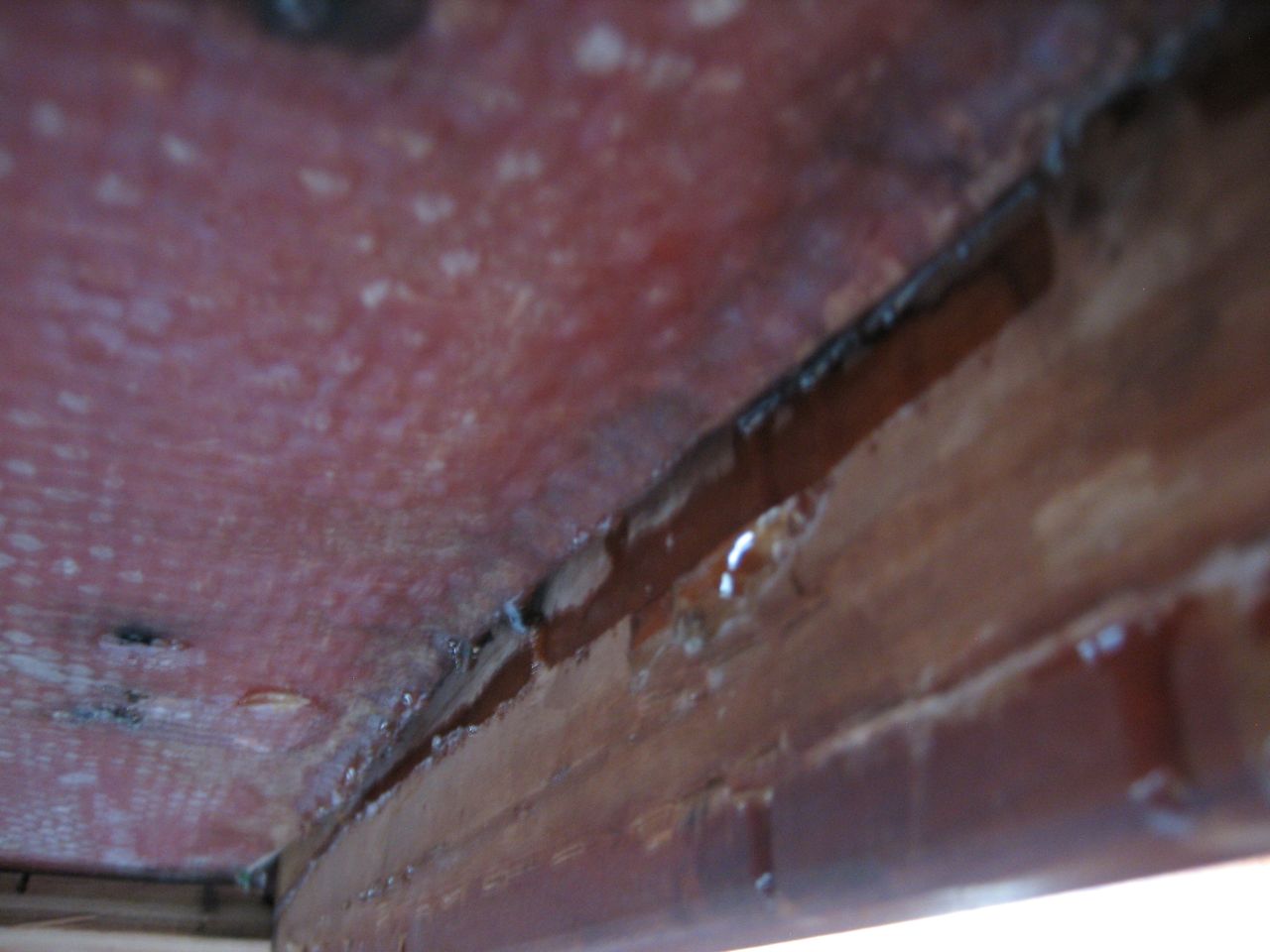
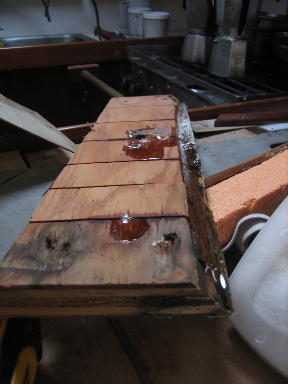
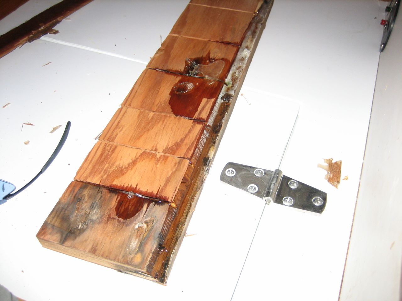
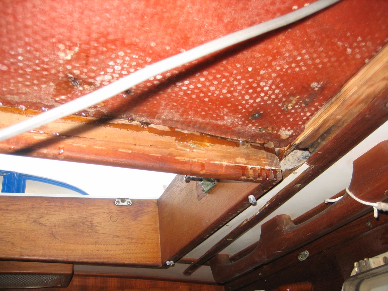
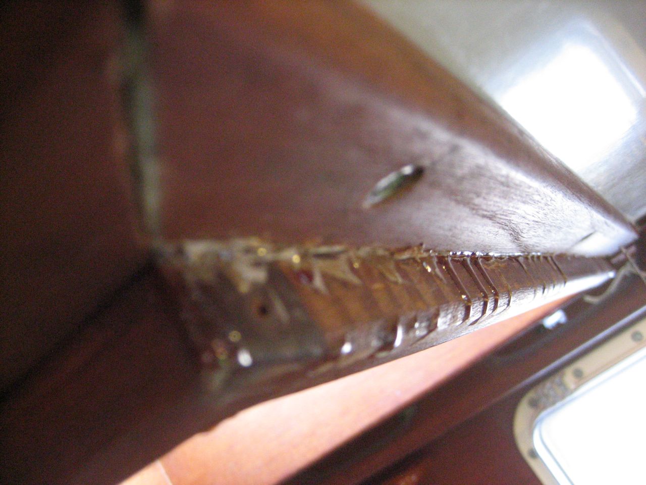
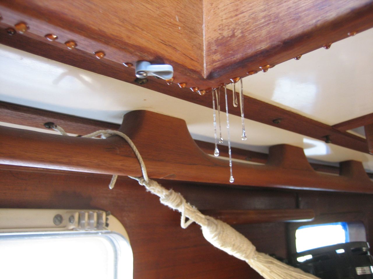
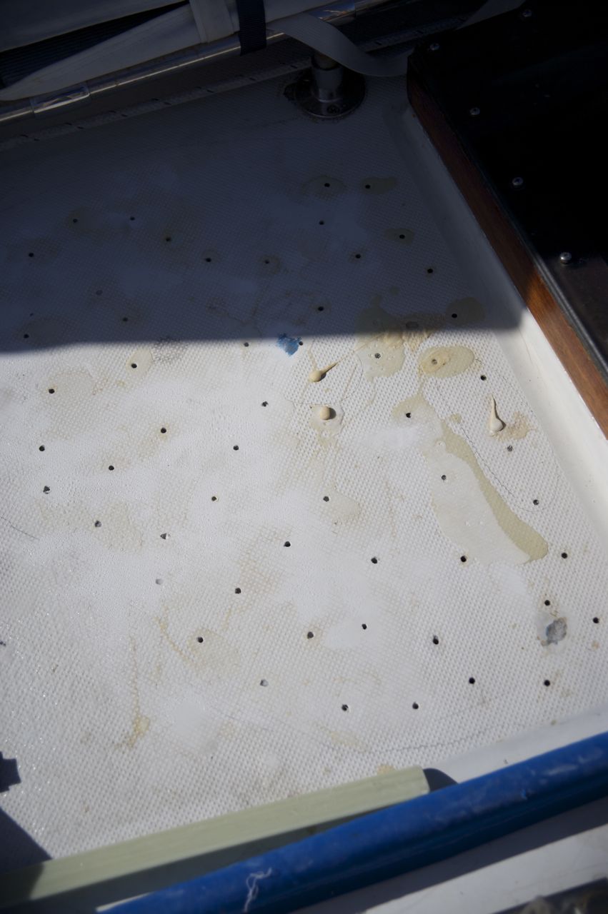
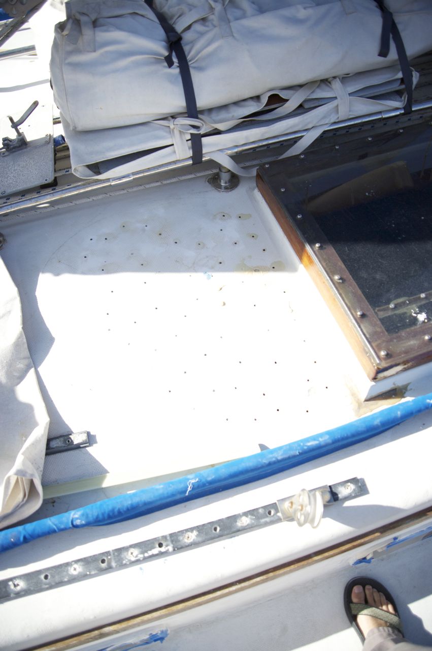
Since we bought the boat, the deck has become increasingly ugly. We made no attempts to keep errant epoxy or other crap from marring the surface; many spots have holes drilled for the purpose of repairing minor delamination; some areas jonny gooped over with plain epoxy in a failed attempt to fair the surface where there was some crack or hole. The final state of the deck before I started sanding it was undeniably shameful. Some might argue that appearances don’t matter and that our deck only looked ugly, but the truth is that there were cracks and holes all over the place that were admitting water into the balsa core and causing increasingly serious delamination (see my post regarding the delamination mess).
Since other projects have been so much higher priority, I have had a really long time to dream up how I was going to tackle this project. I went through a number of different options for which non-skid to use. For a few months I was planning on going the way of Wally, using a product called Ultra-Tuff. Fortunately, Wally’s boat Stella Blue happened to be in a marina less than 10 minutes away at the time, so I got in touch with him and went over to see for myself how it turned out. I have the utmost respect for Wally–he does the most meticulous and ridiculously successful work on his boat of anyone I know and his project pages have been invaluable to me–but I didn’t like the ultra-tuff that much. Largely because it was a sharp, fairly brittle feeling surface, and not too pretty. I definitely didn’t want to do the shake-sand-on-paint route, or the route of putting “microballoons” or some other such artificial sand in the paint and rolling it on, etc, because all of those decks that I have seen look very amateur, very DIY, and didn’t seem all that non-skid either.
All of those methods are still a hundred times better than our deck was before I touched it, and all perfectly adequate solutions. But I had about a year to plan this project to perfection, and since the sheer magnitude of this job is overwhelming, I needed to feel like I would be really excited and proud of the end result, or else my motivation would waver.
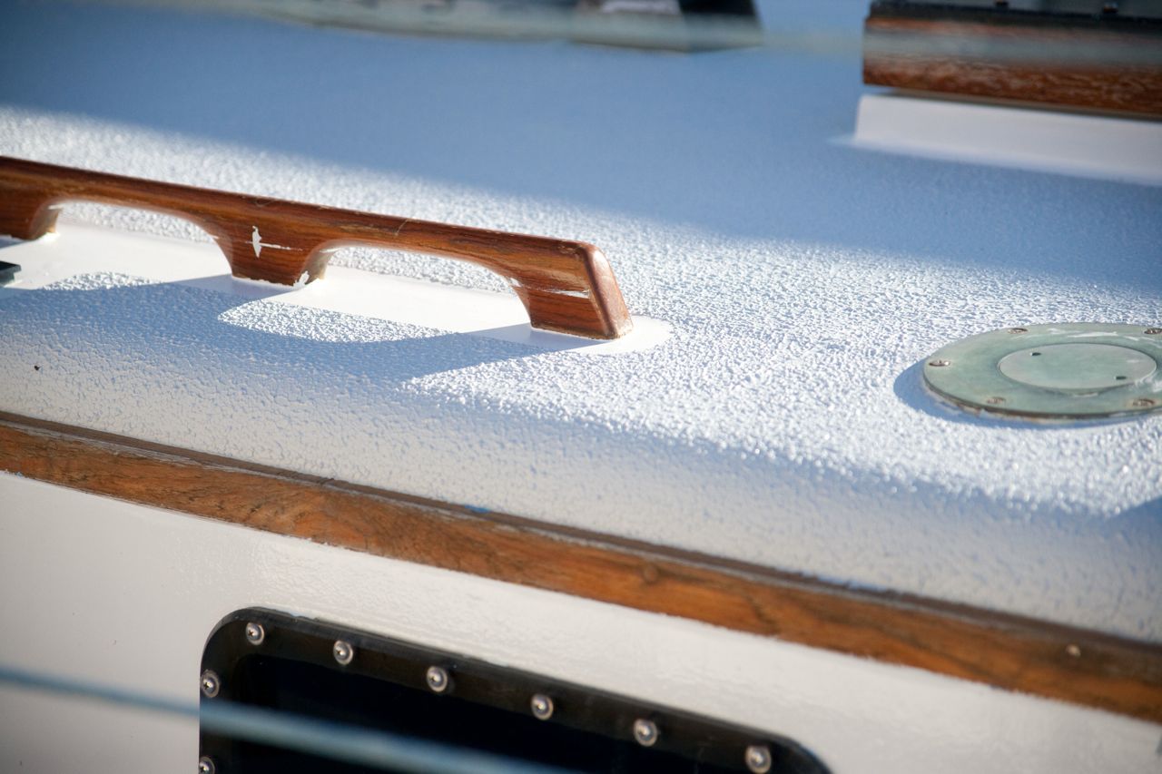
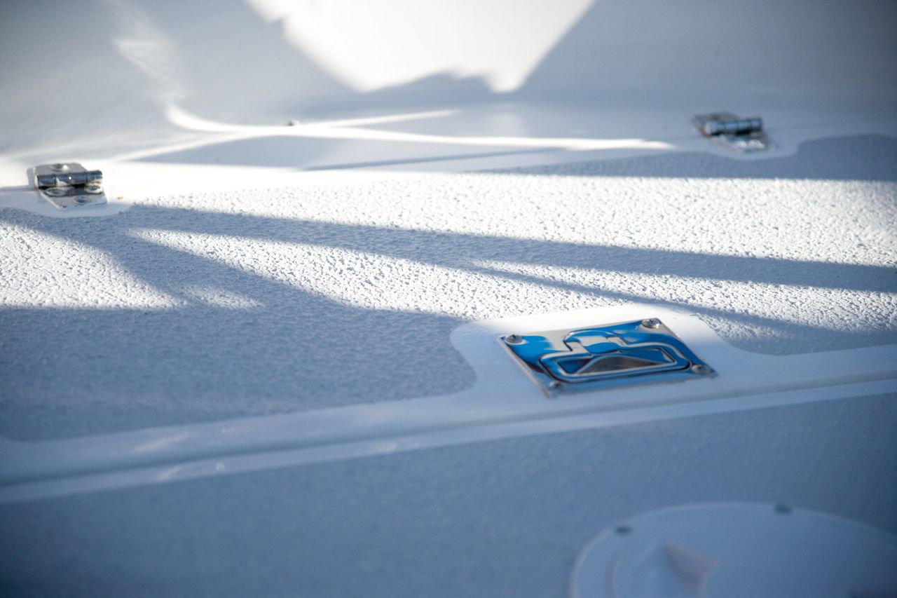
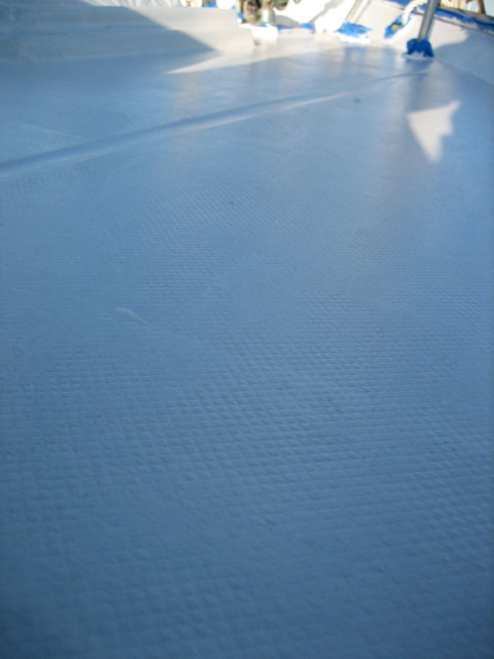
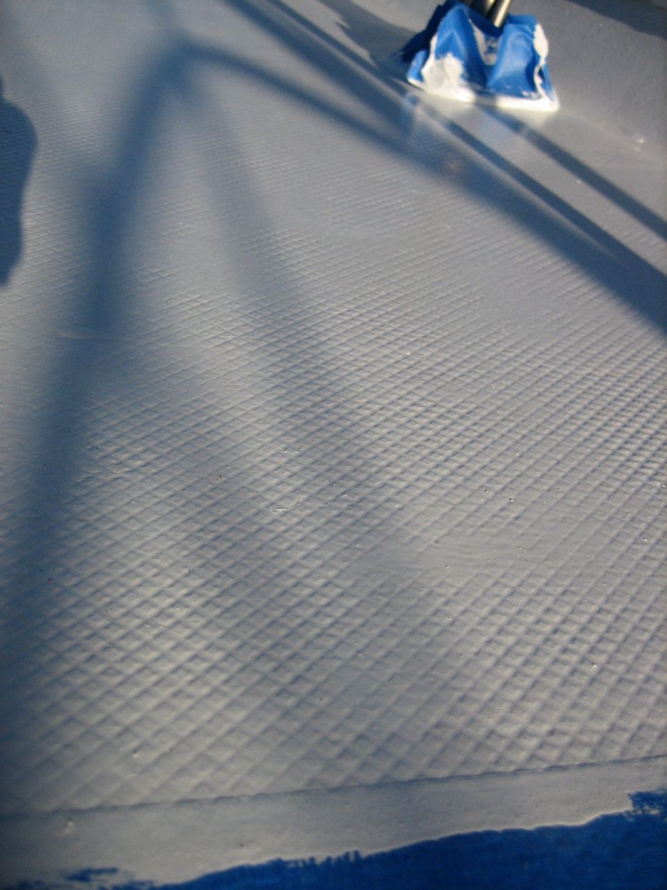
I ended up choosing a product called Kiwi-Grip, because of the ease of application, the ease of recoating when necessary, and the look of the finished surface (as viewed up-close on various web pages where I found references). It costs $100/gallon and you have to use a lot of it to get a really nice texture. I ended up using 2.25 gallons to do the entire boat.
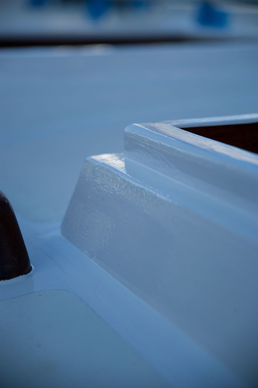
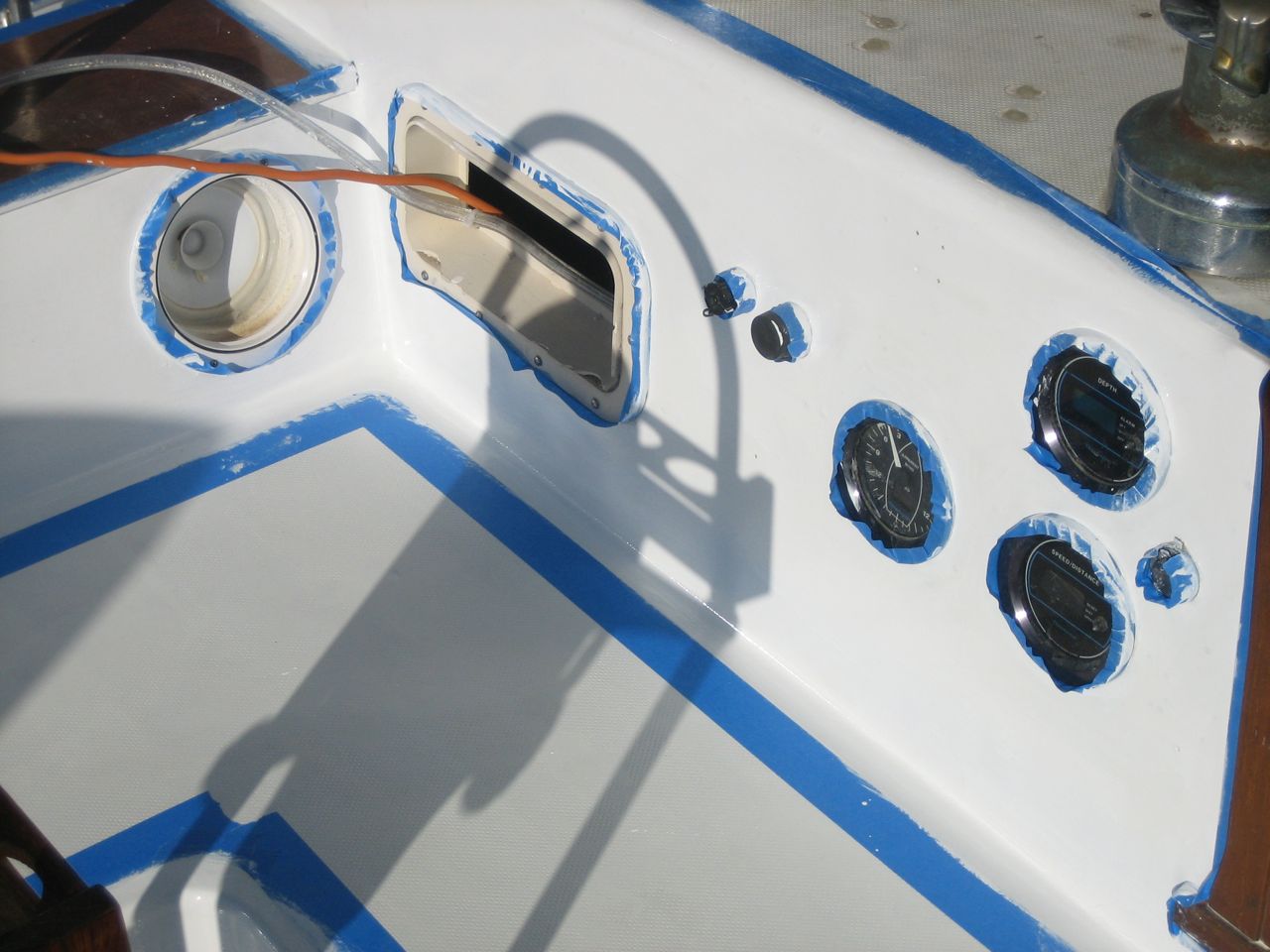
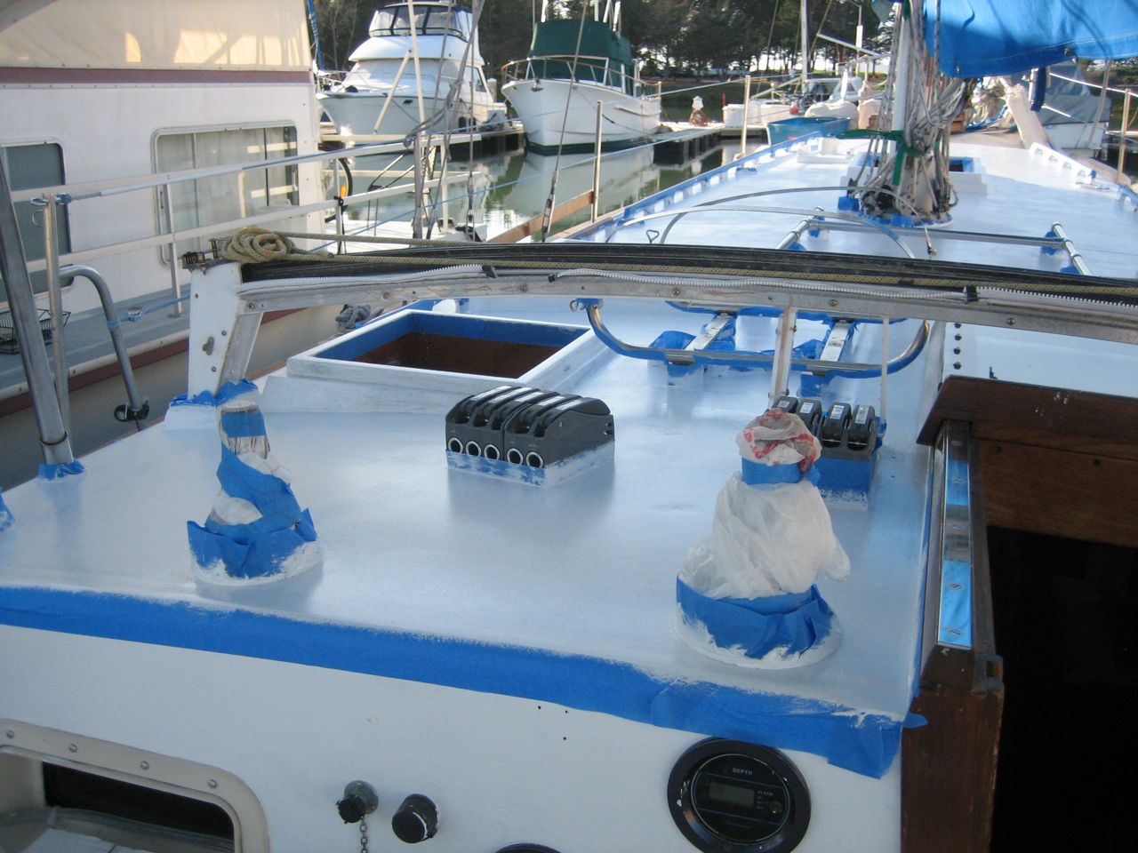
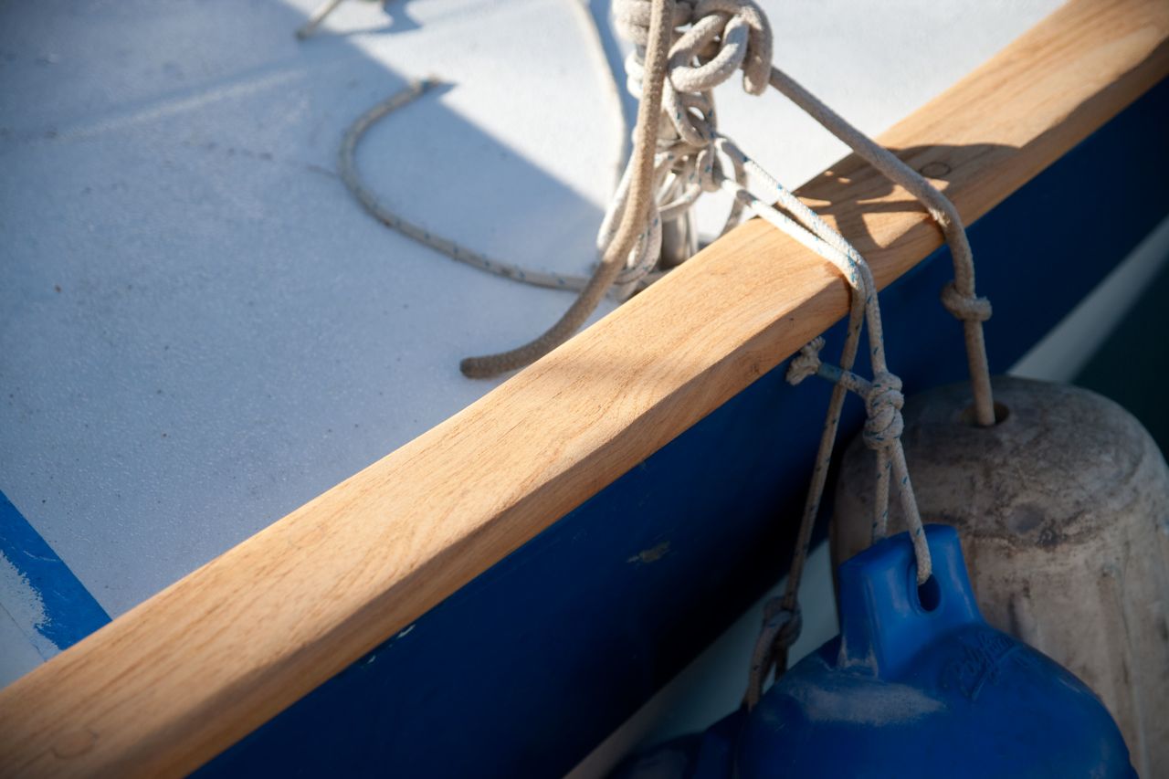
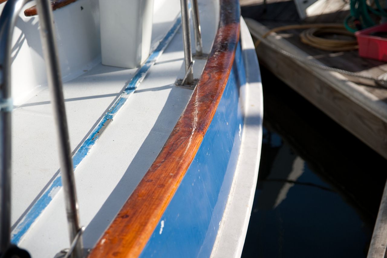
I elected to brush on a two-part polyurethane paint for all the non-non-skid (i.e. “skid”) areas. Usually this means the trim around the edges of hatches, the outside edge under the caprail, etc. Two-part polyurethane is synonymous with “linear polyurethane”, which I can abbreviate as LP, and that’s a hell of a lot easier to type from now on.
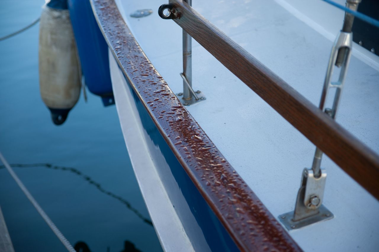
LP is harder to apply nicely than single-part polyurethane. The surface of it gels quickly, so you have to start painting and keep moving and you can’t go back and fix “mistakes”. For the professionals, “mistakes” refers to brush strokes that remain visible in the paint after it cures, instead of disappearing into a mirror-finish gloss that looks like it was sprayed on. For me, “mistakes” refers to long drips and runs and uneven gobs of paint, etc, in spots where I accidentally caught the brush on an edge, or couldn’t see the white-on-white paint dripping down, etc, and so my mistakes are very obvious. The good thing is that the mistakes don’t matter for the functionality. LP is a hell of a lot more durable and long-lasting than single-part polyurethane, so I get to claim victory for choosing the LP even if it does end up looking like shit.
I chose Interlux Perfection for my two-part polyurethane, because we can get a deal on it, it’s made for amateurs like me, and it is popular (i.e. reliable). In retrospect, I may have chosen a cheaper alternative. Even with our deal, the stuff is way overpriced.
So the order of things is as follows:
pick a section of the deck, then . . .
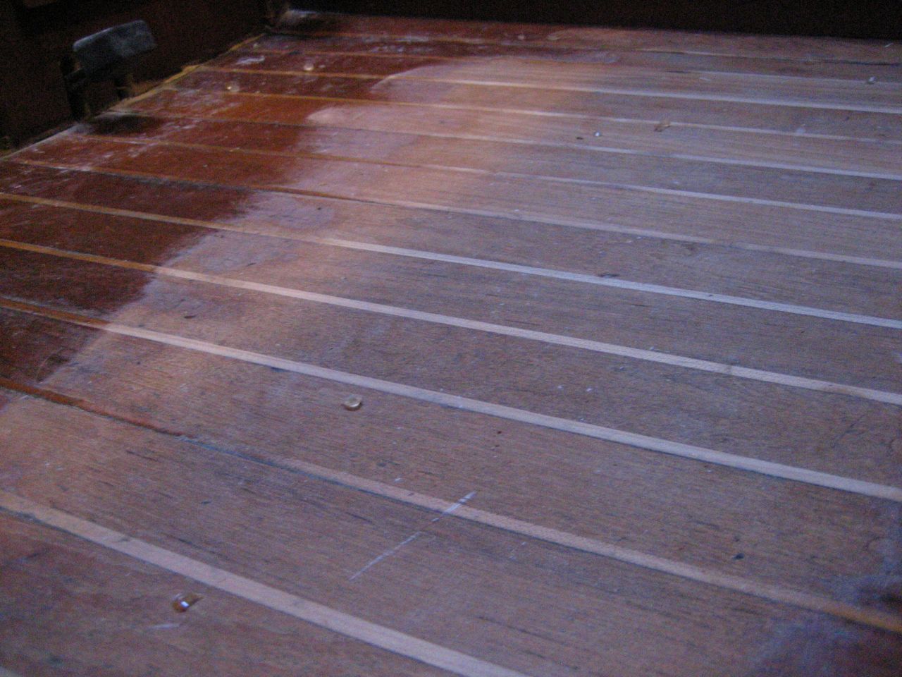
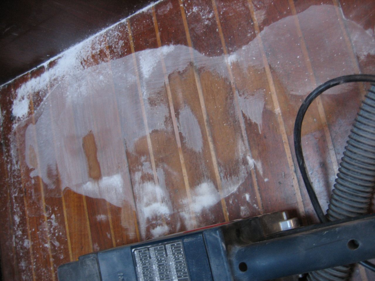
1) sand deck with 80grit
2) prepare spots that need fairing by digging out loose shards of gelcoat
3) vacuum up dust
4) wipe down spots that need fairing with acetone
5) mix up a batch of Quikfair and apply to all prepared digs, holes, scratches, etc
6) sand down quikfaired areas with 80 grit
7) if inadequately faired with only one round, repeat steps 3-6
8) vacuum all dust
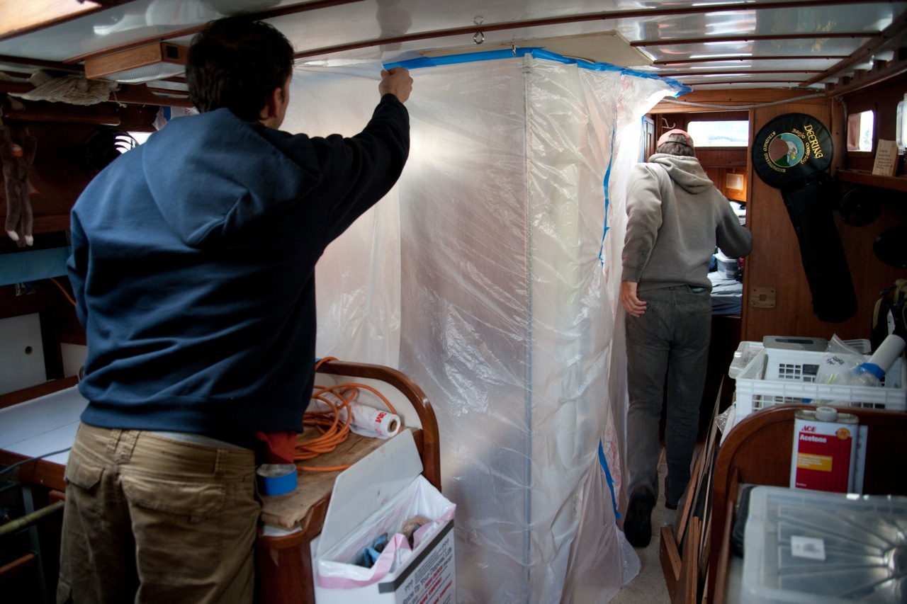
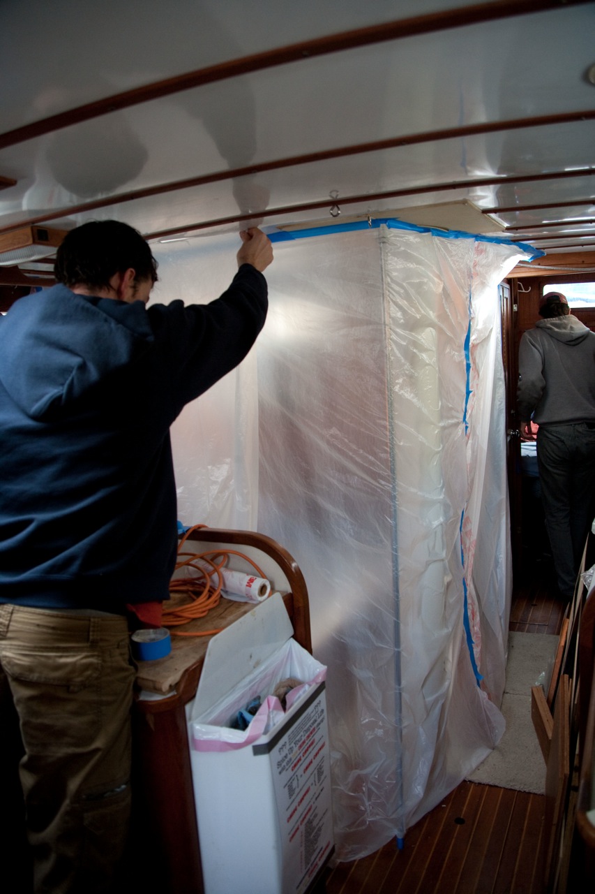
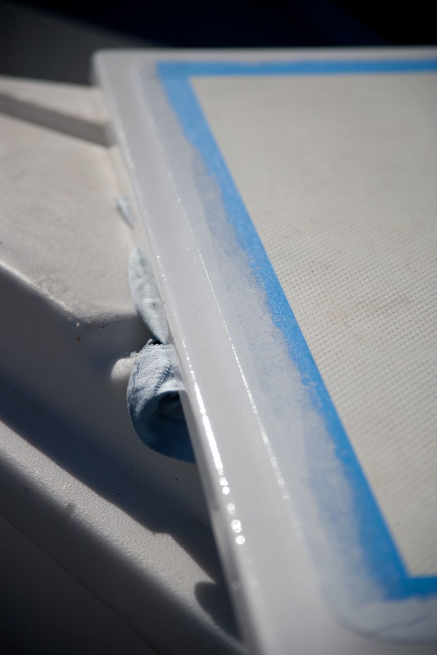
9) mask off
10) wipe down/clean the deck with the thinner (in this case Interlux 2333N)
11) paint coat 1 of two-part epoxy primer (I used Interlux Primekote)
12) lightly sand with 120grit
13) vacuum all dust
14) wipe down with 2333N
15) paint coat 2 of two-part epoxy primer
16) lightly sand with 120 grit
17) vacuum all dust
18) re-mask off for only LP areas
19) wipe down with 2333N
20) paint coat 1 of LP (I used Interlux Perfection)
21) lightly sand with 320 grit
22) vacuum all dust
23) wipe down with 2333N
24) paint coat 2 of LP
25) re-mask for only non-skid areas
26) wipe down with acetone
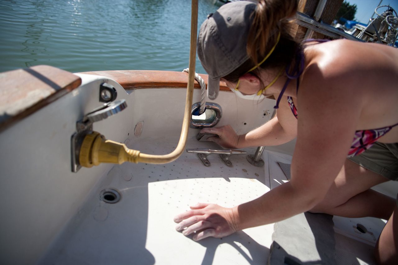
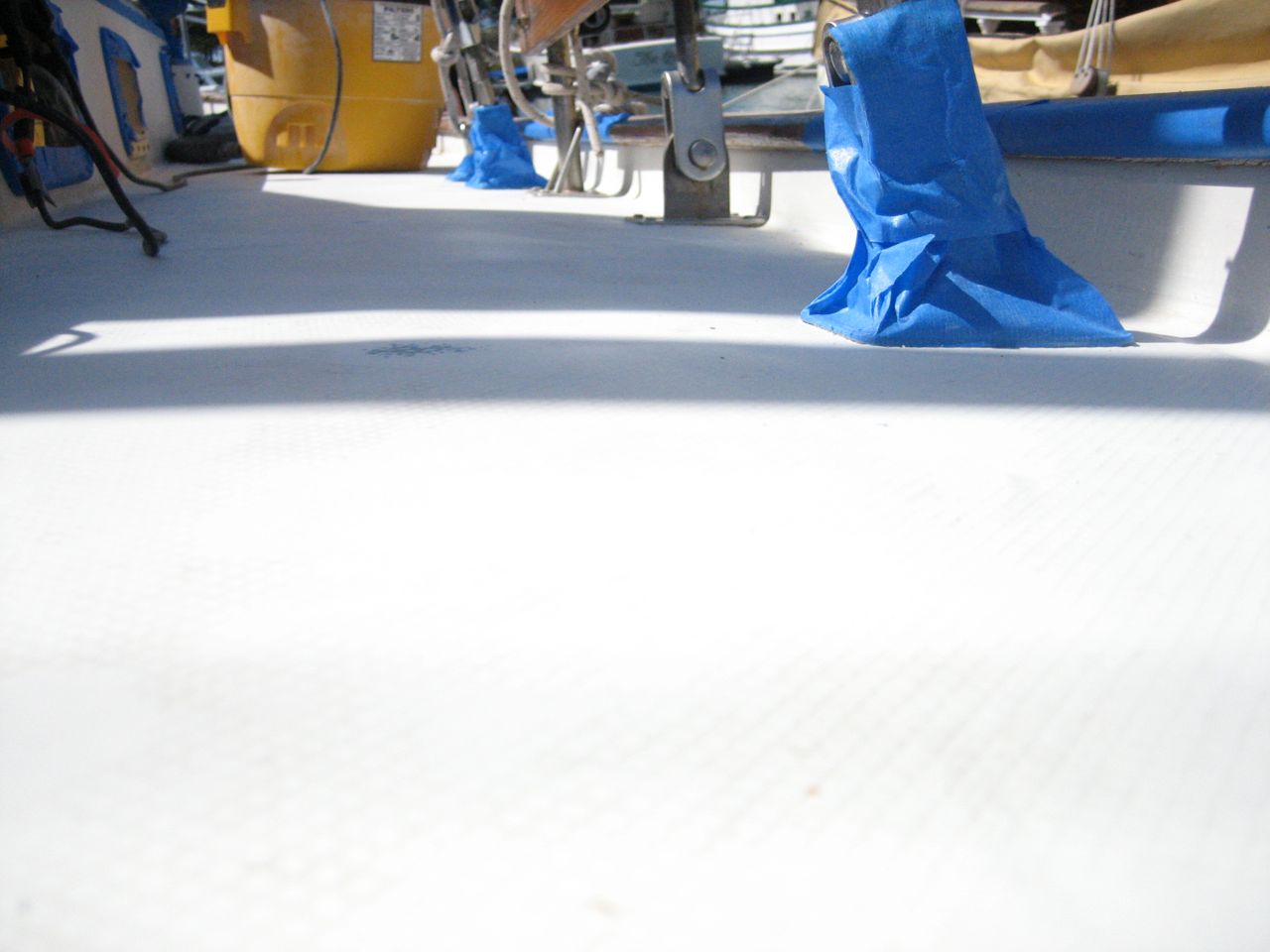
27) paint kiwi-grip (one coat only (hopefully!))
27) pull up tape and admire
28) repeat steps 1-27 for other sections of the deck
One thing I’ve learned from this whole affair is that all of the two-part stuff is way more of a pain in the ass than all of the one-part stuff. To start with, you can just open a can of the one-part stuff, mix it up, and start going. And then close up the can at the end of the day. With the two-part products, you need to open both cans, use little mixing cups or spoons or something to very accurately measure out perfect amounts of each, then use up the whole mixture usually within an hour or so (there’s always a time limit on the two-part stuff), and whatever extra you have is wasted, but usually you’ll end up being about a quarter cup short, but you sure as hell don’t want to mix up another cup full of the stuff because it costs almost as much as gold. Not to mention all of the two-part products are about 10 times more toxic and deadly than the one-part products–this includes the two-part epoxy bilge paint from sherwin-williams that gave me a headache for a day (I was stupid it was my fault, no respirator that time), the two-part epoxy bottom paint primer we used before painting the hull, the two-part epoxy primer paint (Primekote) I use on the deck, the two-part polyurethane Interlux Perfection, and even the regular old West System two-part epoxy (redundant since all epoxy is two-part). Contrast this with the kiwi-grip, which is an acrylic water-based paint: I open the can, slap it on the deck with a brush, roll it out with the roller they provide, then put the lid back on and rinse everything out quickly and easily with water.
True, the LP will last a long time. But on the other hand, wherever the non-skid starts to wear off, I can just grab the can and goop some more on in a matter of minutes (if I’m not too lazy to just ignore it for years that is). Both approaches have their appeal. After throwing away hundreds of small paper cups and whatnot in the course of mixing up these two-part poisons, I have to admit the Kiwi-Grip’s ease of application was pretty refreshing (though I’ll be singing a different tune if it only lasts a few months before it starts to fall off).
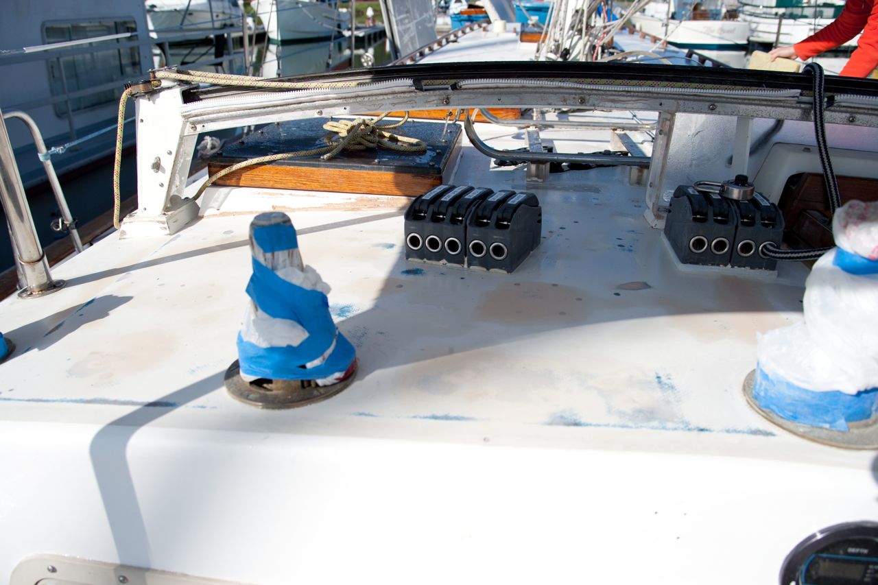
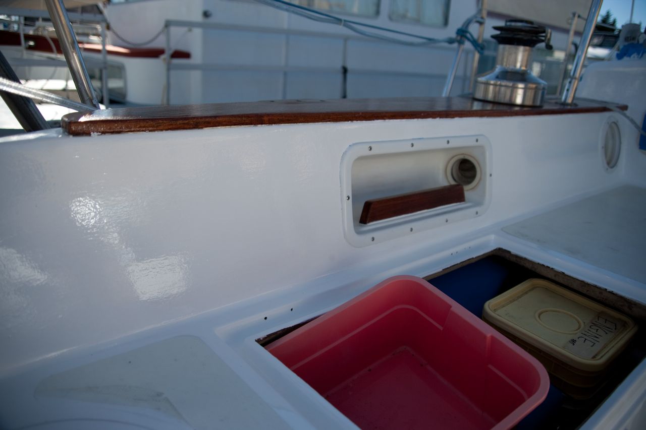
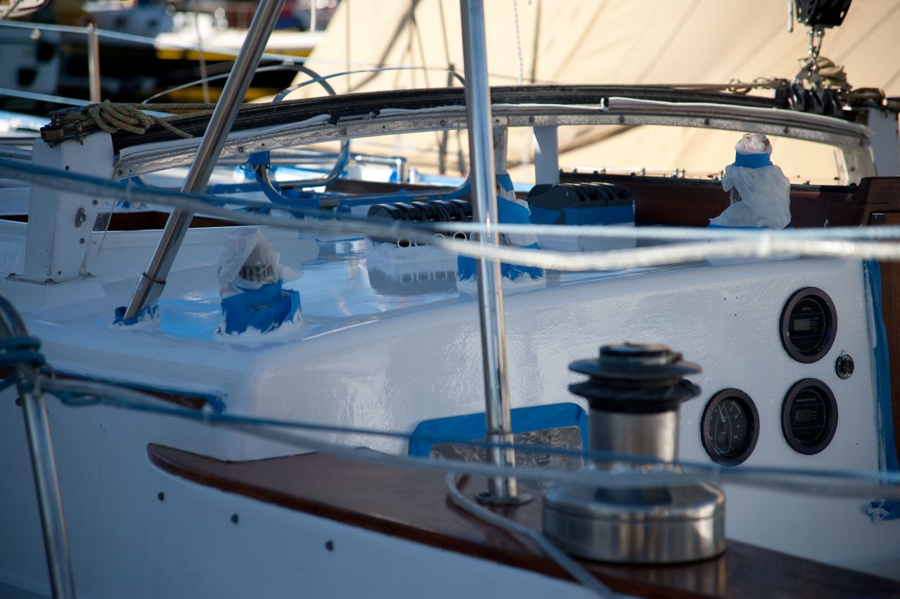
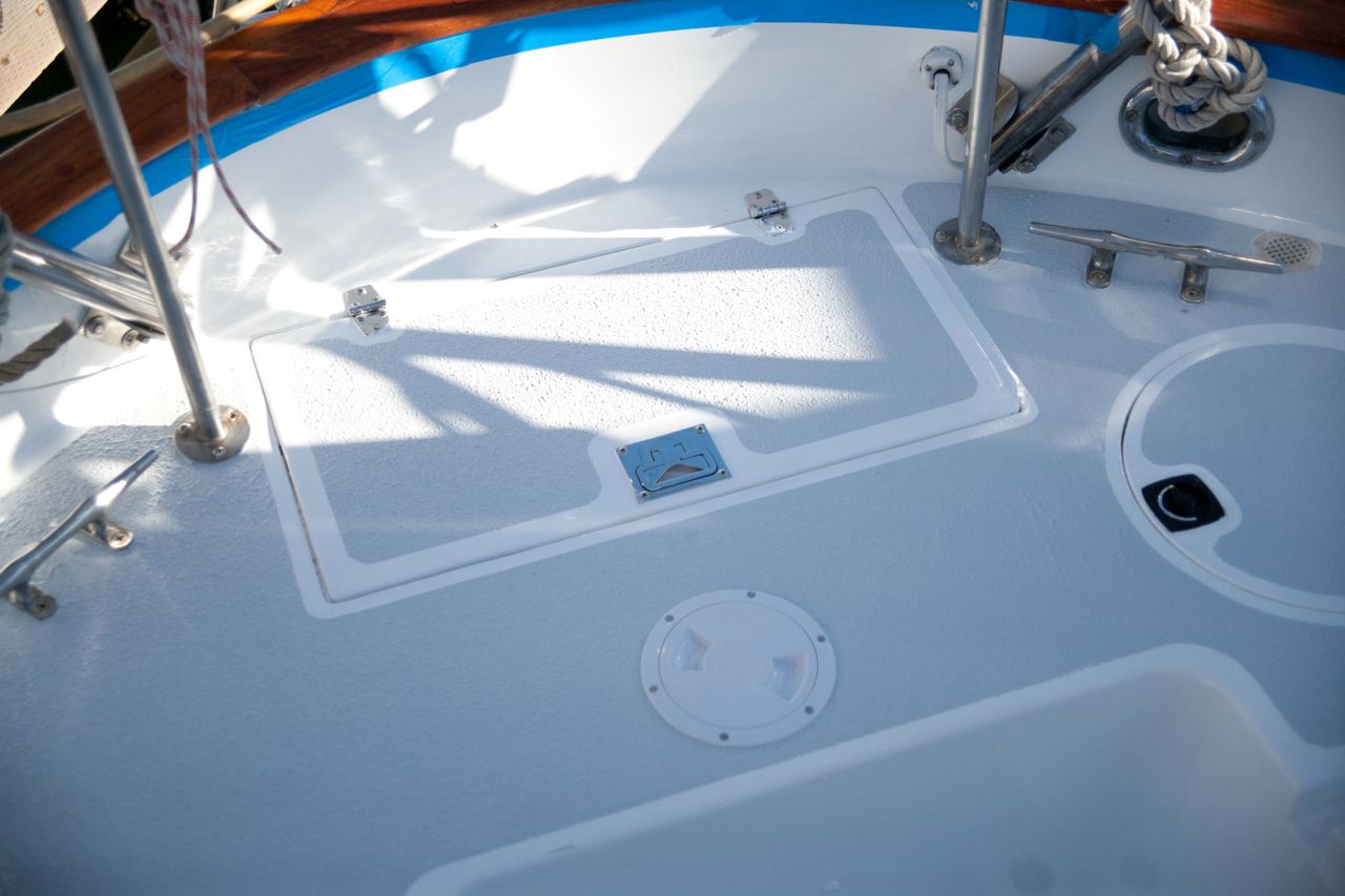
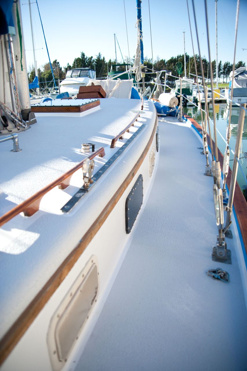
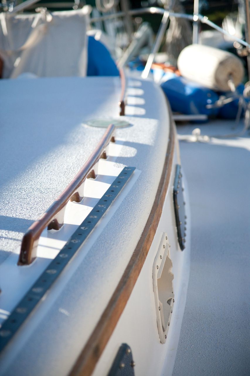
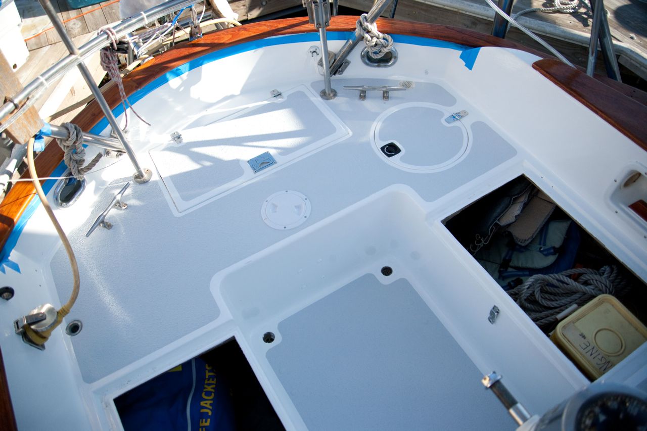
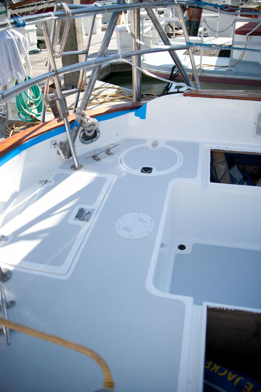
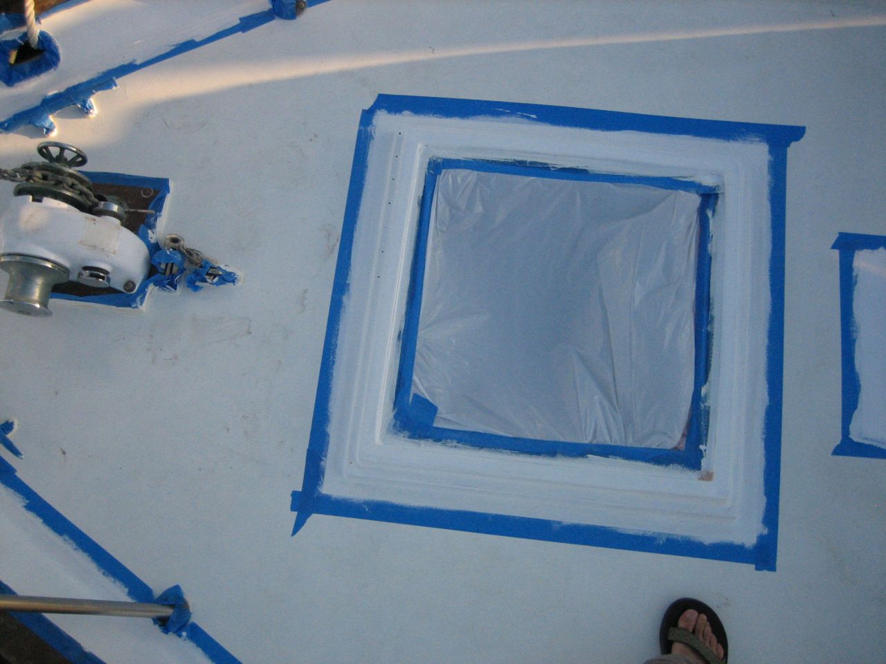
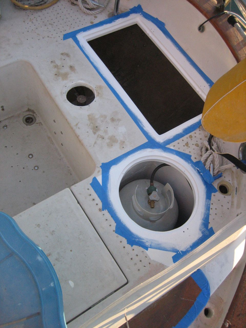
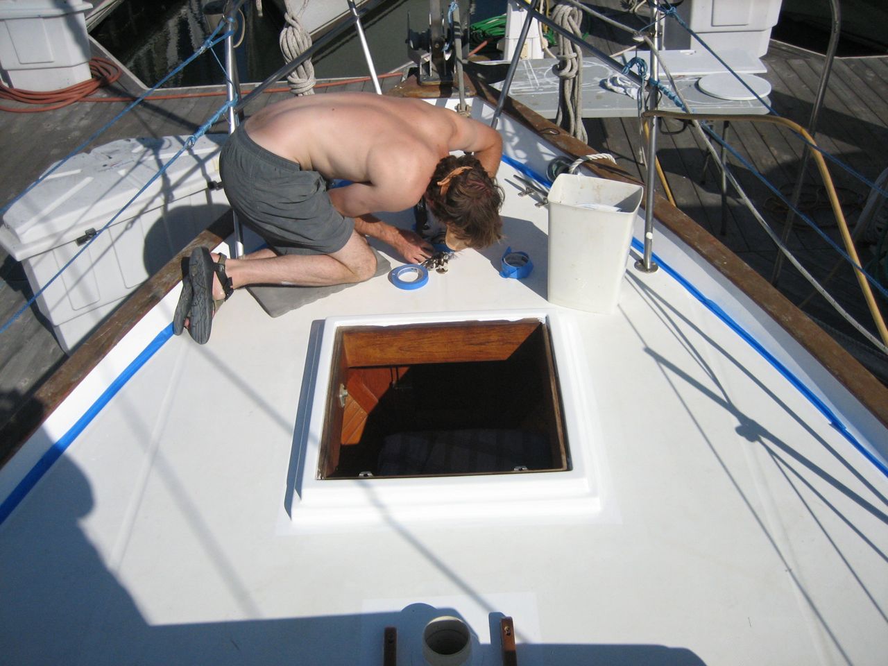
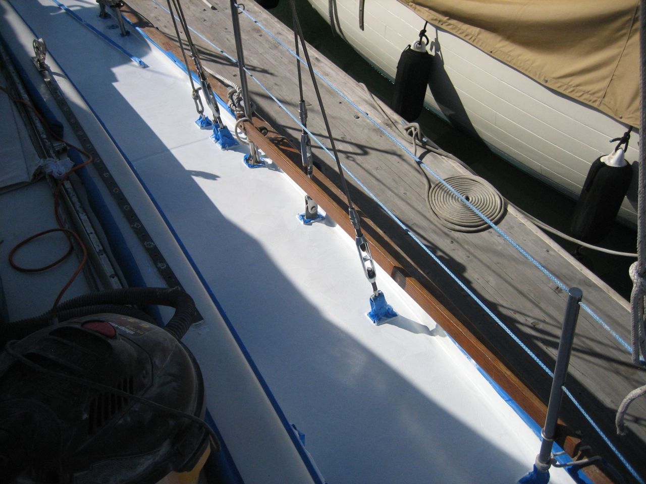
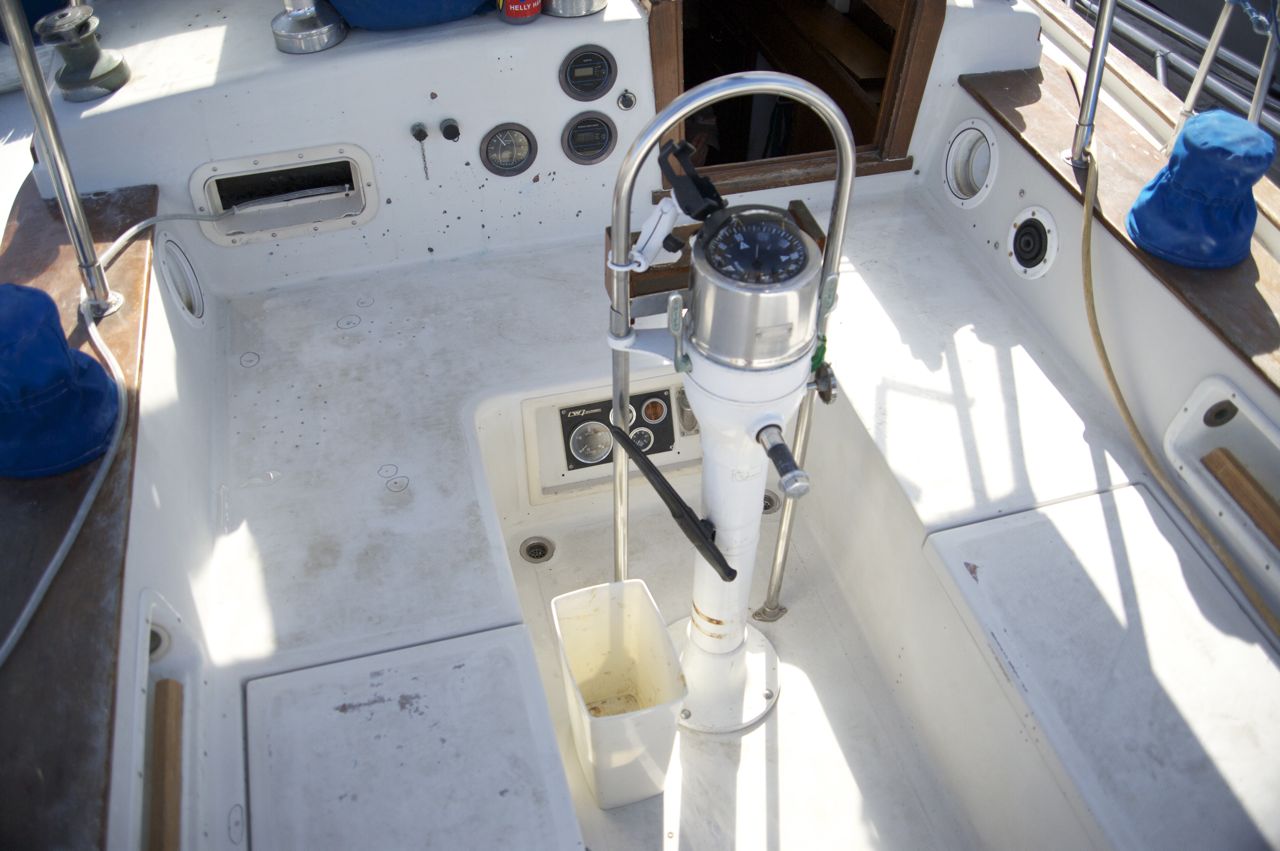
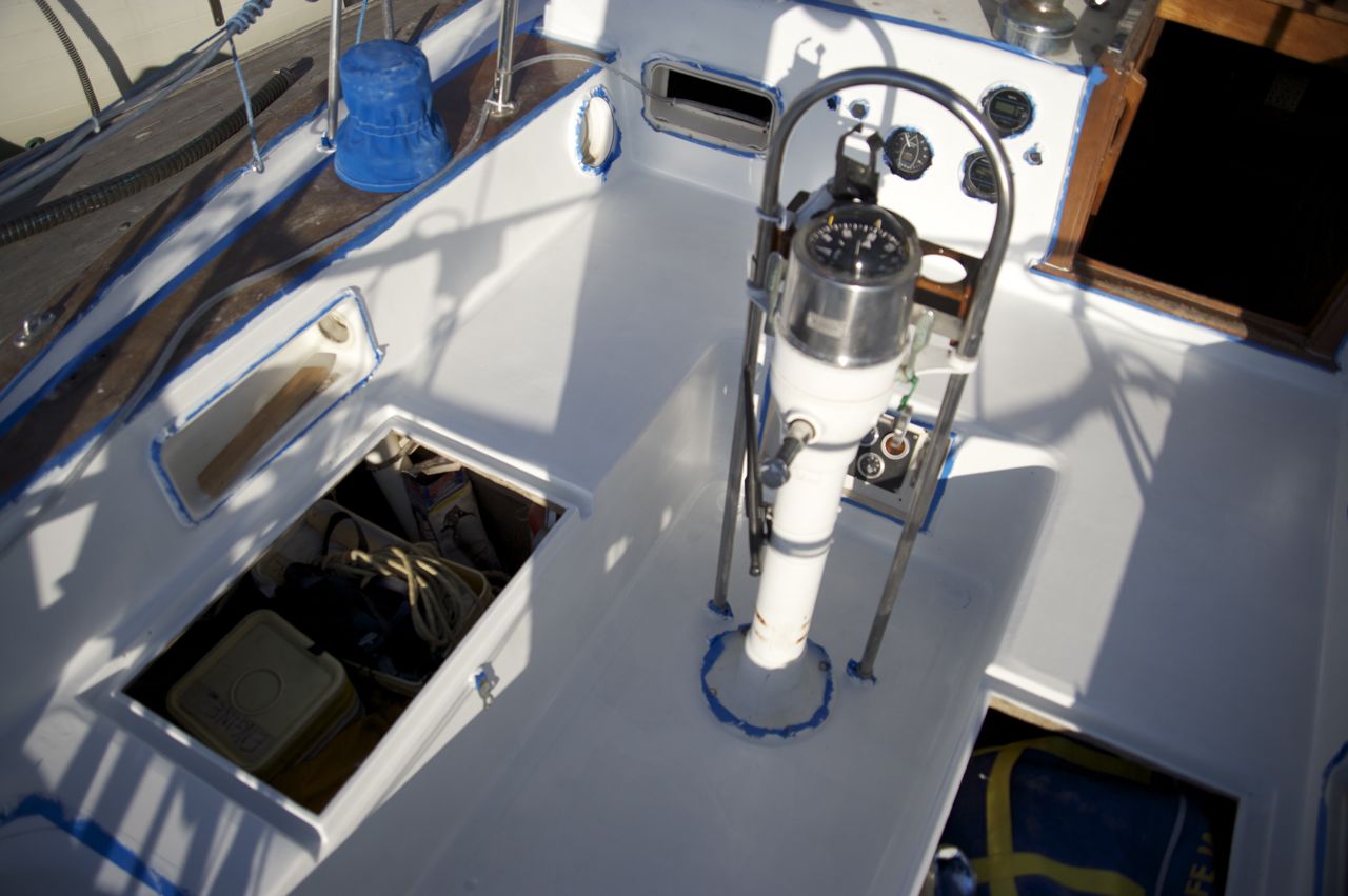
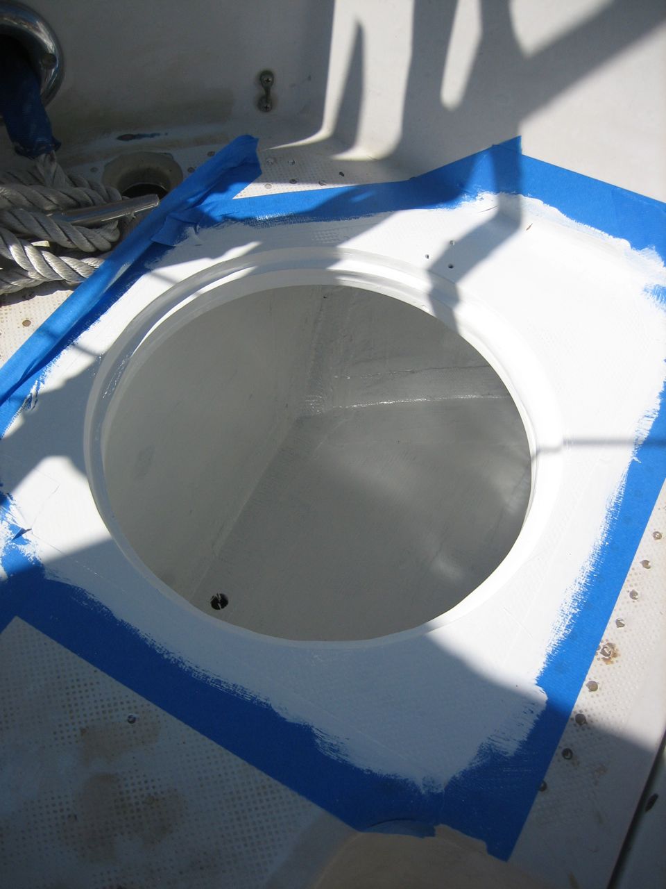
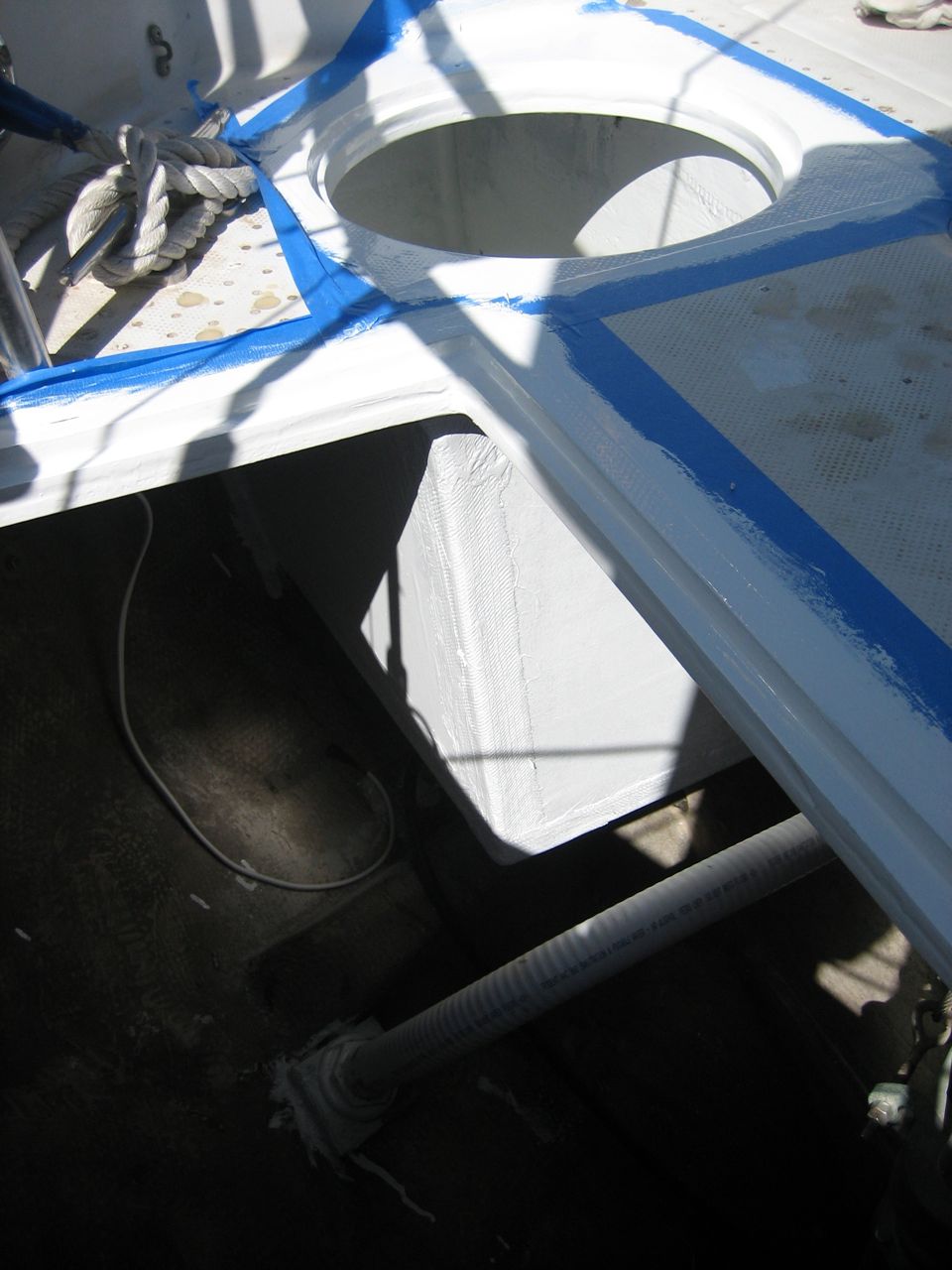
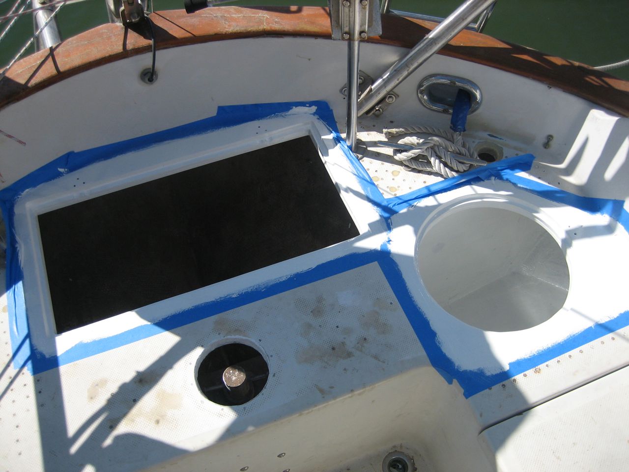
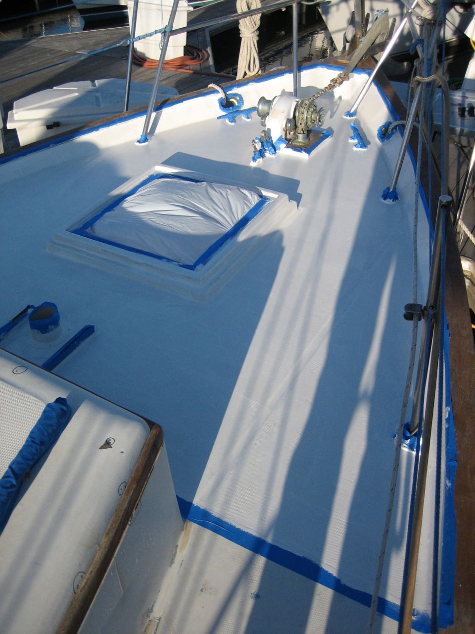
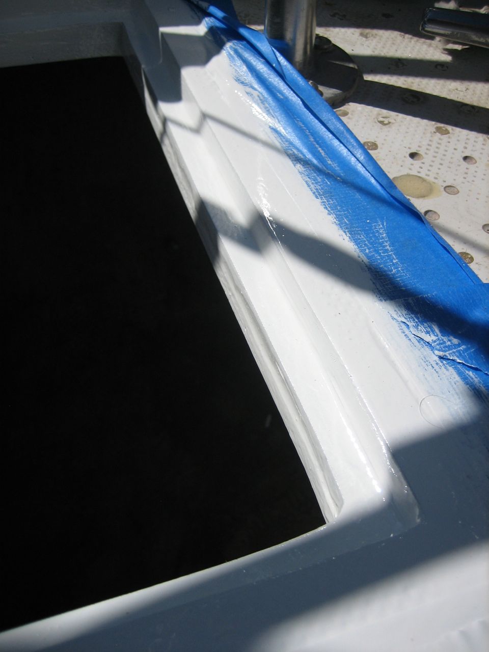
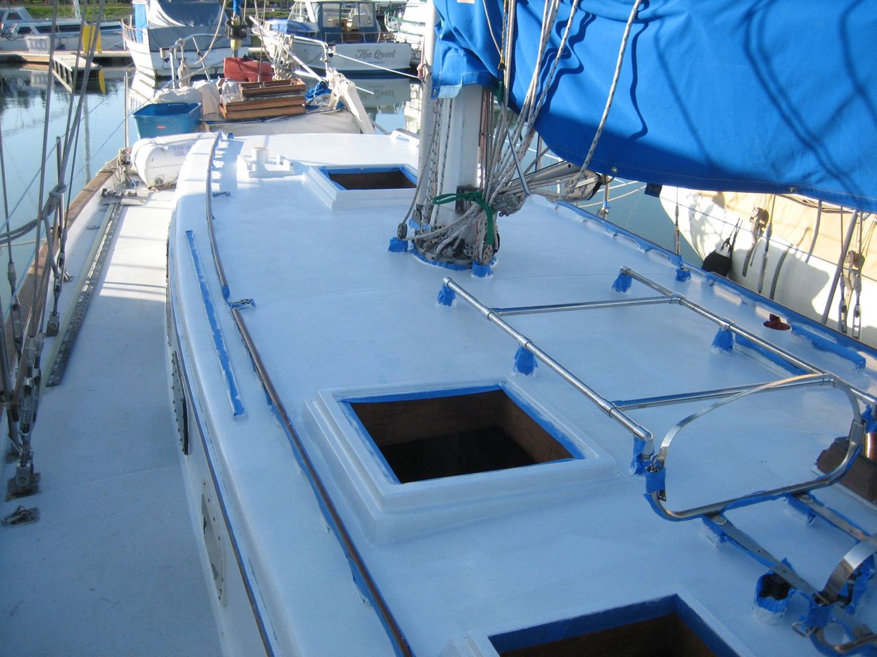
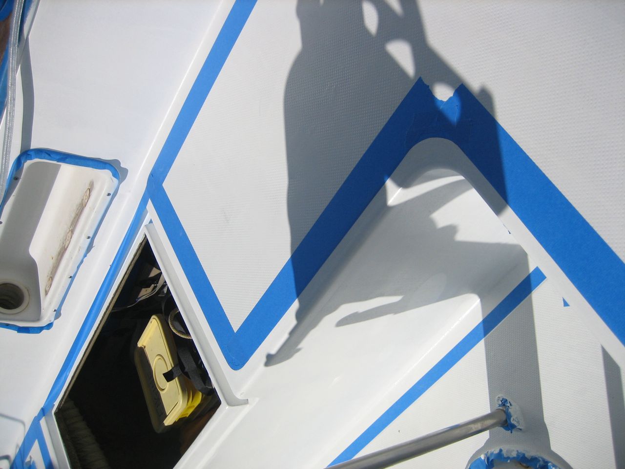
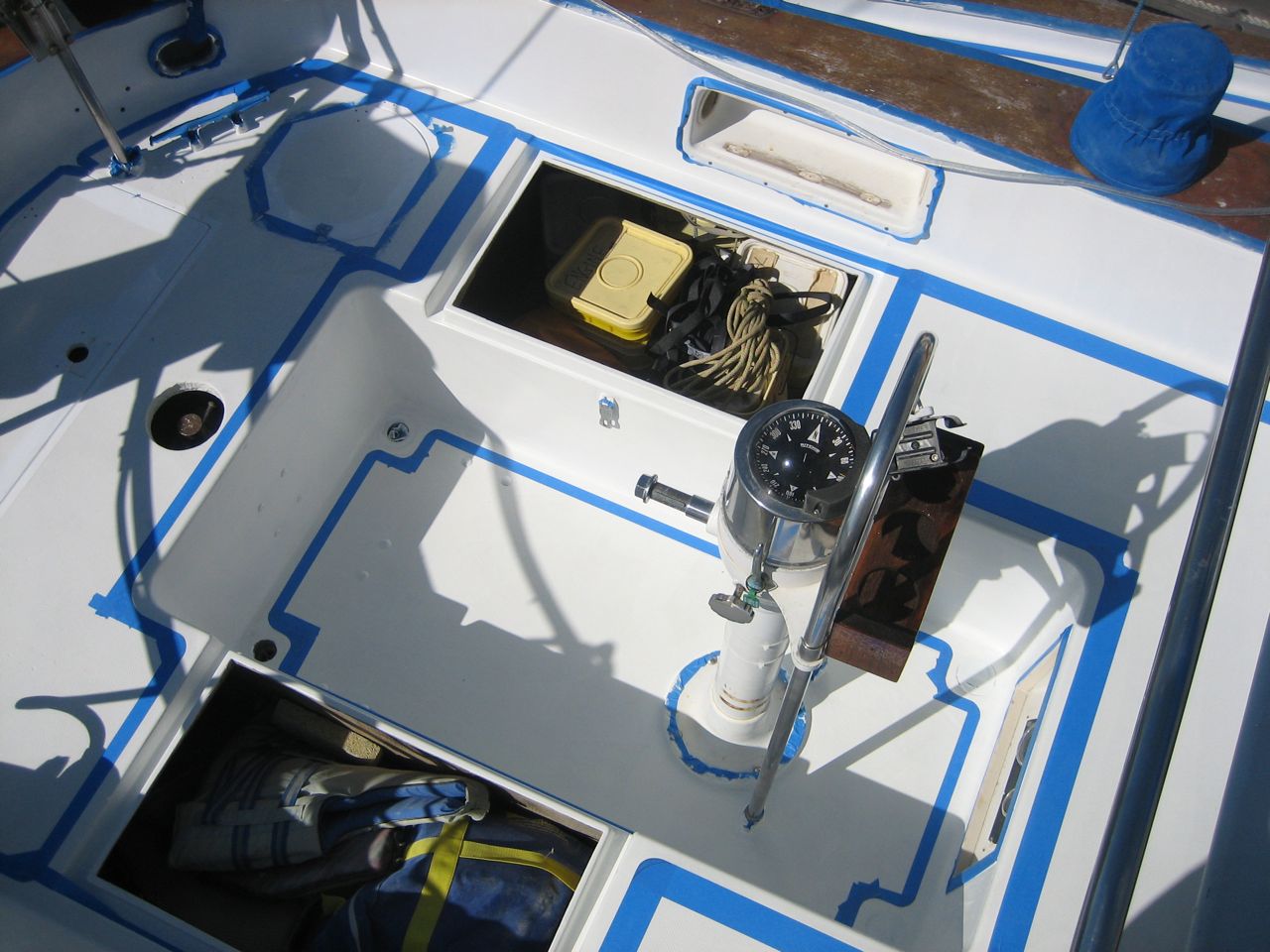
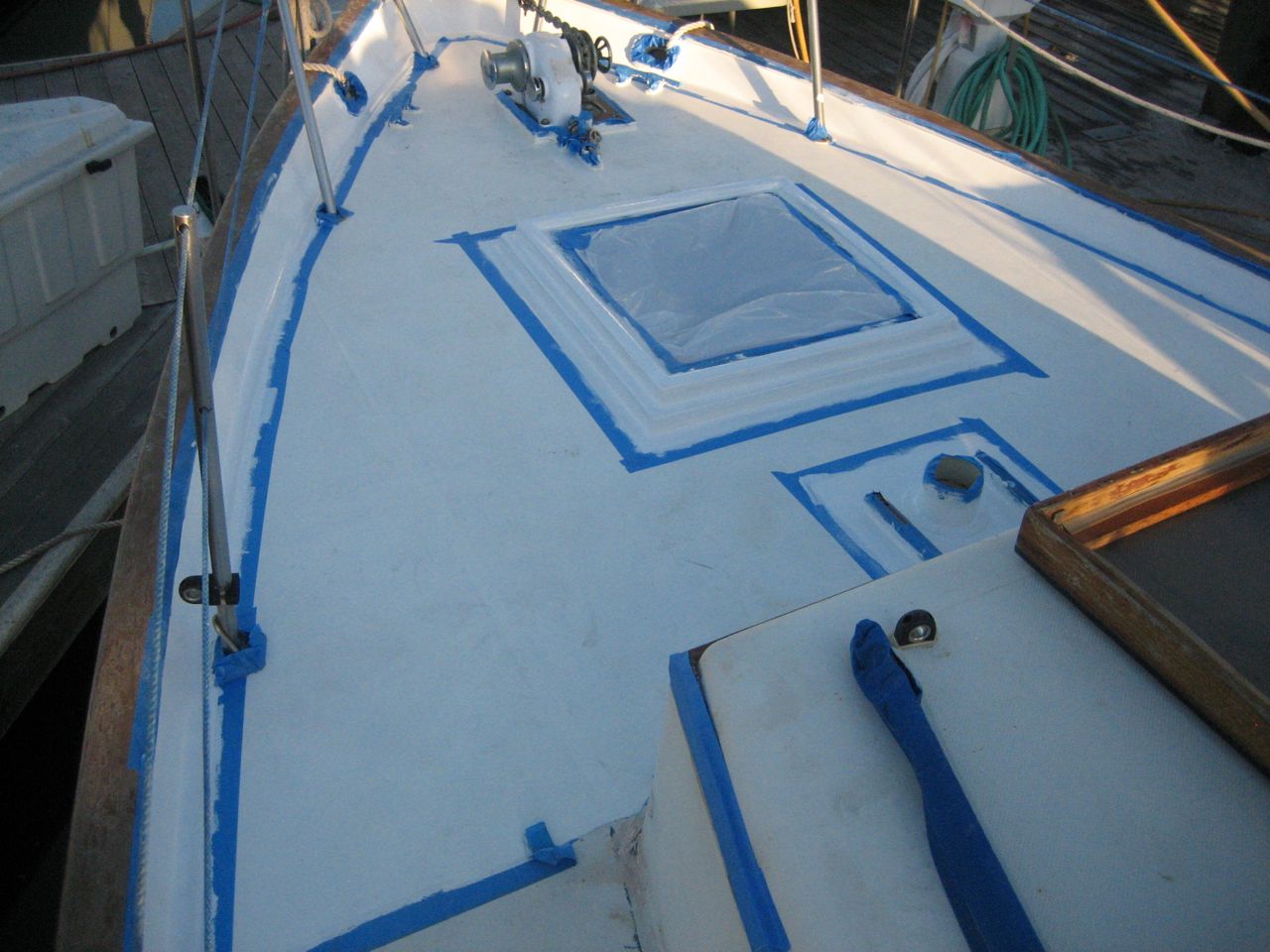
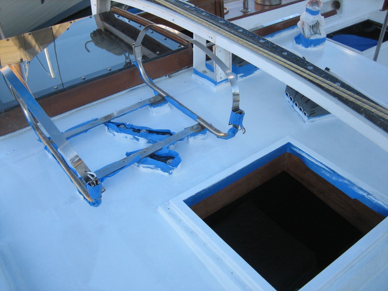
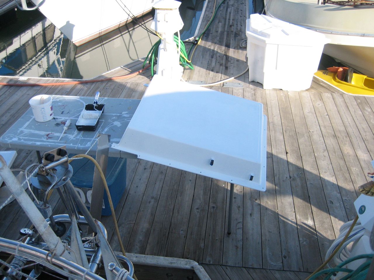
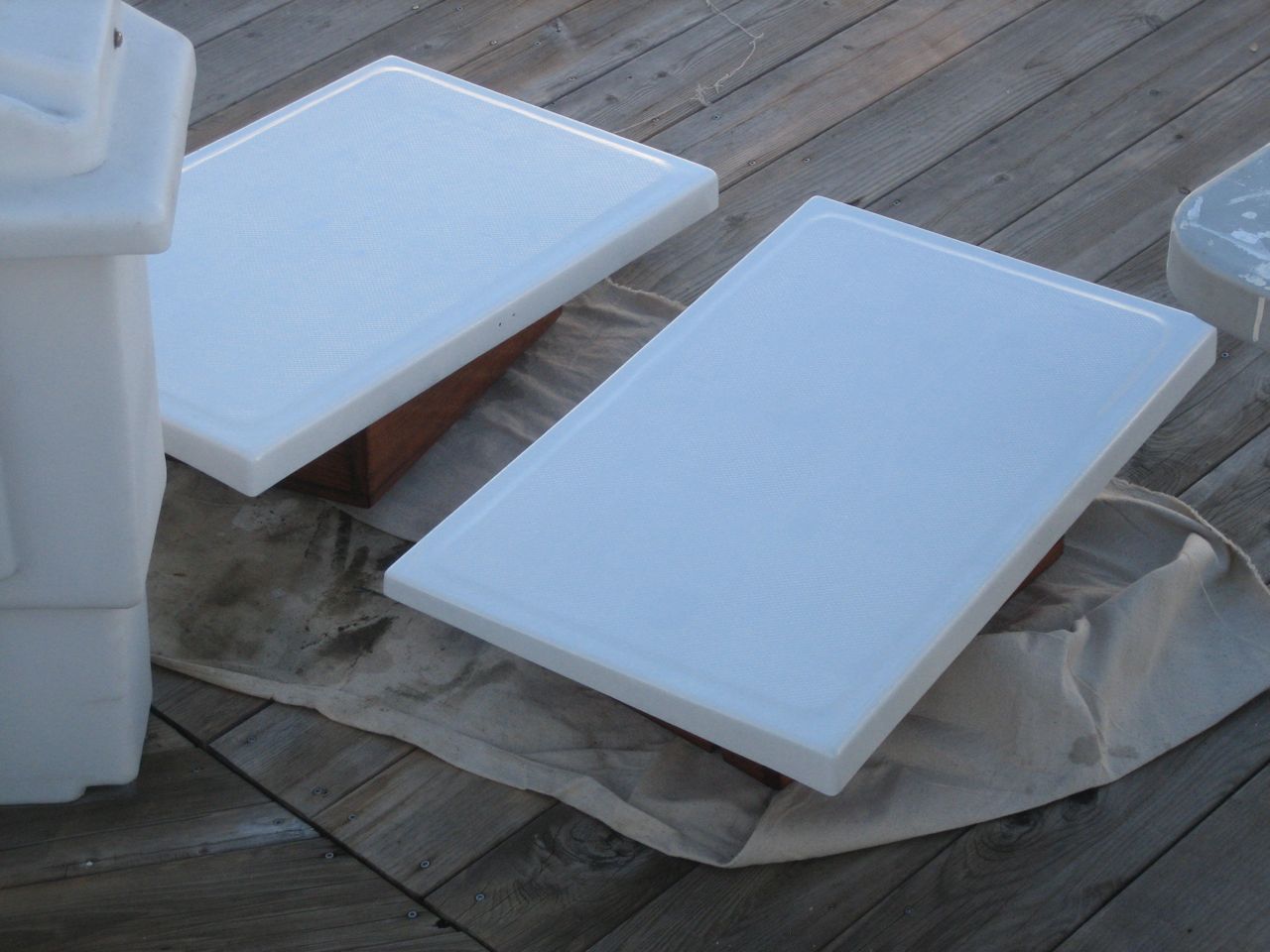
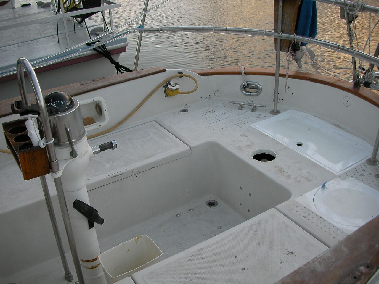
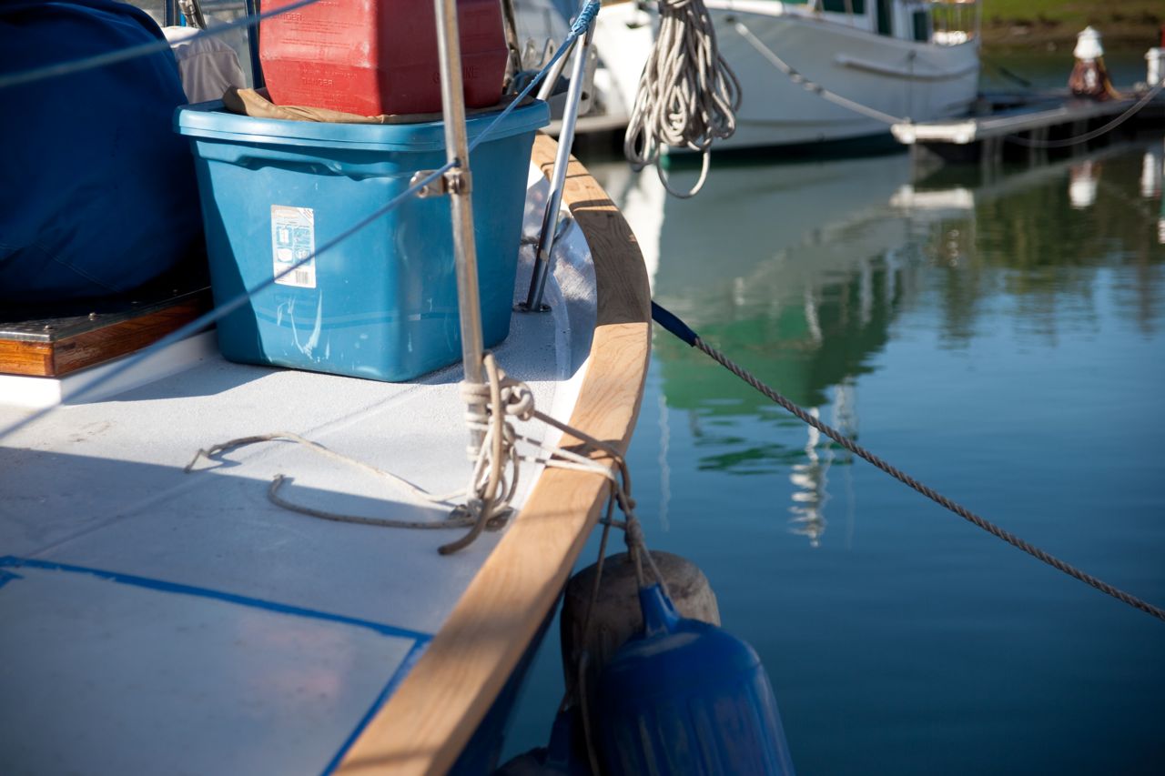
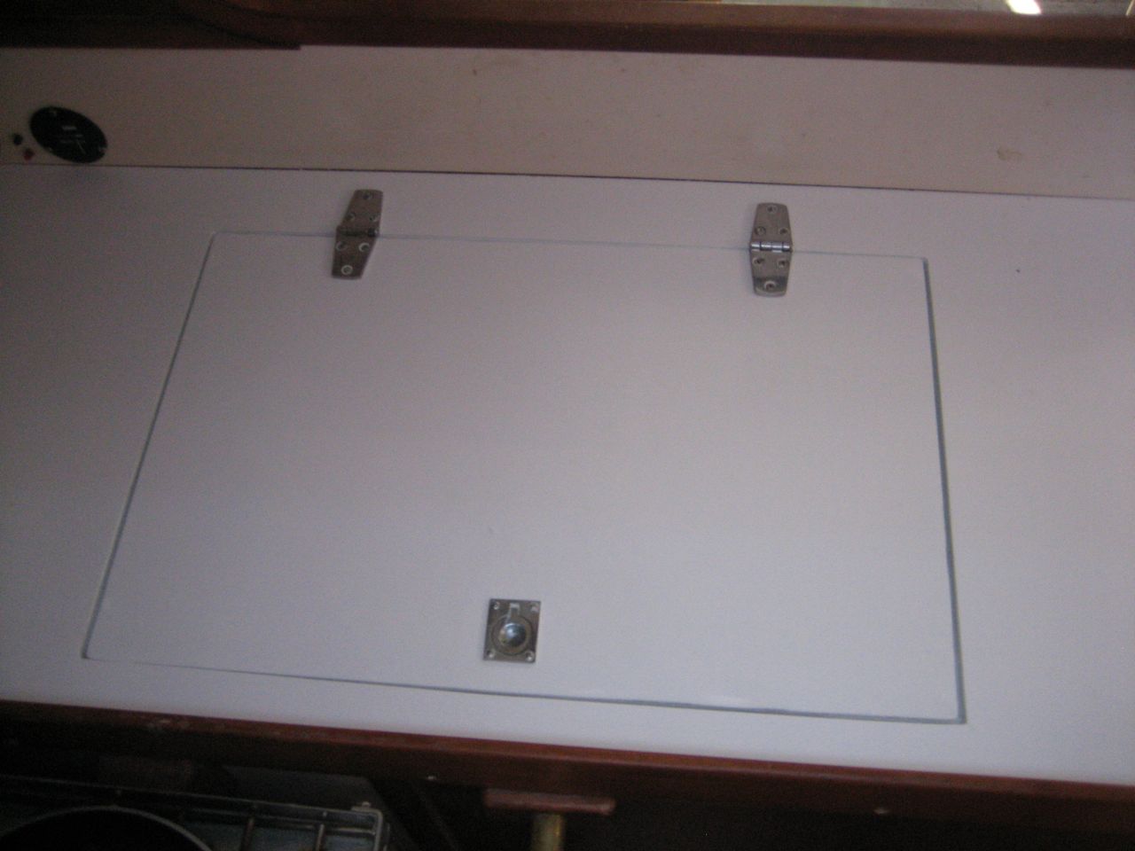
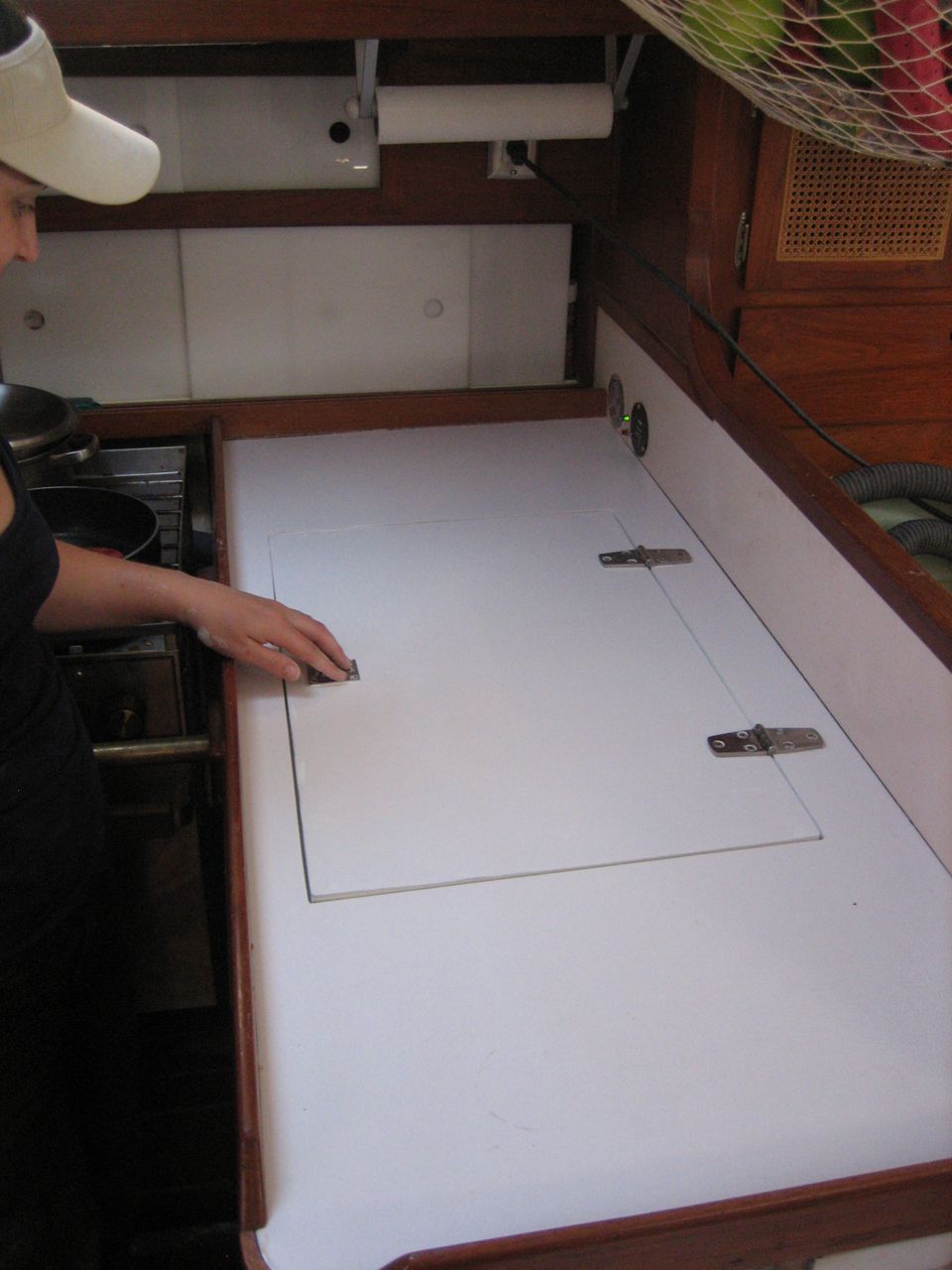
The pictures in the galley are in chronological order of how the boat was painted. I did not sand the whole boat, then mask the whole boat, etc. I did it in pieces. First I did the rims and lids of the propane locker and lazarette with the primer and LP, then I did the foredeck with primer, then masked for the LP, then remasked for the non-skid on the foredeck. Then I ran out of kiwi-grip on the foredeck and ordered more.
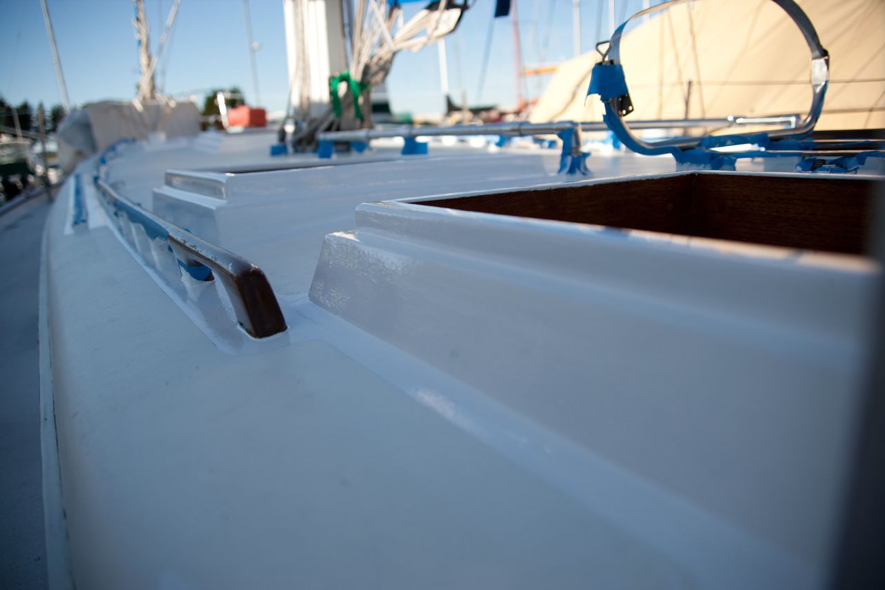
I learned, from doing the foredeck to completion first as a proof-of-concept, that you don’t want to put kiwi-grip down over the LP (I had inexactly masked before painting the LP, assuming that the edge of the LP didn’t matter once I put kiwi-grip over it). I knew better but forgot. Two reasons not to let the kiwi-grip end up over top of any LP: 1) it won’t stick well to the LP 2) the LP will show through the kiwi-grip much more, being glossy bright white and whatnot. So after that I masked perfectly for the LP, then masked perfectly right next to it for the kiwi-grip.
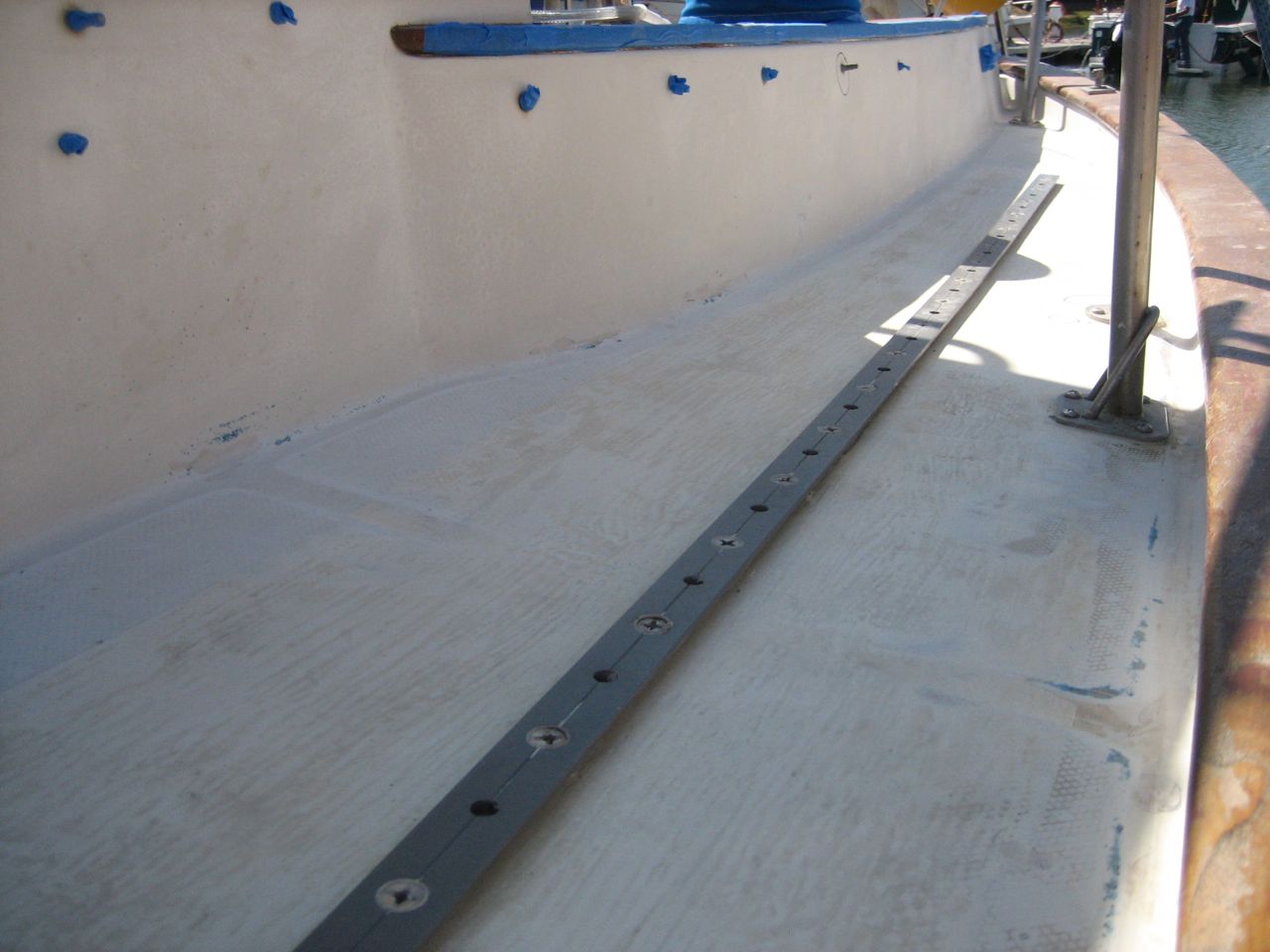
After the foredeck, I did the port side deck and cockpit, more or less together. I did it in pieces because it was just too overwhelming to try to do each stage over the entire boat all at once (actually, I did it in pieces because Karen convinced me to, and then I saw the wisdom of her reasoning).