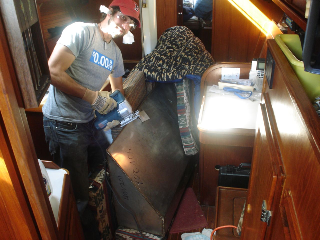
Over the past month Jonny has completely dismantled, cleaned, and regreased all of the winches except two–the last two need to be removed from the cockpit coaming for servicing. We still need to figure out what to do about the finish on the drum of a few of them; the chrome is half off and the resulting rough surface is eating up our halyards on the cabintop.
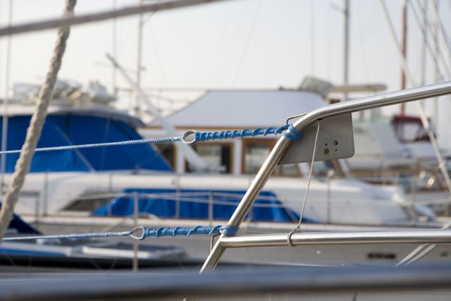
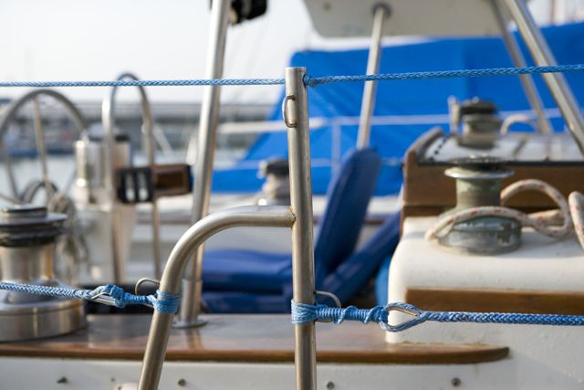
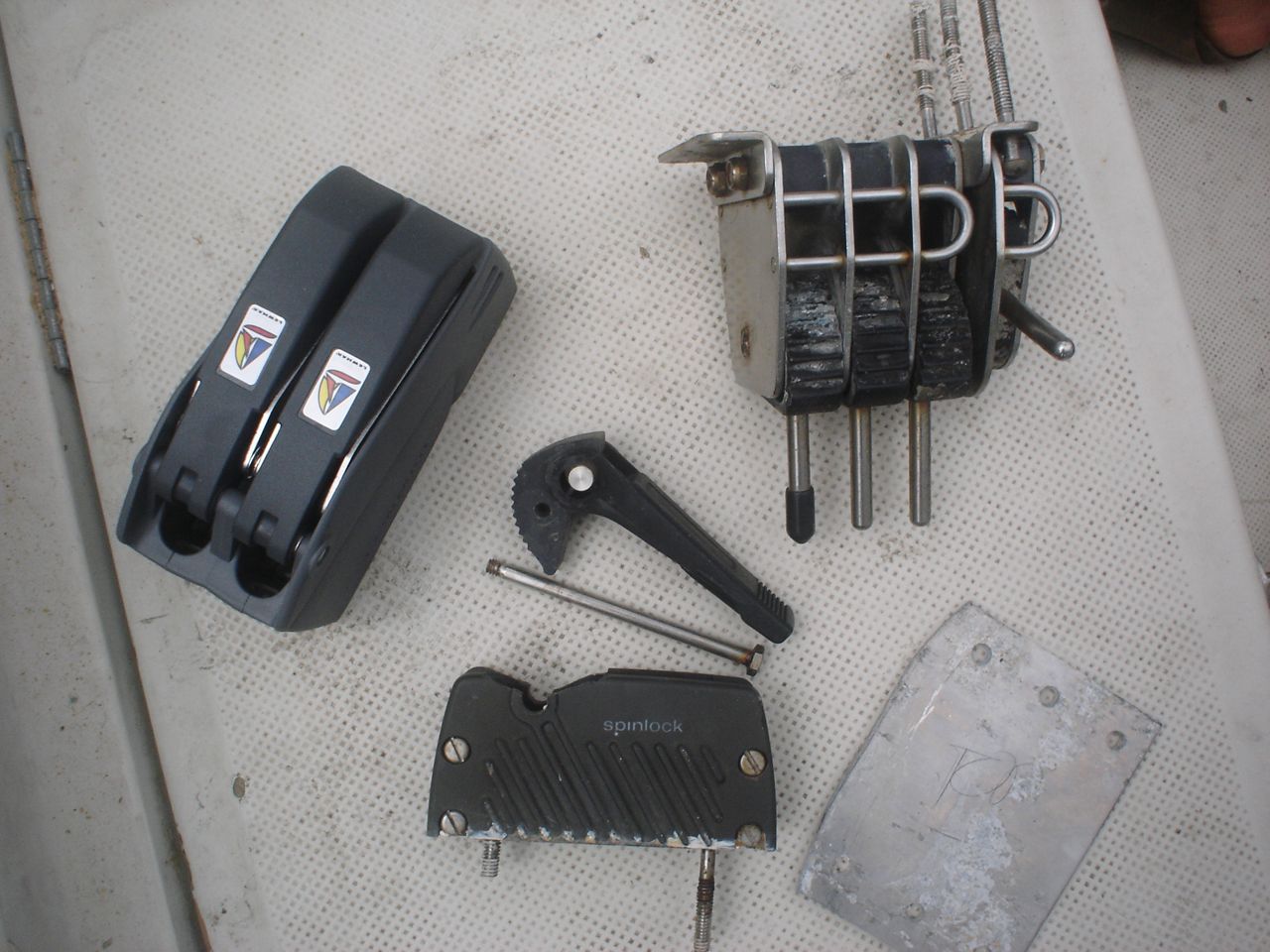
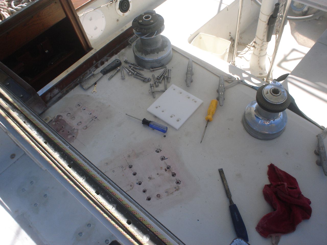
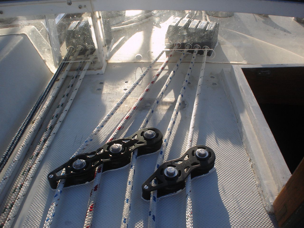
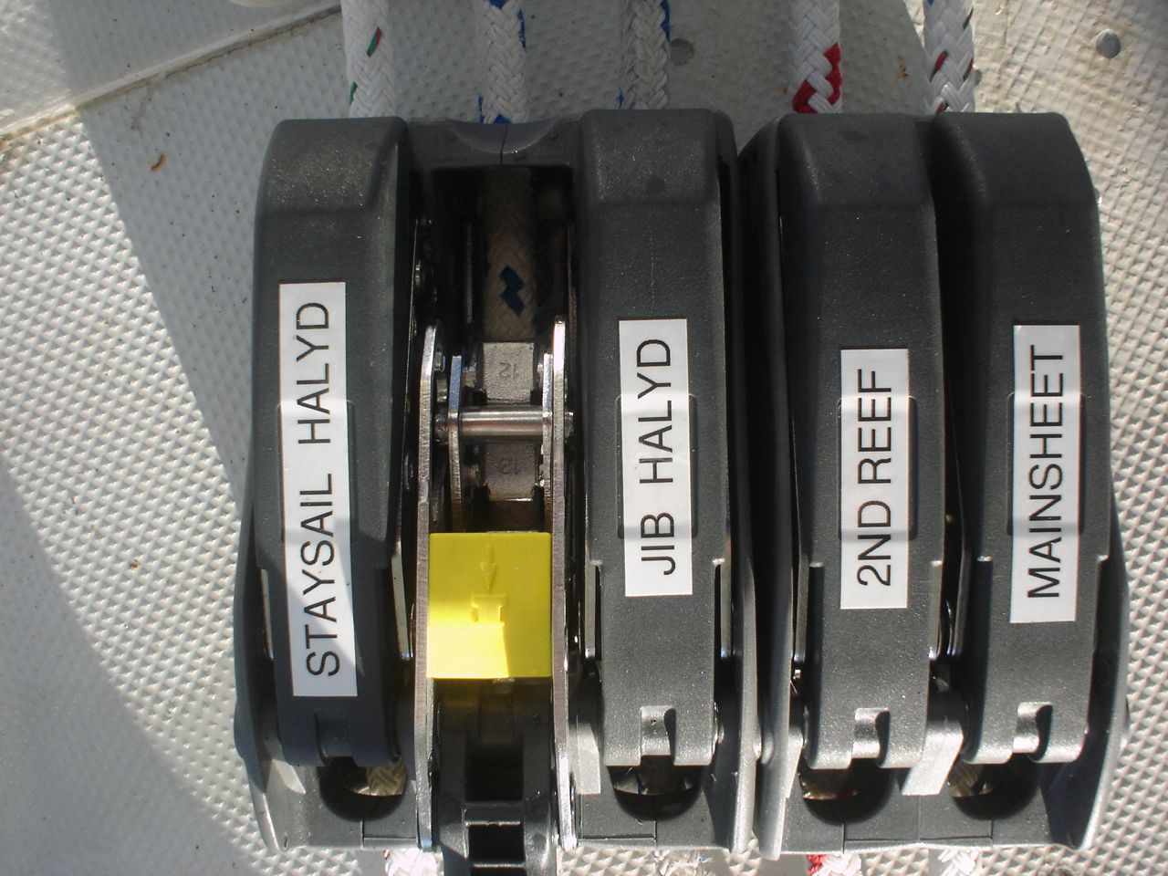
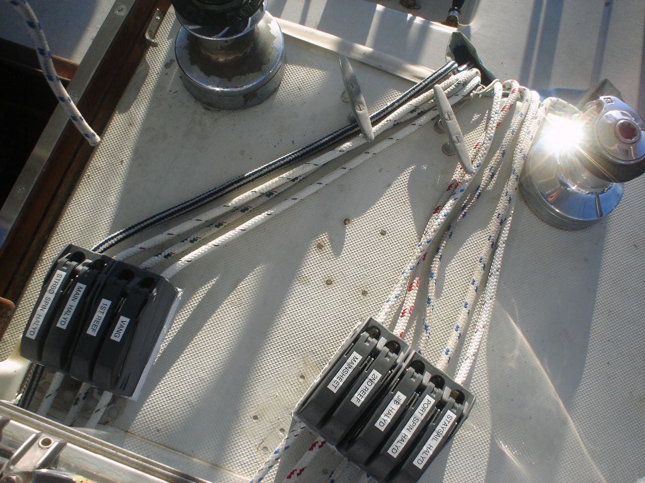
The old system: original jammer-style rope clutches, a mess of deck fairleads that no longer turned, lines crossed on the deck. The jammer-style clutches are frustrating because they can’t be released under load, which means that to drop a halyard for example you have to wrap it around the winch put the handle in and crank an inch just to be able to release the clutch. We tore out all the old deck fairleads and rope clutches and installed all new. We drilled and cored all the holes at the same time (old and new) and filled them with epoxy plugs. We cut large plates from our sheet of 316 stainless for backing blocks, and laboriously drilled all the necessary holes. The one bank of clutches needed to be elevated slightly off the deck for a fair lead; we used a piece of our UHMW (ultra high molecular weight) plastic to do the job. Everything was bedded with lifecaulk. In short, it was all done BTB (by the book). The new system is a dream–the boat is far easy and more pleasant to sail, largely because the friction is a fraction of what it was. It was worth every penny of the ~$1500 we spent on clutches and fairleads. I have to rank this as the most satisfying modification to our boat so far.
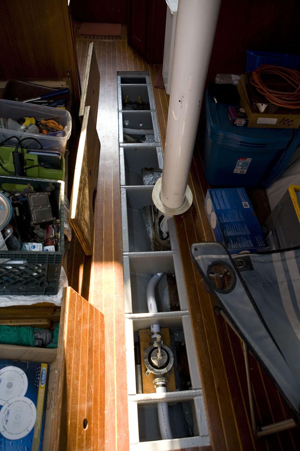
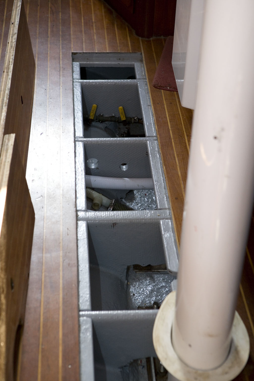
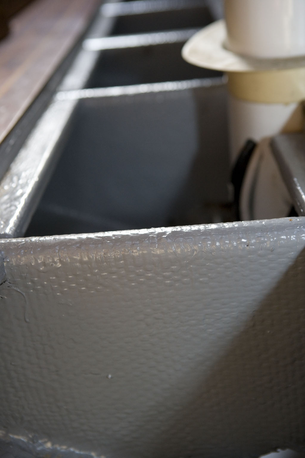
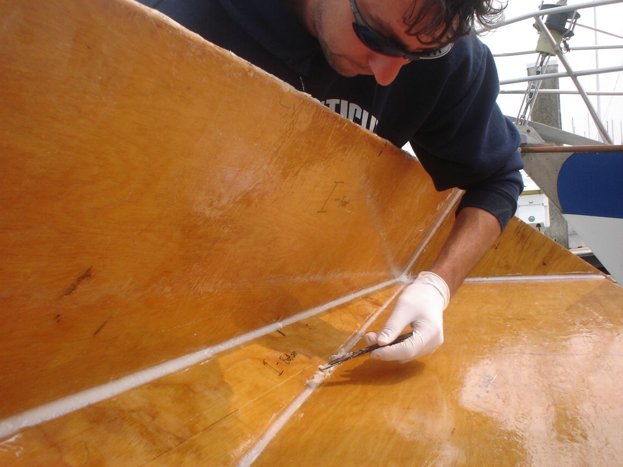
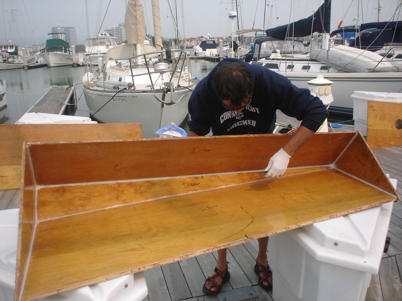
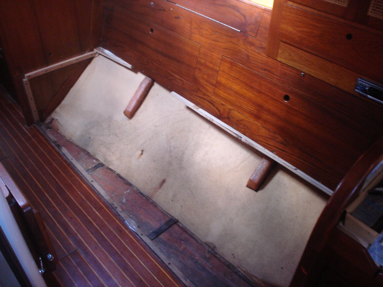
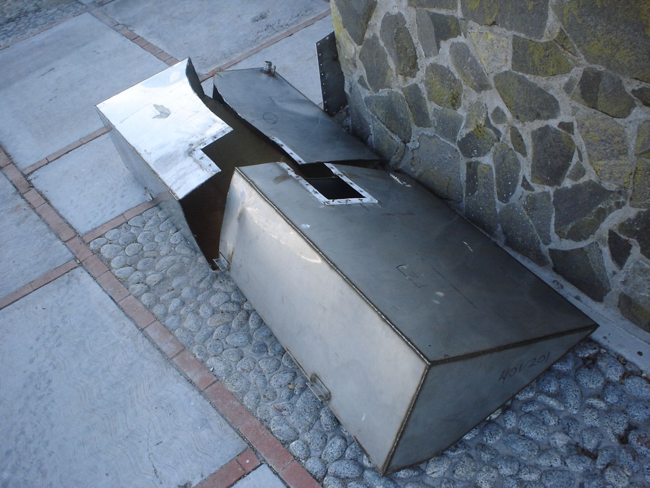
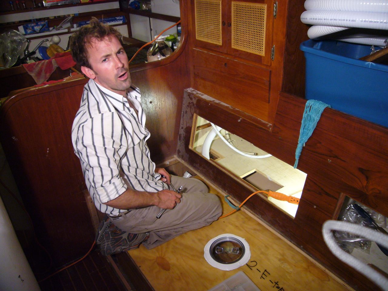
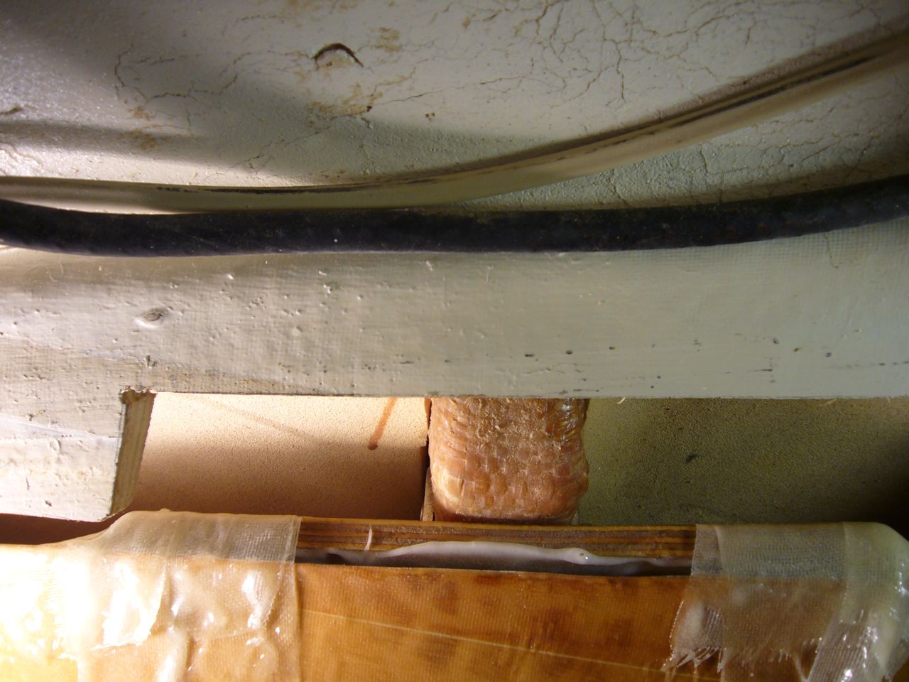
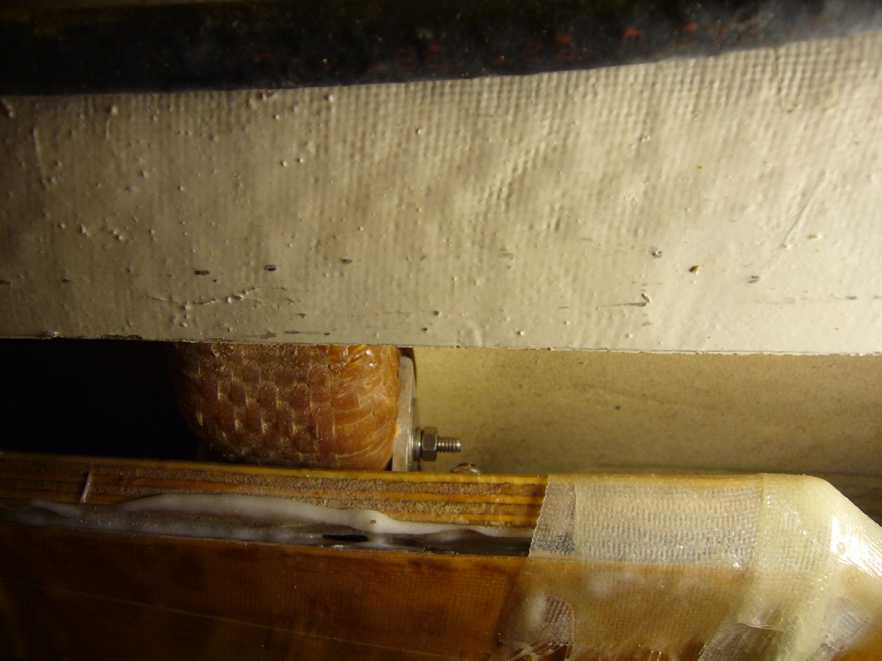
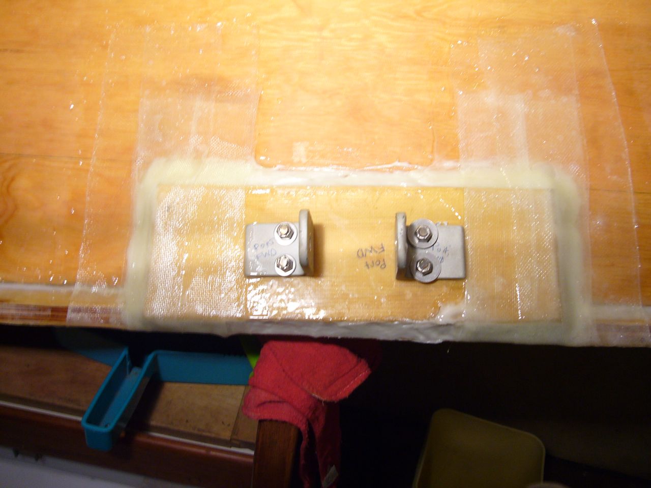
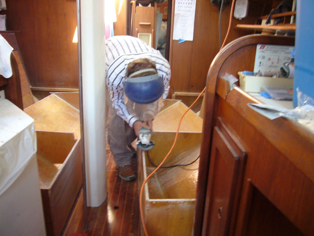
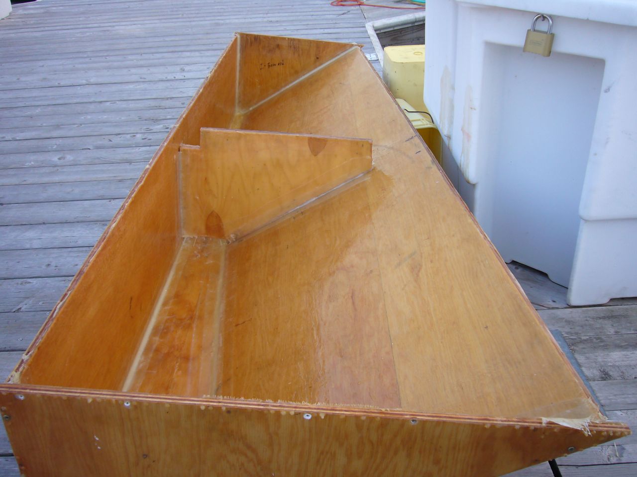
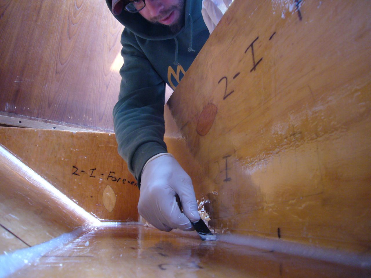
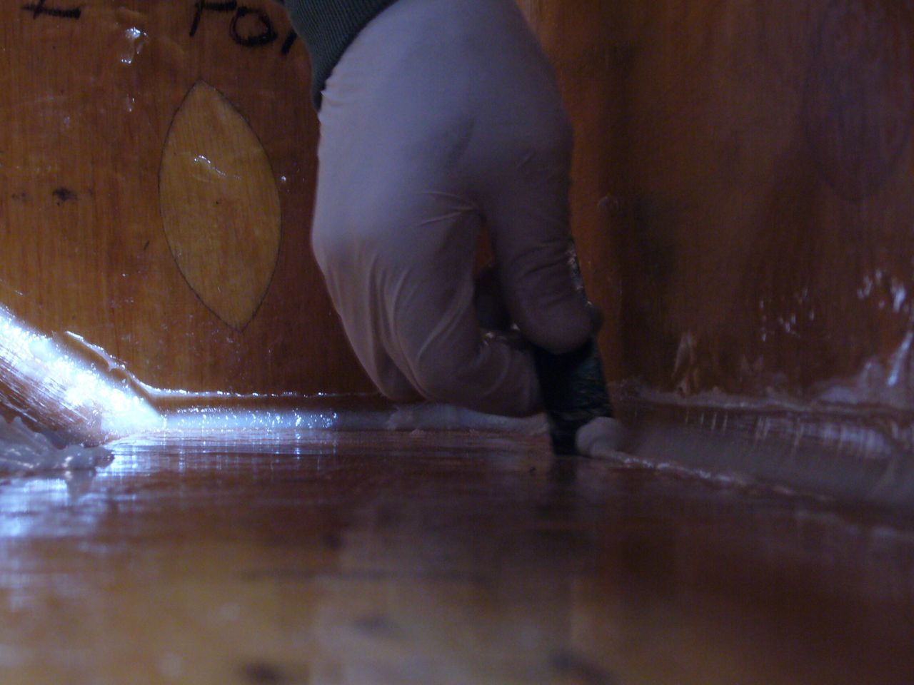
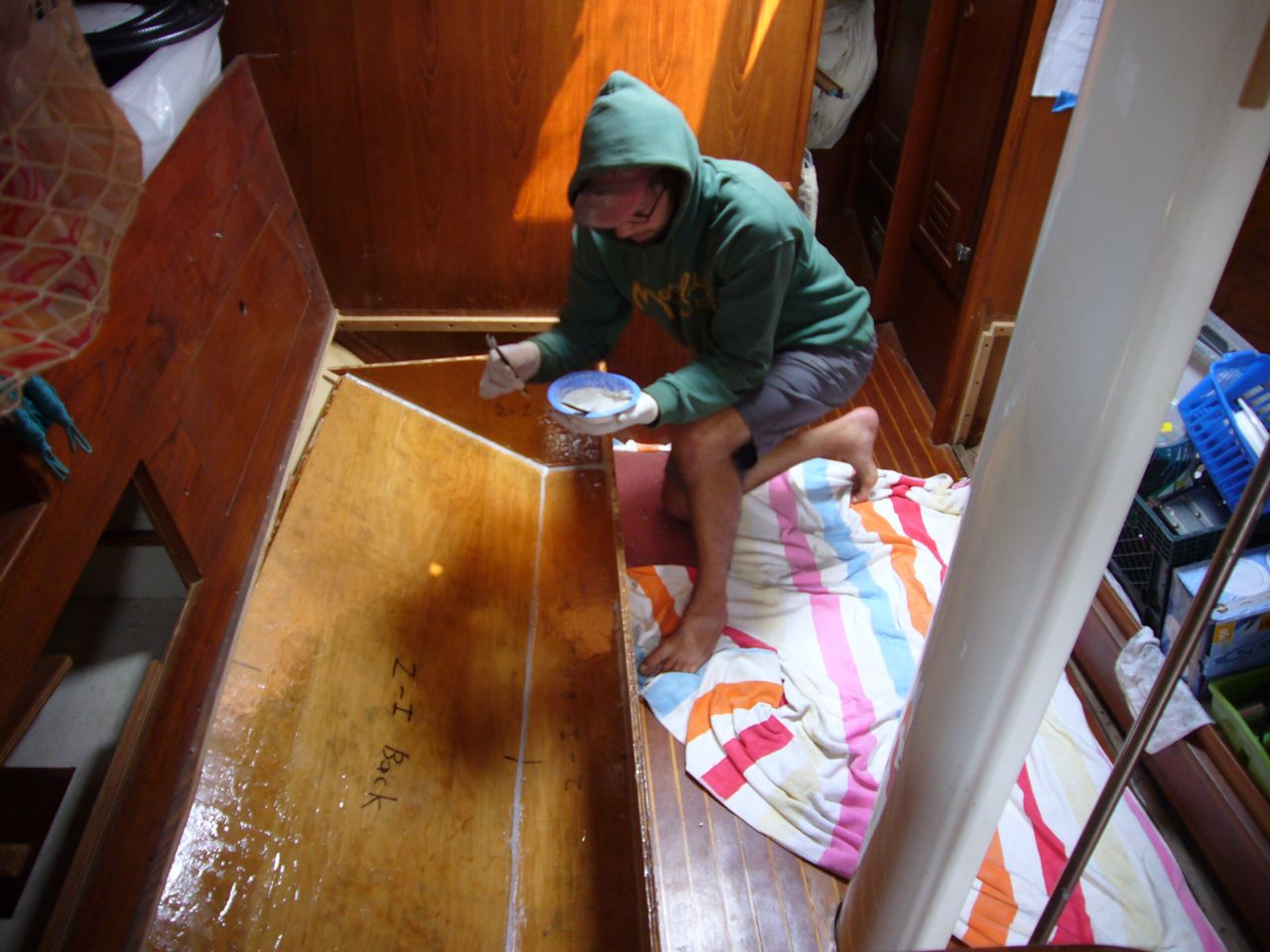
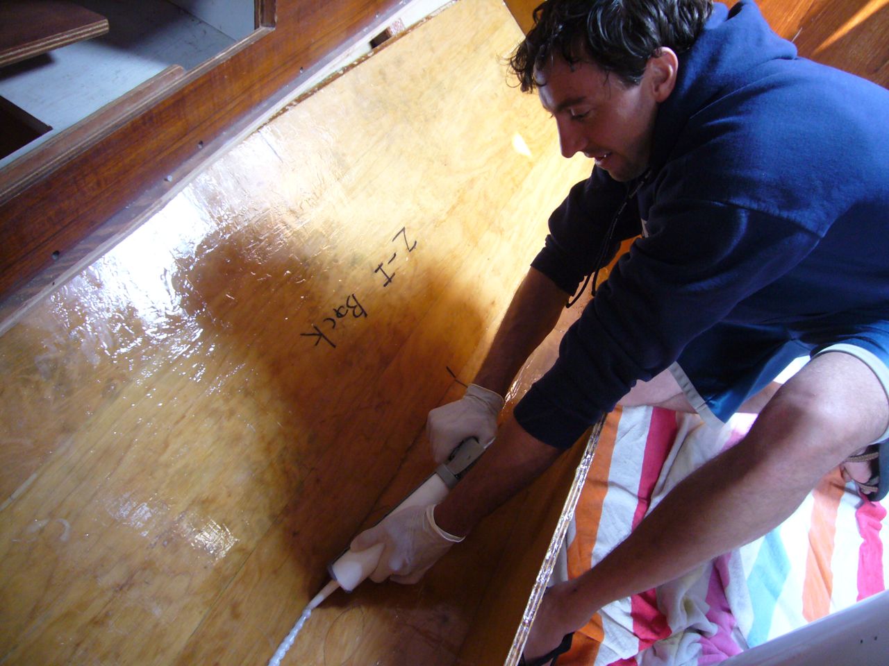
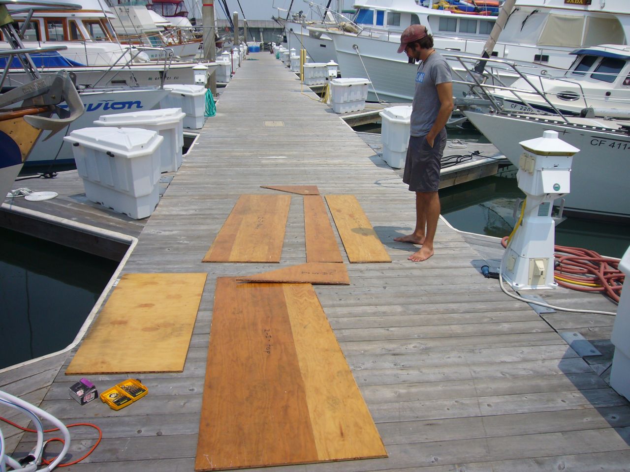
An earlier post describes the laborious task of removing the old tanks from the boat. We decided to make our own tanks out of plywood and epoxy–we figured this was the only way we could preserve the volume available to us under the settee, since the tank is such a funky shape. I had come up with this idea from some book, and found more information about it in a special bulletin from West System (they cannot, however, recommend it for drinking water storage, for obvious liability reasons). Jon and Jonny did all of the construction on the tanks, and unfortunately it required one full week of labor, all day every day, just to make the tanks. It took much more time to fit them into their spaces, construct brackets to mount them, mount the lids and seal them properly, etc. We used 3/8″ marine grade plywood. We epoxied a layer of fiberglass to all sides of all pieces of the plywood (including a baffle). We coated the outside surfaces with 3 layers of epoxy (“neat”; i.e. unthickened) and the inside with 5 layers of epoxy (all West System). We followed the instructions in the bulletin mentioned above for a slightly resin rich ratio, specifically 6 pumps of resin to 5 pumps of hardener. According to West System, it is the hardener that is the nastier stuff and that can affect the taste. After coating all the plywood pieces in this manner, the tanks were assembled with screws, leaving the lid off. Generous fillets of epoxy were applied to all seams to thoroughly seal the tank. Two holes were left in each lid for beckson ports. The tanks were brought below without the lids installed. The tricky part was making brackets that would actually fit when we went to bolt it all down–there’s not much room for error there, and there is almost zero access to the outboard brackets that are on stringers against the hull. Brackets consisting of two short aluminum angles (leftover mast steps–tumbled and anodized already) were glassed onto a small rectangle of plywood. This mounting bracket was loosely bolted to the stringer. We peanut buttered this rectangle with thickened epoxy and pushed the tank into place onto this mounting board. We did the same with the two inboard brackets at the floor. After it cured, we gently unbolted the brackets and removed the whole tank. We then glassed the shit out of the brackets before reinstalling the tank permanently in place. Finally, we epoxied the lid into place, reaching through the access holes to put the sealing fillet around the top seam (tedious and annoying step). Finally, we glued the beckson ports in place with 5200 (epoxy doesn’t stick to plastic). We used plastic plumbing fittings and mounted them in place with 5200.
With 9/16″ samson xls. The old stuff was ready to part, and friction filled. Why 9/16″? 1/2″ is plenty strong enough; the deciding factor in sheets is the size that you want to pull by hand around the winches, for comfort and efficiency. We like the heft of the 9/16″.
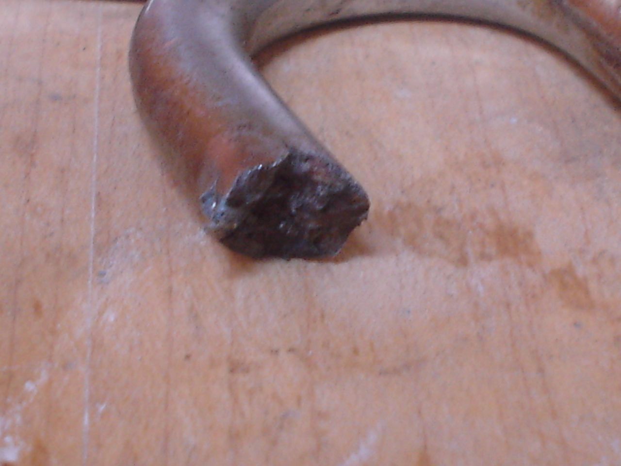
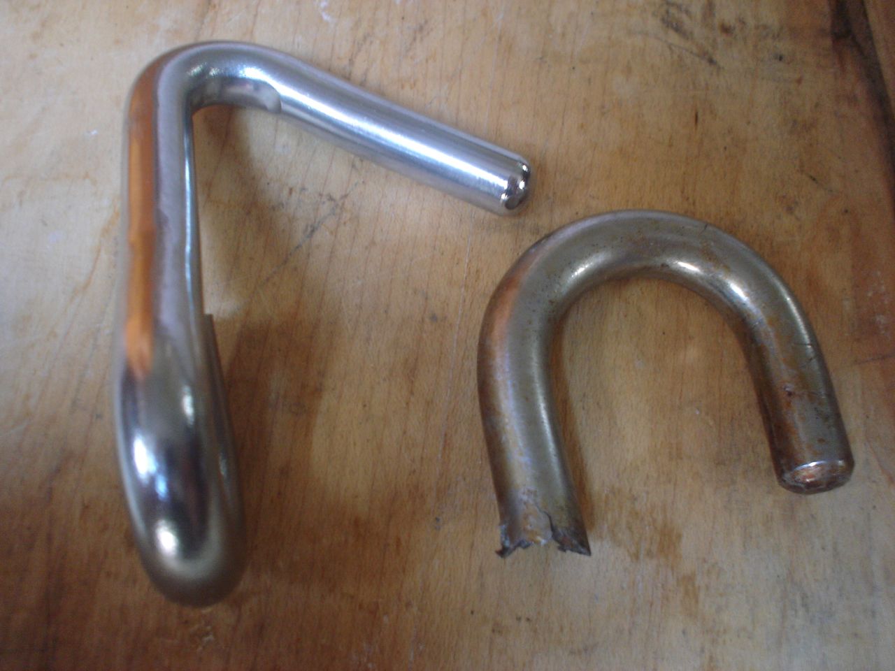
First time we went out sailing we broke it off when we practiced reefing. Metal fatigue–failed at a bend. We through-bolted two hooks to the gooseneck (one each side). Eventually we may add a system for securing the luff from the cockpit (the leech reef lines are led to the cockpit now) but that is not high-priority.
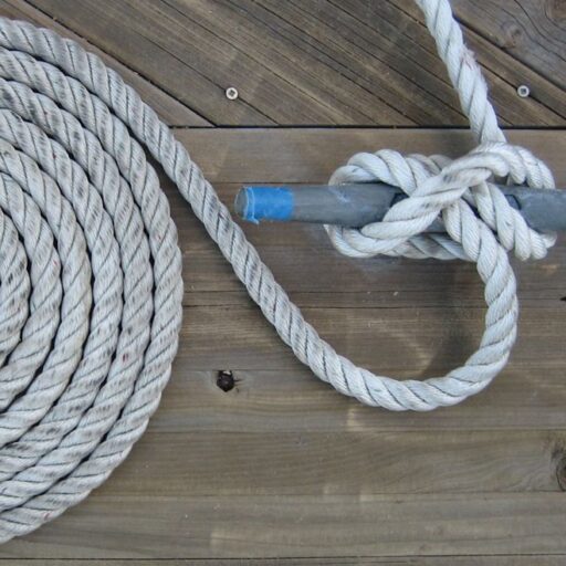
The old docklines were 4 short lengths of unmanageable dry 3/4″ 3-strand nylon; our new lines are 6 40′ lengths of 5/8″ 3-strand nylon. I bought 4 blue bumpers to supplement our deflated old ineffectual white ones.
There is way too much friction everywhere in our system. We can’t do anything by hand, and even winching in the jib is a tedious process that requires multiple rests. Replacing the lines will help a great deal.
We used 7/16″ Samson XLS for this application. We got a great deal on a spool of 500′, so many of our lines will be identical. I’m unconcerned.
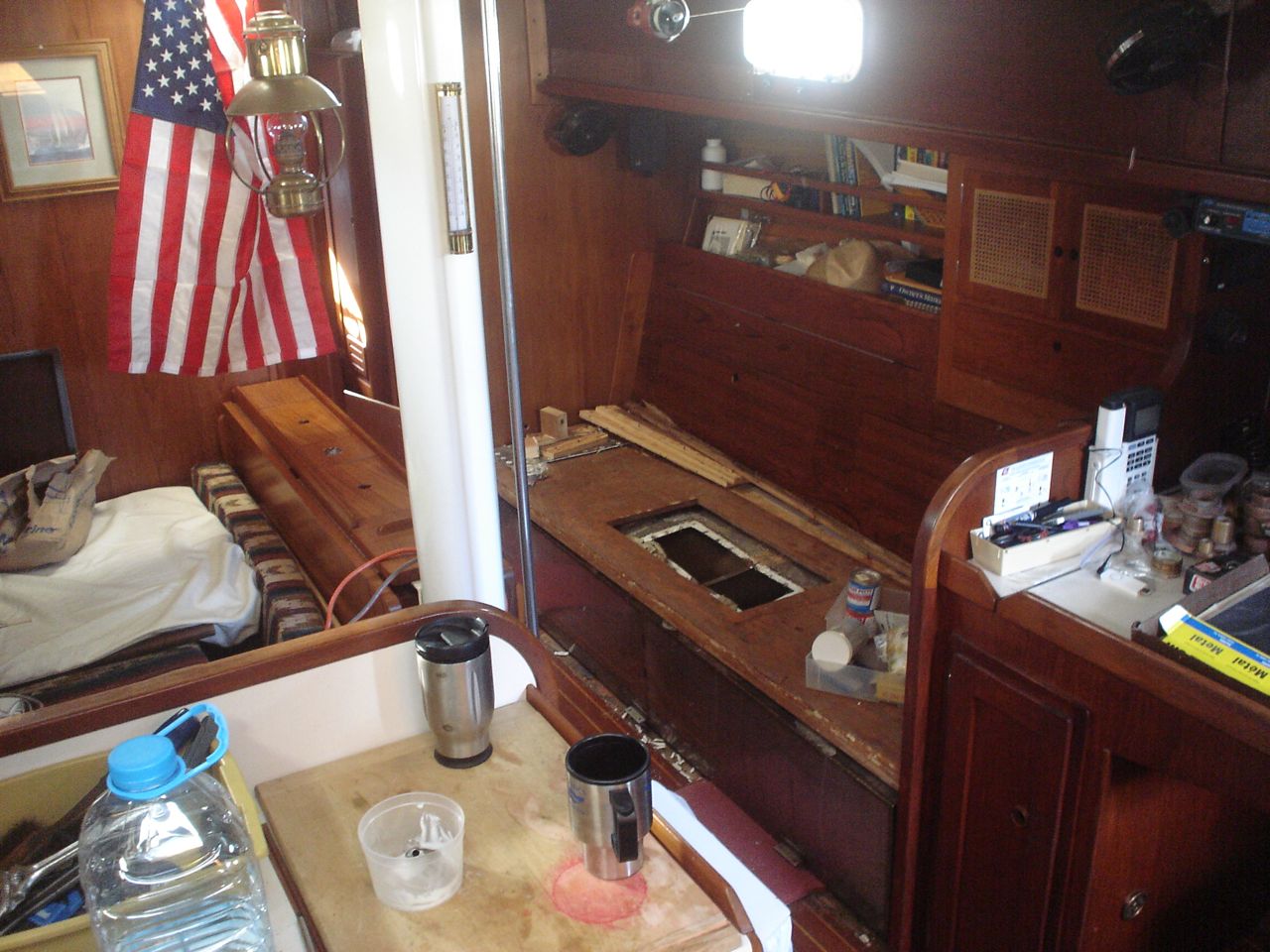
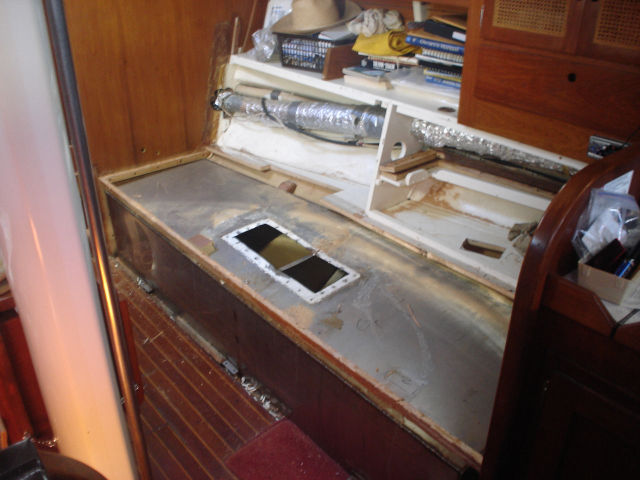
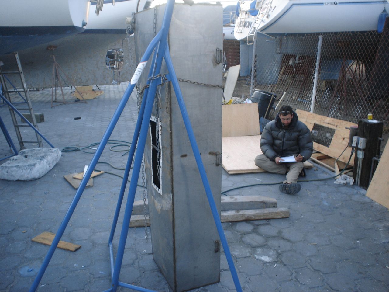
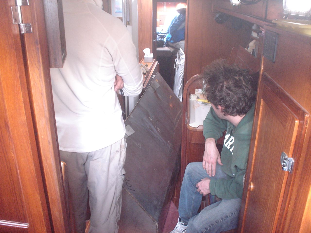
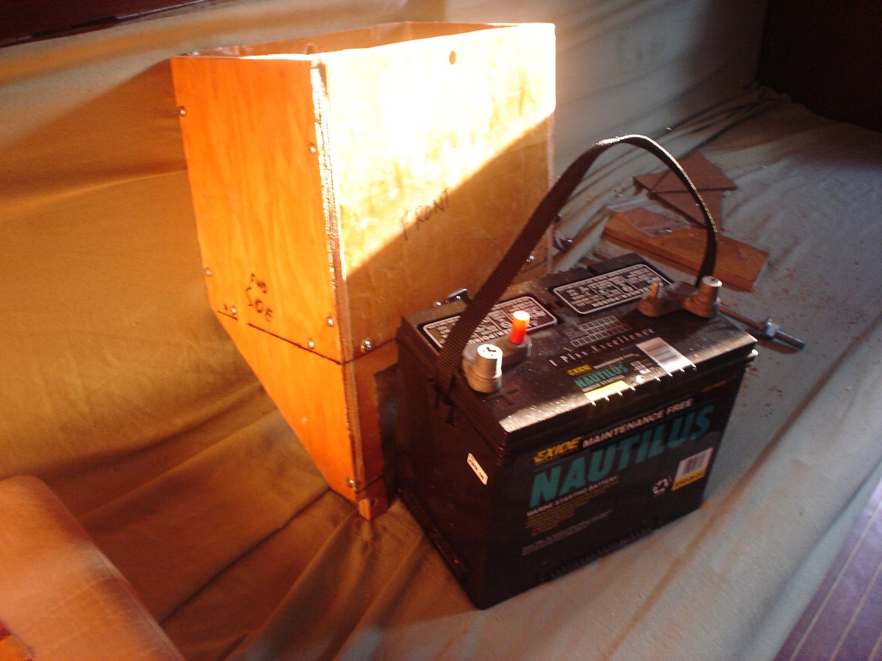
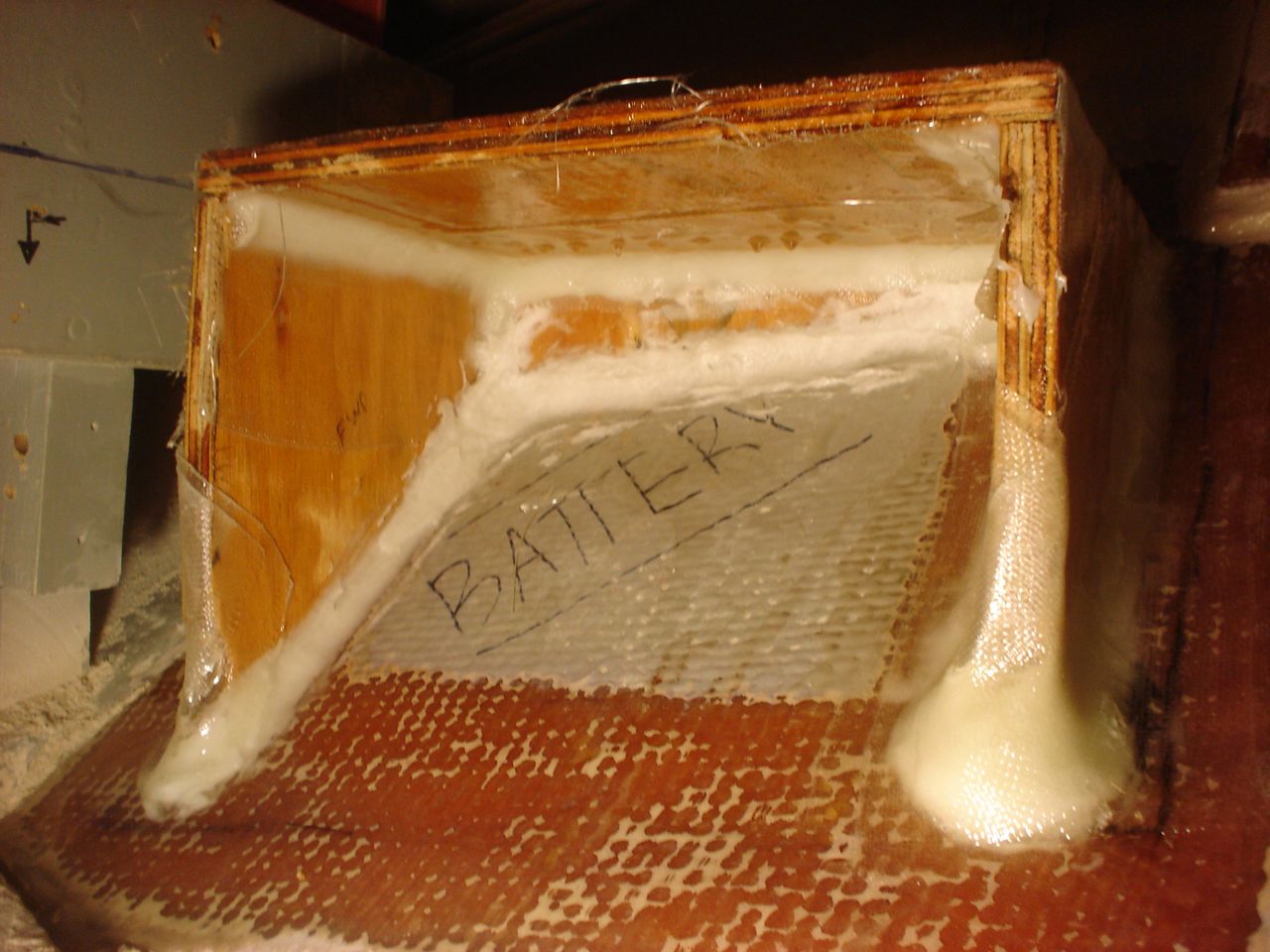
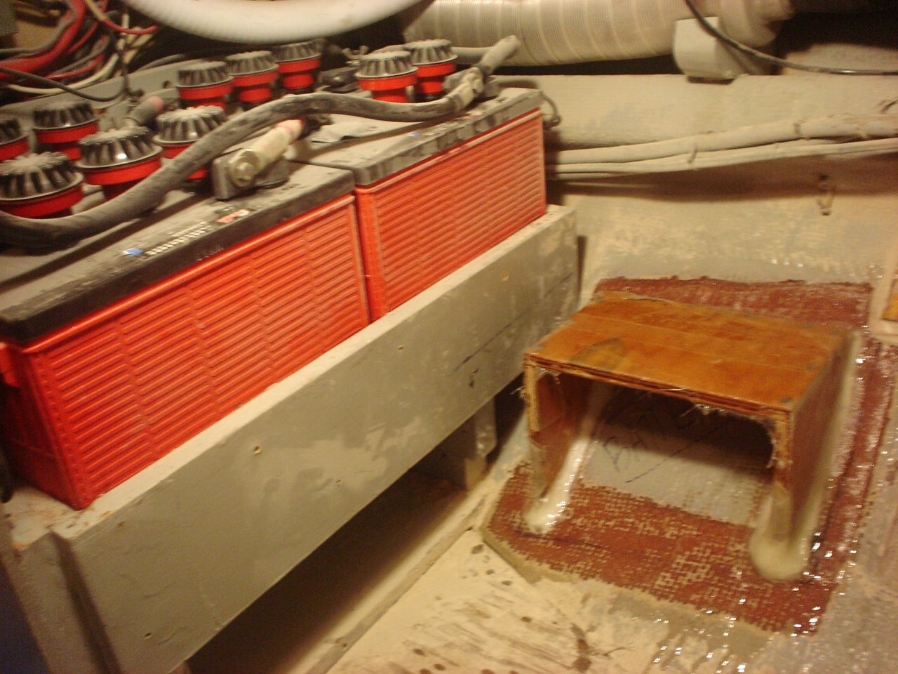
My current ongoing battle is with the electrical system. It consumes on average 40% of my time every workday. And I discover new, terrible things about it every single day. The original setup was two equal sized house banks of 250Ah each; each bank consisted of two 6V Rolls 250Ah batteries in series. This setup is not the ideal system for a boat that is trying to both maximize the capacity of the house bank and maintain the safety of a reserve supply for starting the engine while simultaneously minimizing the size, weight, volume, and cost of the batteries. Two equal-sized house banks is a common, simple, effective solution for this. But it is not the best. It is better to have a large house bank of high-capacity deep-cycle (thick plate) batteries, and a separate low-capacity high-cranking (thin plate) small starting battery. This system, though better, is more complicated for two reasons: the charging system must be more advanced in order to treat the two wildly different batteries separately, and the amount and complexity of wiring is increased. So we combined the two identical house banks into one large house bank, and bought a starting battery. Jonny built a bombproof battery box for the starting battery next to the existing house bank. We bought $200 worth of 2/0 cable to run new hot and ground lines to the engine (I put the new cable on the alternator and used the old cable for the starter).
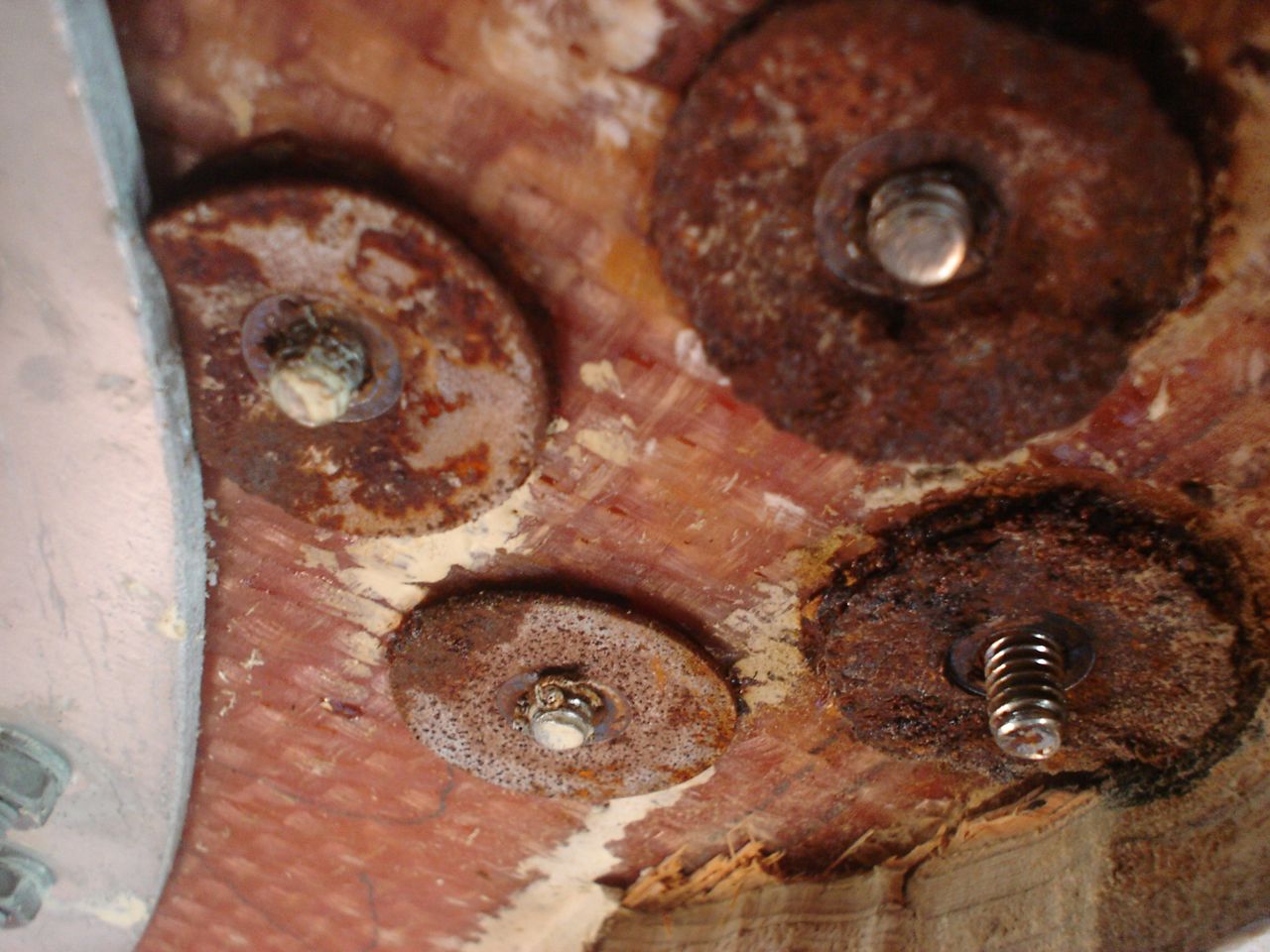
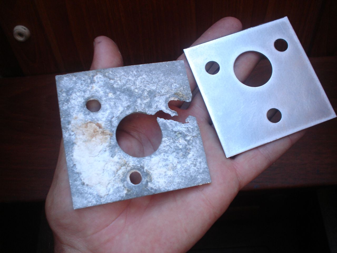
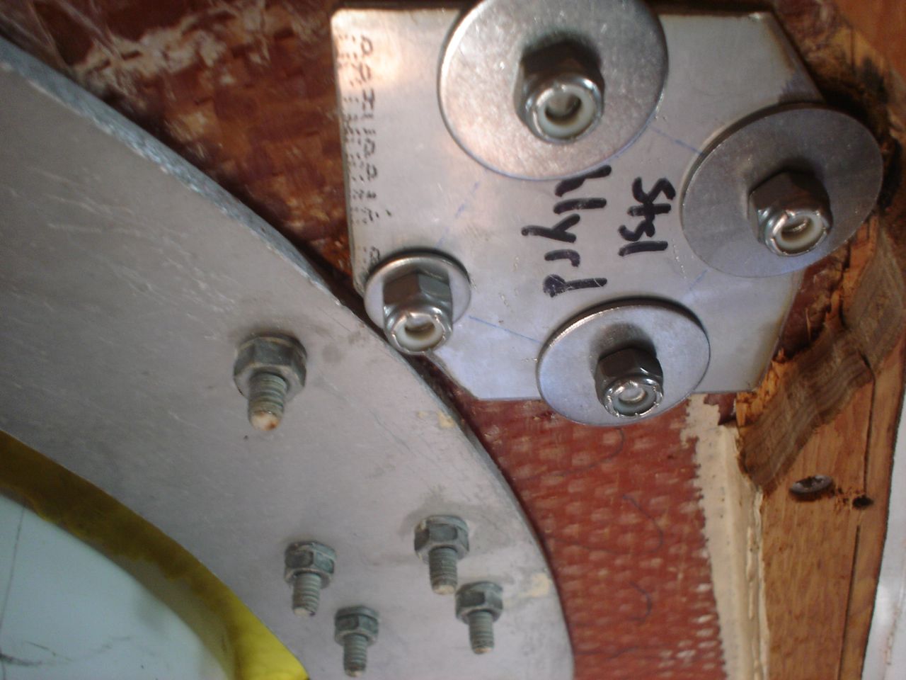
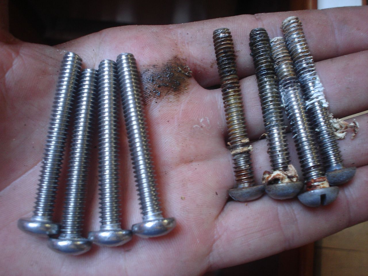
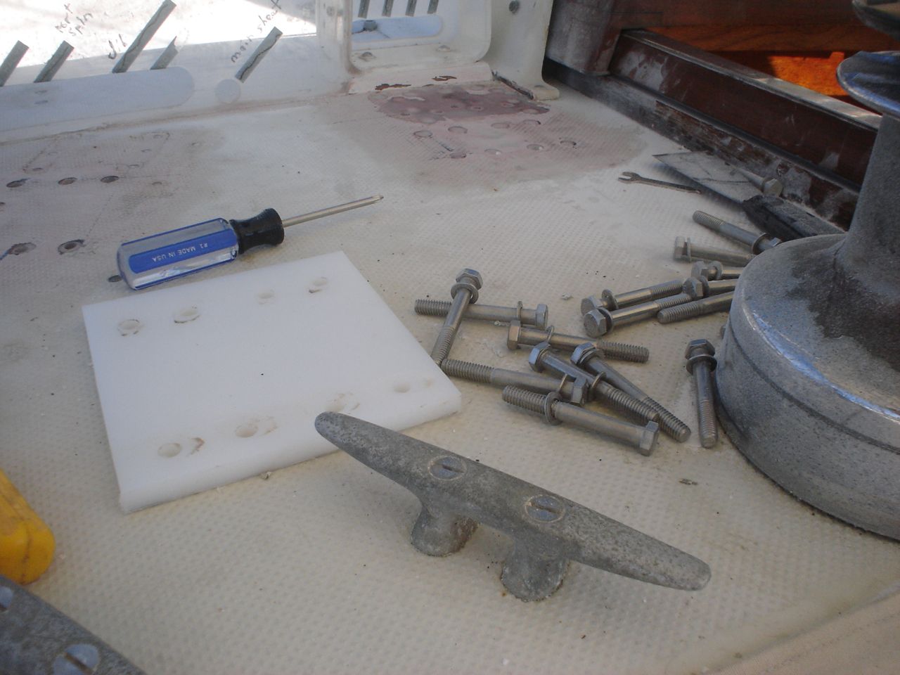
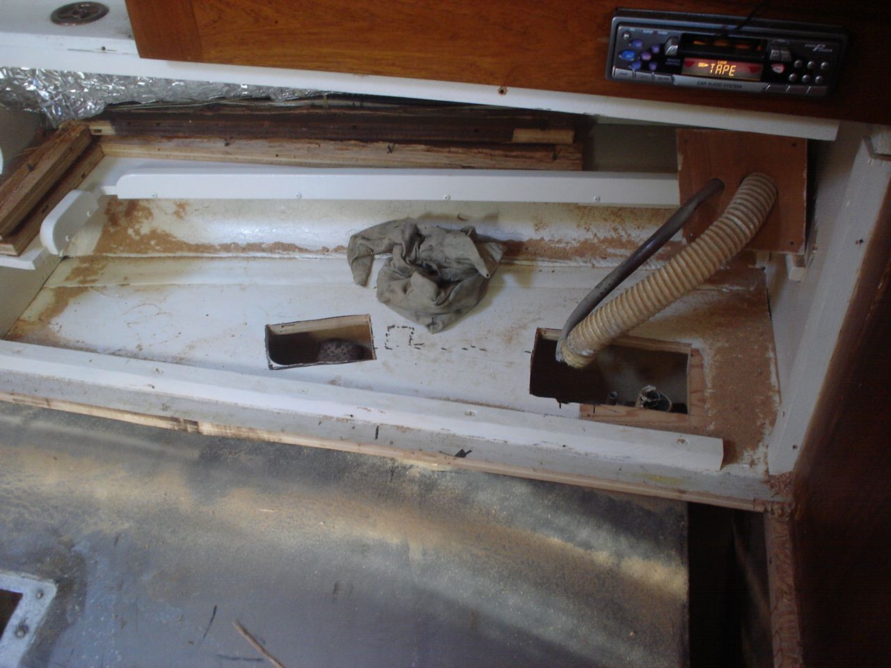
We’re discovering that many things installed through the deck are sans backing plates. The dodger was just screwed in, which in my opinion is not solid enough for how much force that dodger experiences. The staysail halyard block was backed with washers, which has rusted into powder because no sealant was used on deck. The bow pulpit backing plates were aluminum, which had so reacted with the stainless bolts in the salty environment of the anchor locker that they had corroded clear in half. We made custom 316 stainless plates for each application. In each case we also cored out the deck, filled the cavity with thickened epoxy, and redrilled for the bolts. In short, we did it the way we were supposed to in order to insure that water never permeates to rot out our cored deck. I’m willing to guess we’ll have many more of these to do–probably every time we open up a new ceiling panel. Much thanks to John Ryan for providing the stainless steel, making our bow pulpit plates for us, and giving us essential advice at every step of the way.
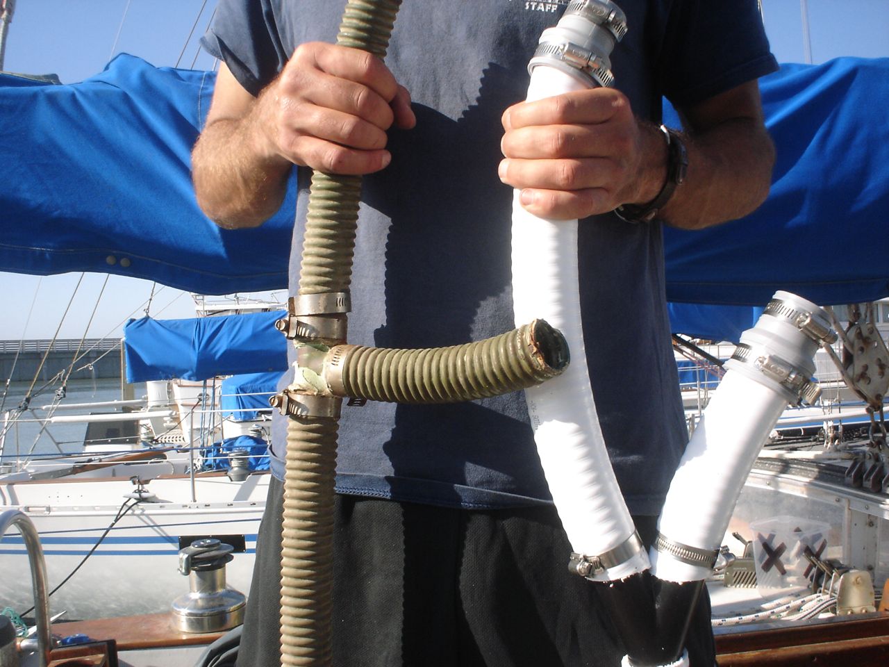
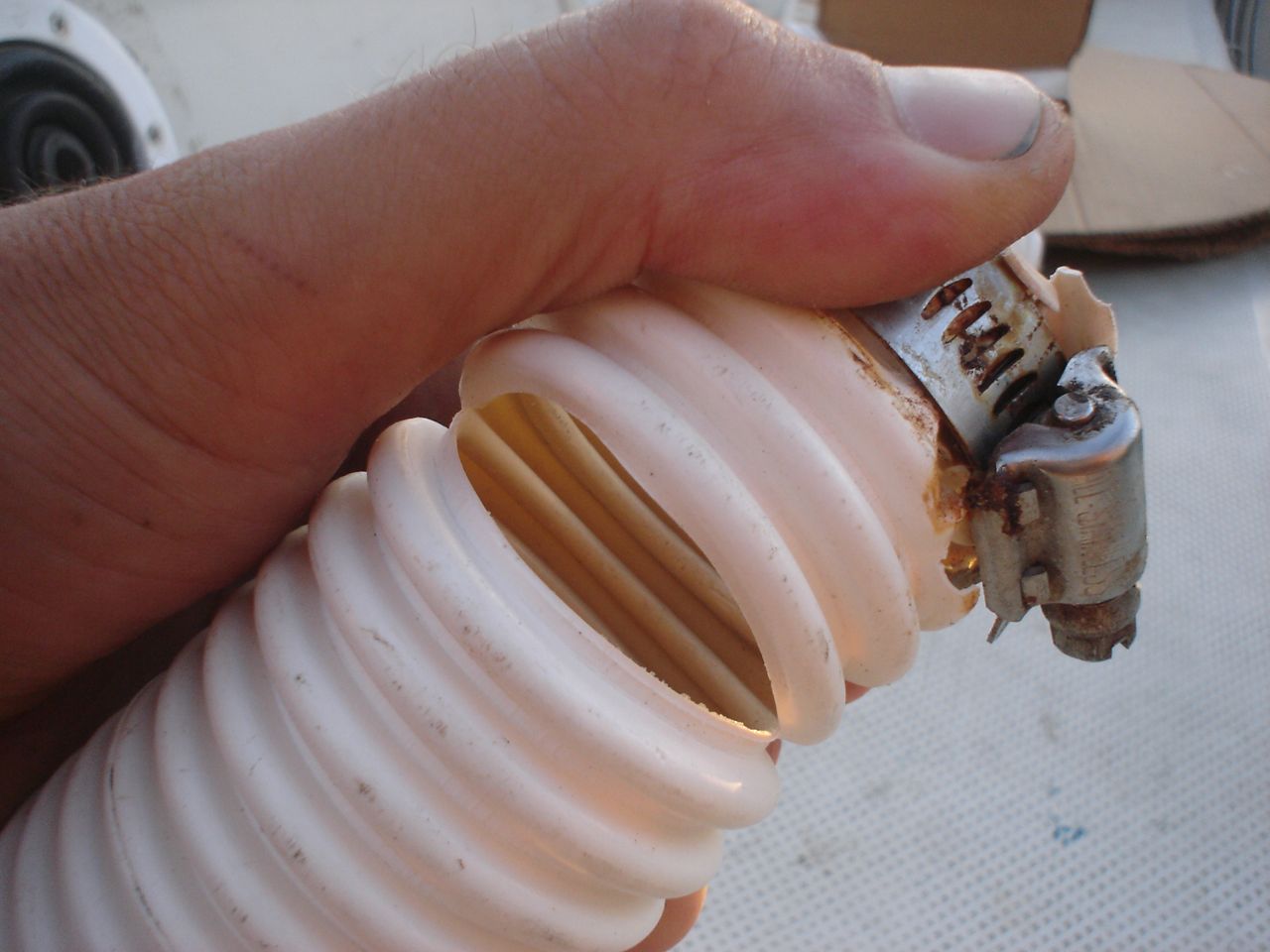
Every last one of them. We spent a fortune on hose (150 ft of Trident #148, 1.5″). Jon and Jonny did this work. The old hoses were cracked, leaking, sucking air, holding decade old bilge water in low spots–you name a form of shittiness and our hoses had it. Now it’s all fresh white high-quality hose that should last forever. The trident #148 is a smooth interior, heavy-duty white vinyl hose with a hard pvc helix for strengthening. It is marketed as a sanitation hose, but is recommended by Trident for bilge applications as well. We had a great deal on it through a friend so it made sense to go with it. The new hose was 10 times as stiff as the old corrugated stuff, so it was a bear running it. It required expansion of several holes, and all three of us to work it through the tough spots simultaneously. It just barely worked, in fact. Slightly stiffer and we may have had to trade it in for some other type of hose. But now that it’s done I don’t regret it.
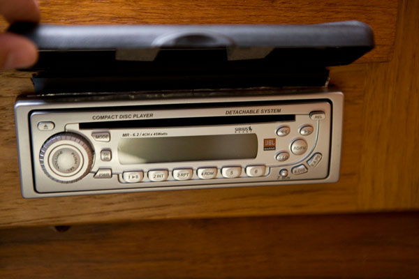
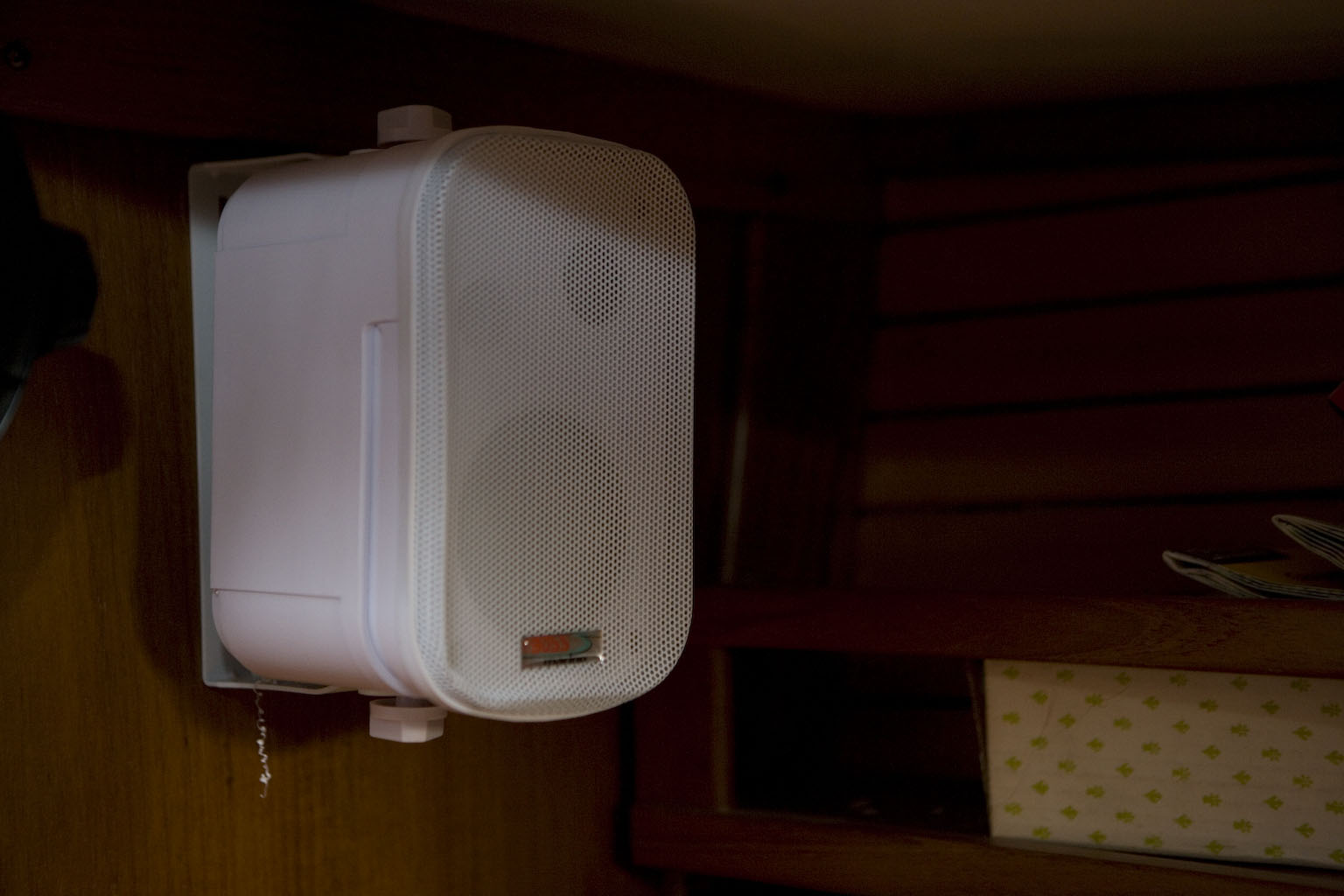
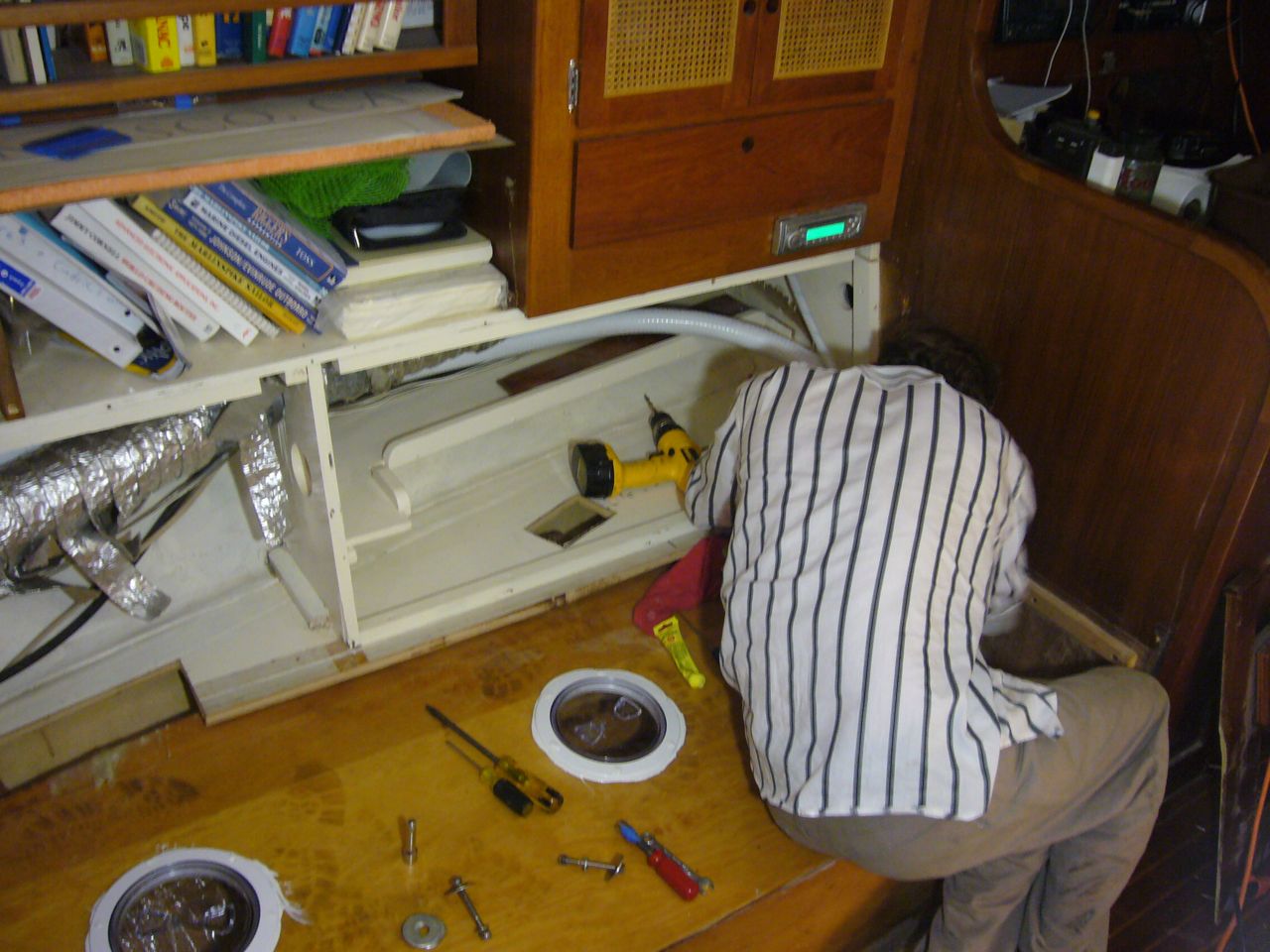
The old speakers were blown out (two in cockpit, two in cabin) and the old stereo had no auxiliary input for the ipod/computer. After tolerating a noisy tape-adaptor system for four months we elected to spring for new stuff. We bought a bottom dollar “marine” stereo (only marine thing about it was a piece of plastic across the top of it, sealing off a couple screw holes), two 6.5″ speakers for the cockpit, and two mounted box-like speakers for the cabin. We ran fresh Ancor tinned marine-grade speaker wire for all of them. I did it by the book in splicing, soldering, and heat shrinking the dozen wires out the back of the stereo, and mounted a little beautiful 1/8″ headphone jack in the bulkhead for the ipod hookup.
Mounting the speakers in the cockpit proved far more of a job than I anticipated. I had hoped that the new speakers would just screw into the old mounting holes, but of course that wasn’t the case. So we had to cut out a new ring of plywood. While we were at it we went ahead and replaced the sealing beckson port that houses the speaker.
Previously, I spent a few hours in the berkeley workyard replacing the coax connectors on the old coax, while the mast was on the ground. Well it figures that as soon as we put the mast in the boat, I notice that the old coax is completely snapped (dielectric was brittle) right at the exit hole of the mast. So we ended up replacing it after all. We bought RG-213 from Svendsen’s, which is now the replacement for RG-8U. (internet research told me that the RG-8U is an old designation no longer made, and that the RG-213 is for all intensive purposes identical). The RG-213 is thicker and higher quality than the standard RG-58x.
It was less enjoyable doing the work while hanging in the bosun’s chair at the top of the mast than when the mast was on the ground.
This time, instead of making a power-sucking butt connection in the bilge, I just ran the coax all the way back to the radio, so it’s unbroken from masthead to the radio. The next time the mast is pulled, all the bilge wires will need to be snipped and then reconnected. I deemed it more prudent to make permanent, waterproof connections (with adhesive-lined heat shrink) than to leave connectors down in the wet environment of the bilge. Now, even if the bilge fills with water our VHF and trilight should continue to function.
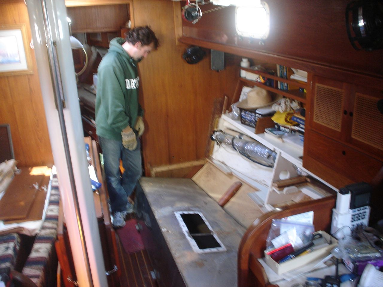
First, we chipped all the resin out of the bilge. When the boat was built in ’78 the factory poured a ton of resin into the bilge to smooth it and seal it and even it out. This was a well-intentioned but ultimately poor decision. Over the 30 years since, the resin had cracked and come unbonded from the underlying fiberglass in many places, allowing water (and more recently, our leaking diesel fuel) to penetrate underneath and hang out, doing god knows what to our keelbolts and other bilge paraphernalia. Anyway, it was nasty and not cool, and we decided to fix it. It took about 50 hours of labor, split between all of us, to chip out the resin chunks and then chip it down relatively smooth for painting purposes.
Then Jon laboriously cleaned the engine with simple green, brushes, toothbrushes, and a hose, letting the gunk drain into the bilge. As the bilge level rose, he would pump it out into large bins already in the cart on the dock, using our manual bilge pump with a hose run out a portlight. Once the bins were full, jonny and jon would cart them up to the restrooms to be inserted into the city sewer system (we were very conscious not to dispose of it into the marina water). After finishing the engine, he scrubbed and cleaned the entire bilge.
Finally, all three of us spent most of a day painting the bilge with a Sherwin-Williams “Seaguard” two-part epoxy paint. The stuff is thick as hell, and I hope that it will stick forever and ever and never flake off. The fumes were potent and we probably took a year off our lives by breathing it in such closed quarters.
It looks fantastic, and it makes us all proud. It wasn’t the most critical project, but I’m glad we spent the time and money to do it. It’s now a pleasure to do the bilge wiring and plumbing and other various work down below.
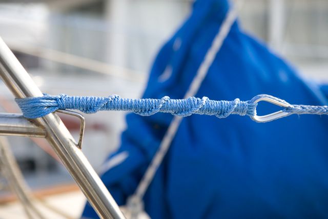
I read on Brion Toss’s forum spartalk about using HM (high-modulus) line–amsteel is my brand name of choice right now–for lifelines. This idea appeals for many reasons:
1) Much cheaper–no need to have ends swaged, no need for mini (yet still expensive) turnbuckles
2) Much easier–we can splice the eyes ourselves, and use lashings for the ends, making it simple to maintain them ourselves
3) Stronger–for it’s diameter, stronger than wire
4) Prettier–we used amsteel blue, which nicely matches our boat. It’s unusual to see blue lifelines, and it’s cool.
It took over two weeks to finish this task, working on it an hour or so a day on average. Mainly because we didn’t have all the materials on hand, then ran out of some stuff, dropped one of the latches in the water, couldn’t decide how we wanted to do the lashings, etc. But now everything is finished and we’re satisfied with the result. My only concern is that the blue is going to wash right off the amsteel, and then it won’t look as cool.
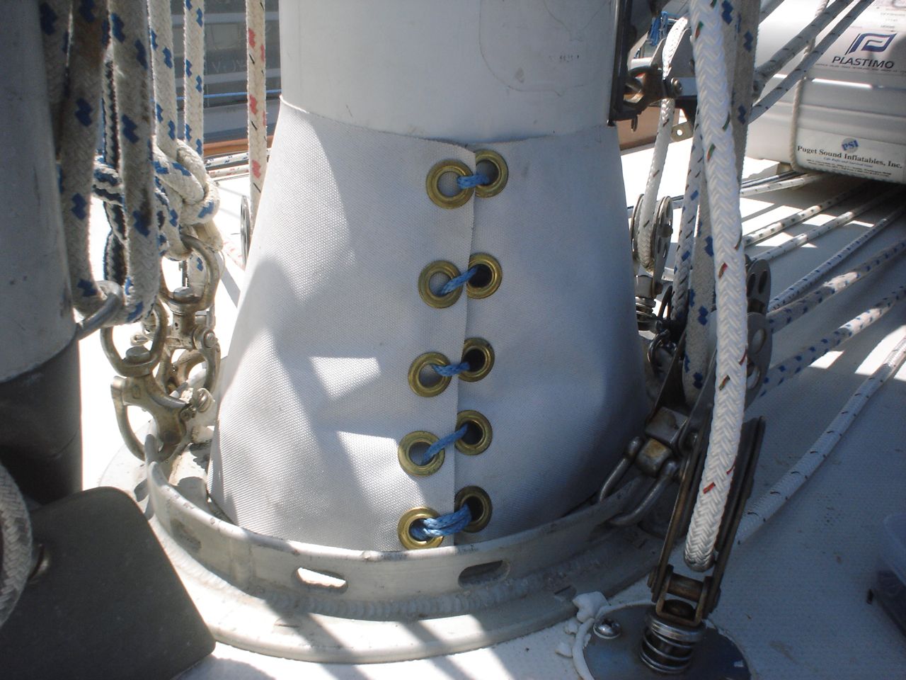
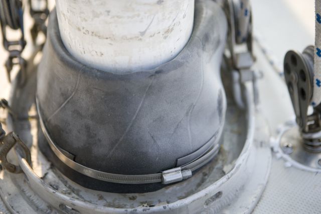
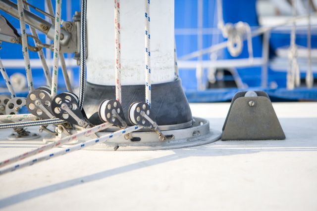
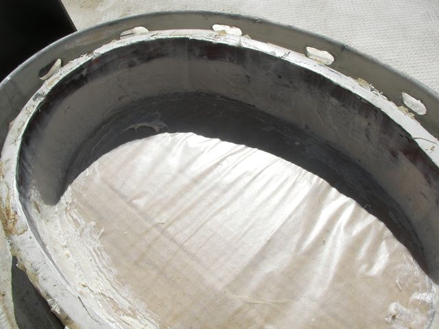
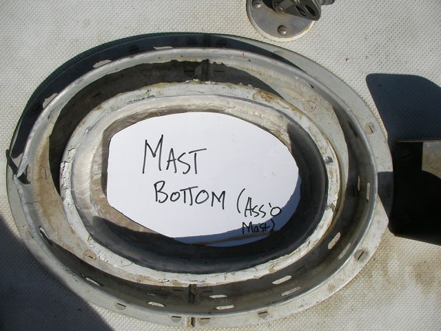
It took us a few weeks after the mast was stepped to finish the job. First we needed to tune the mast in the boat. To start with, the mast was rotated slightly; not aligned with the centerline of the boat. Jon went up to the spreaders with a tape measure and we tried to measure from the spreader tips to the backstay to assess the rotation, but it became clear that the method wasn’t working. So instead Jon went into the bilge and eyeballed the shape of the mast on the step (which is perfectly contoured to the mast base) while I used the disconnected upper shroud to wrench the mast around. It was somewhat disconcerting to be rotating the whole mast without much control. After we got it rotationally aligned, Jon went back up the mast to the top, and we measured from the top to the chainplate on each side, and I painstakingly adjust the uppers (all other shrouds slack) until we got the exact same measurement on each side. So then it was centered at the very bottom of the mast and the very top, but at the deck it was deflected to port by 3/4″. Fortunately, when we pushed on the mast at the deck it readily flexed, so we bowlined a line around the mast, led it through the jib fairlead and back to a winch, and a small amount of force pulled the mast into precise alignment. Then we used a pound of modeling clay, obtained at our local Michaels, to create a floor for the spartite. In truth we didn’t use spartite, but rather the generic McMaster-Carr equivalent (part no: 8644K18) for half the price (on the excellent advice of Bryan Genez). It is a “flexible urethane casting compound”. We used two one-quart containers, $32.33 each, and it was the perfect amount. A momentary digression: the original shape of our mast partners was not conducive to a spartite application so we modified it. The shape of the valiant mast partner is an inverted cone–if the spartite is applied without modifying the partners, the plug will never come out of the boat when the mast is pulled–it will have to be cut out, negating half the benefit of using spartite in the first place. I corrected this by filling in the void area with epoxy thickened with high-density filler (thick like peanut butter), to make the internal surface of the partner vertical and smooth. In retrospect I wish I had even formed it into a slightly upward shaped cone, just to be sure that it will come out easily, but I think it will be ok. Pouring the spartite was fun (mostly because it was easy). We let it set for about 4 days before removing the line that was centering the mast and tightening the other shrouds. Then we constructed a mast boot from a thick tire inner tube. We followed the instructions in one of the books I have, offshore passage-making tips by bill seifert. It involves two large hose clamps and some rubber glue. Cheap, easy, and effective. As a final touch, Jonny made a canvas cover for the rubber boot to protect it from the sun (sorry there’s no picture of this).
cardboard to provide bottom edge for epoxy fairing
detail of fairing the mast partner with thickened epoxy
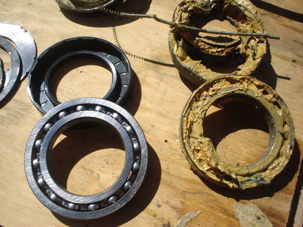
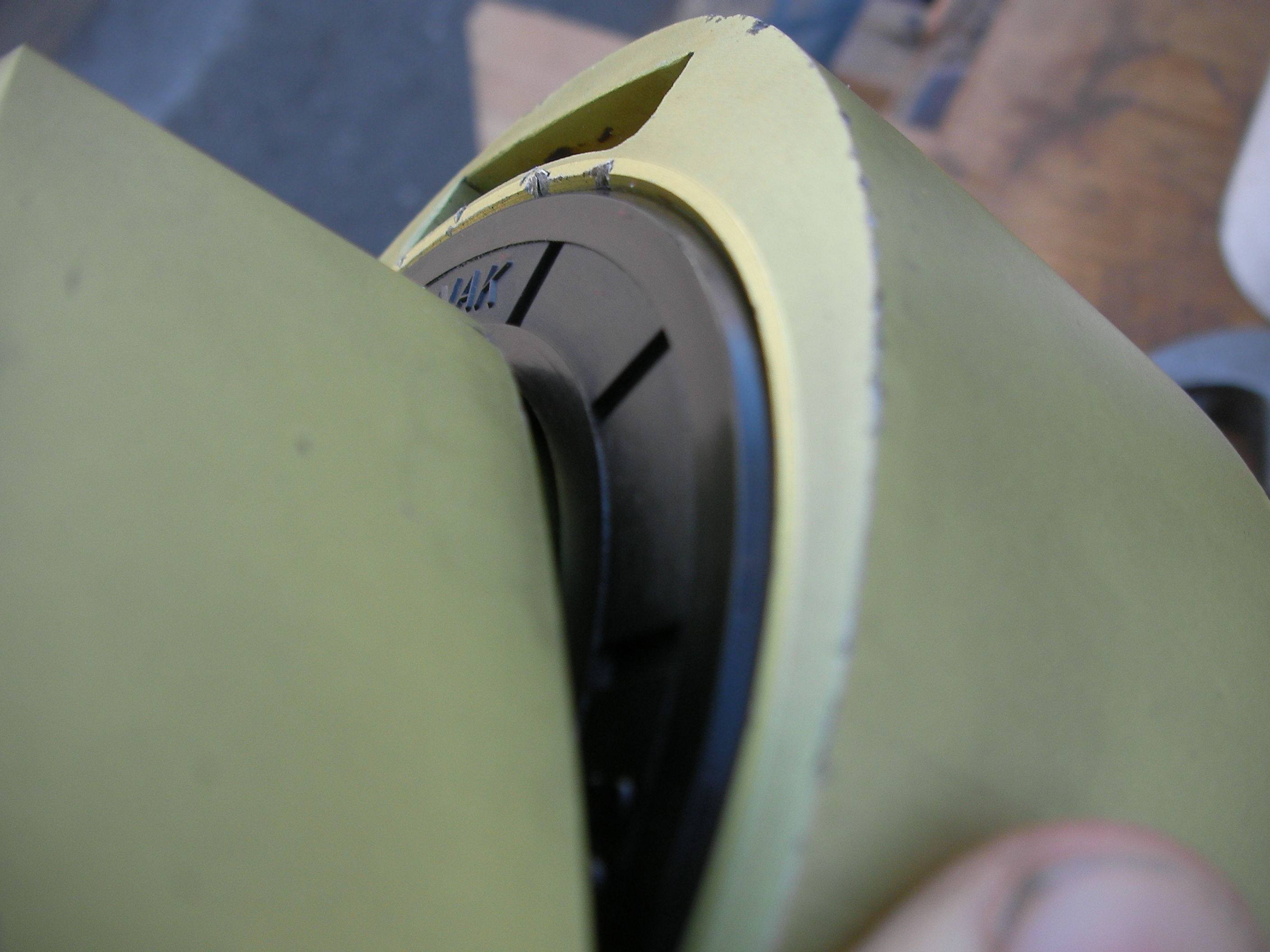
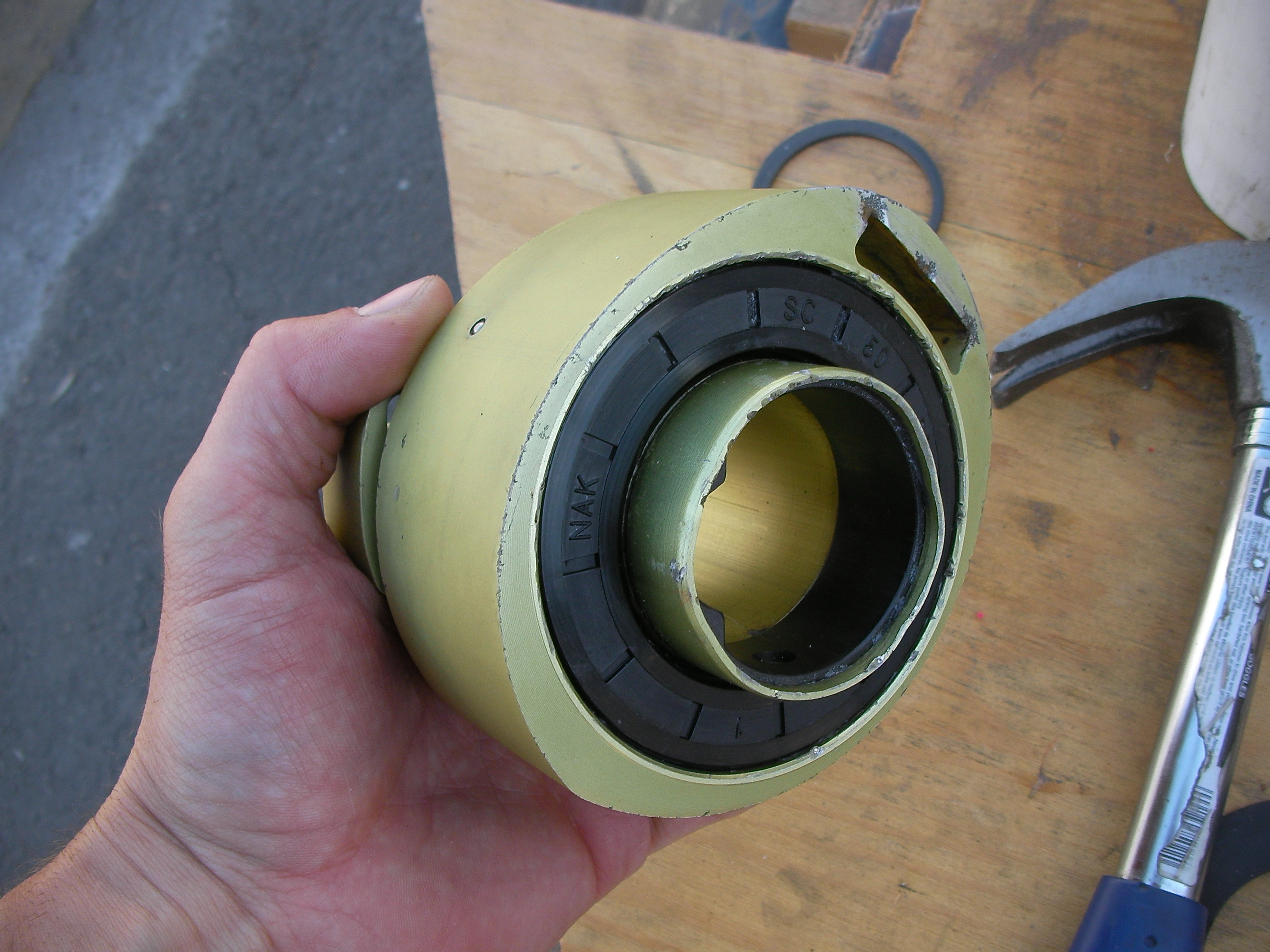
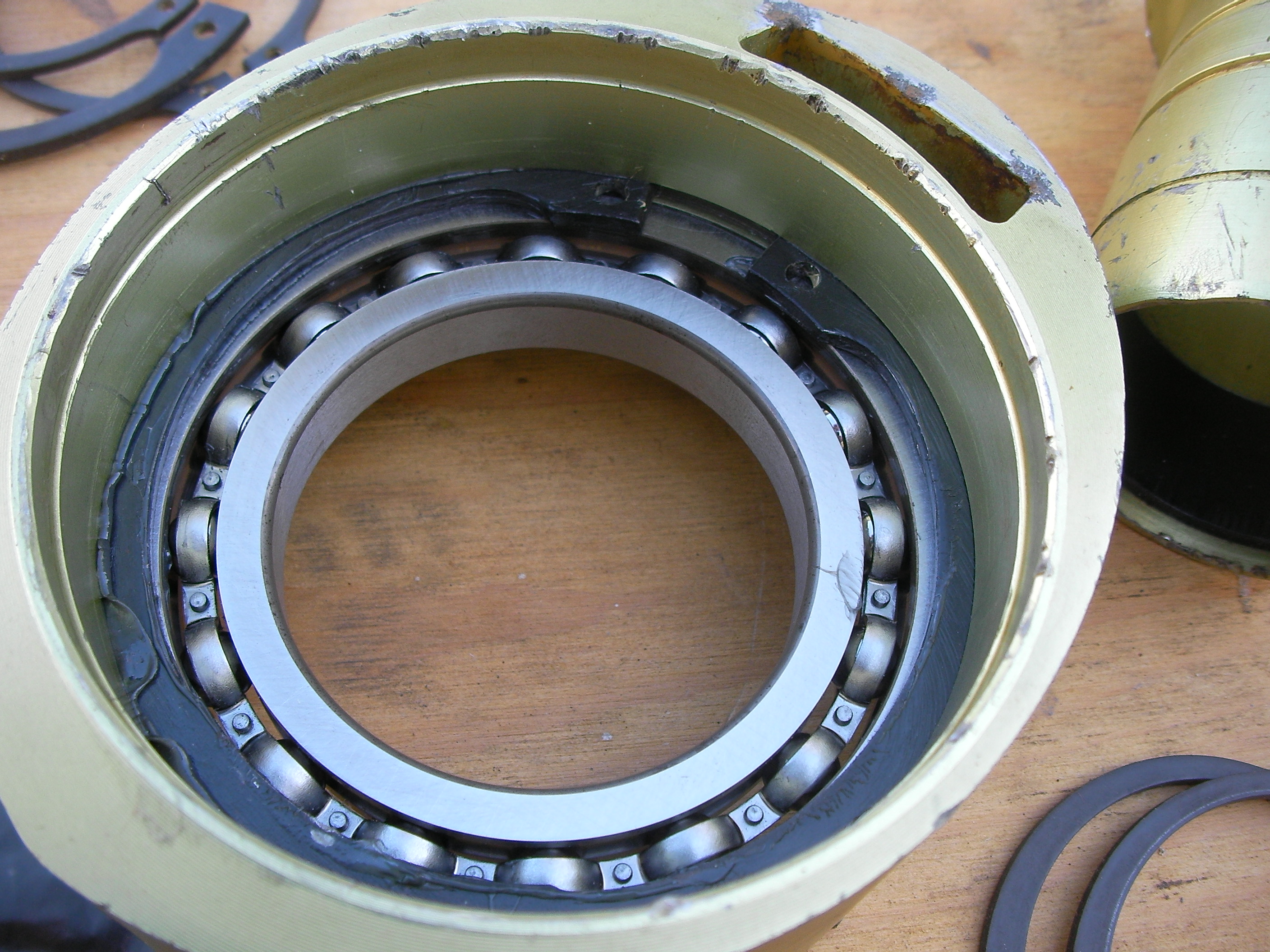
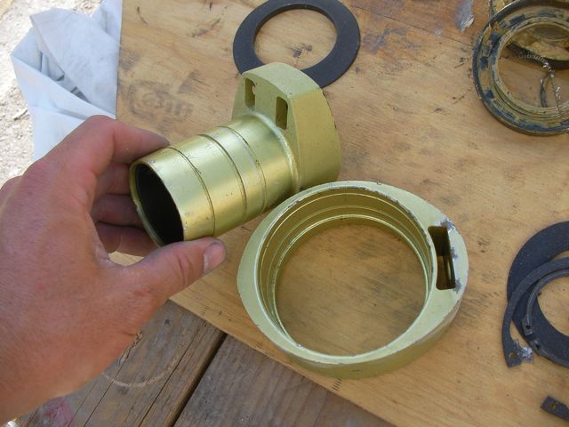
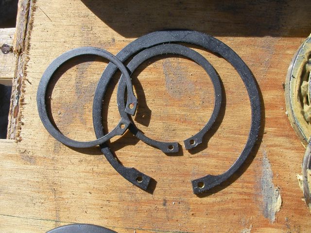
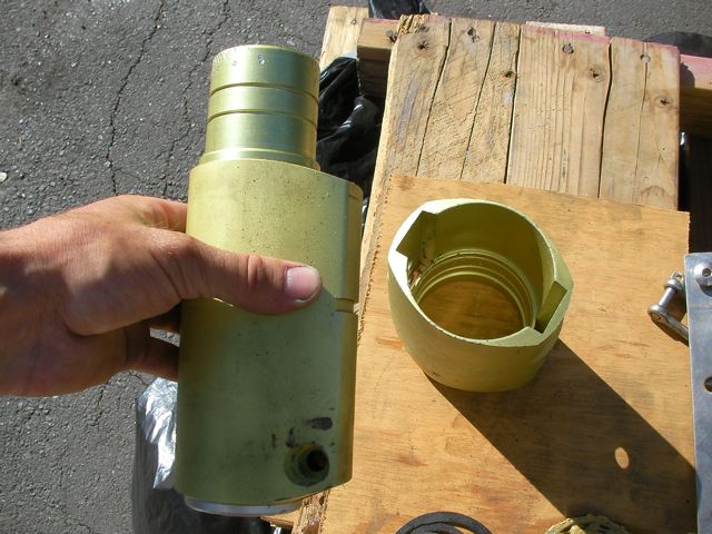
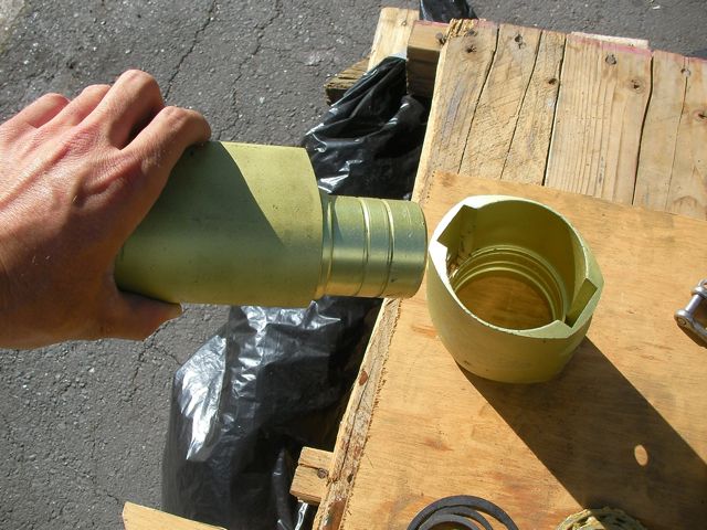
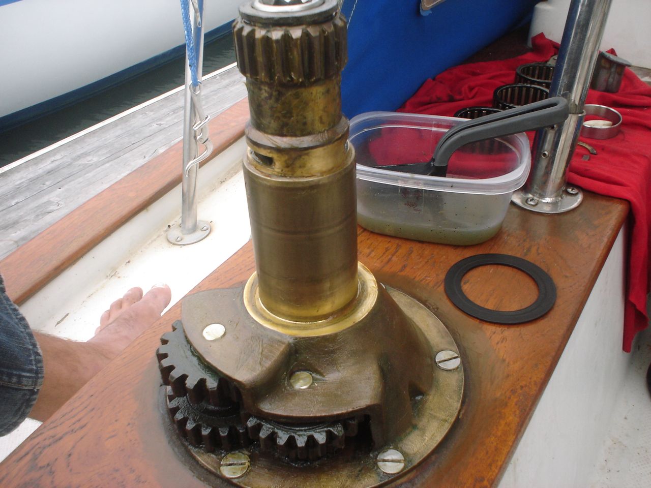
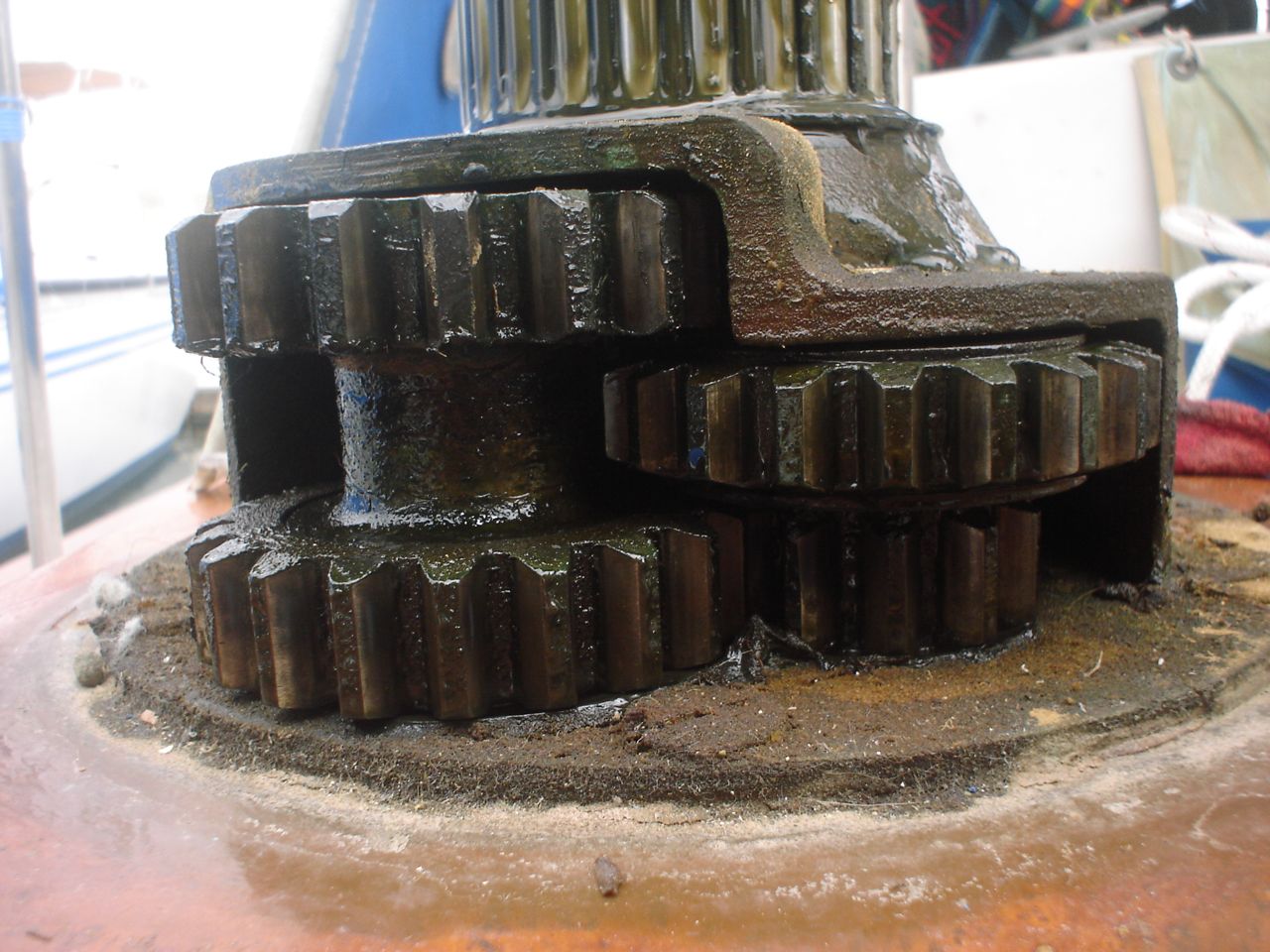
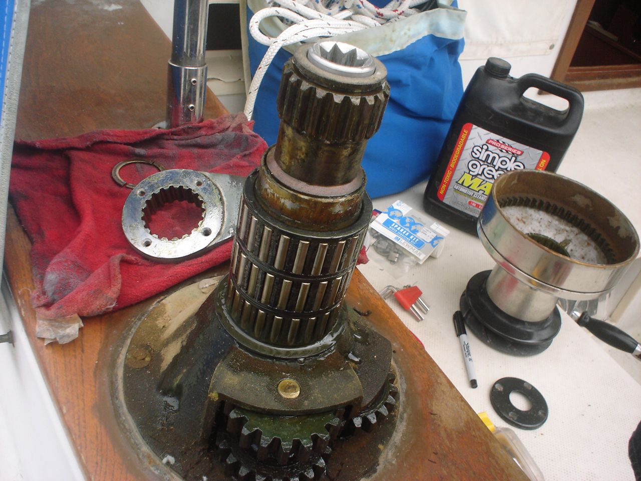
The Profurl has sealed bearings and supposedly cannot be serviced (throw it away and buy another is the policy among riggers). I found a site on the internet that explains how to do it, what parts you need, and what tools you need. I am very thankful to Andrew Bray for posting this information, and also Chris Zinger who wrote up super detailed instructions (available through Andrew Bray via his website). Without their pioneering efforts on this project, we would never have been able to do it. They are gentlemen and sailing scholars, and I salute them. The hardest part was pulling the seals out. We tried the methods described, but to no avail. In the end we used the dremel tool to very carefully grind away the steel ring that exists inside the nitrile rubber seals. Fortunately, we did not damage the sealing surface using this method (we had damaged the sealing surface already, before we knew any better, trying to pry back the edge of the seal with an awl to get grease in/out–damn–oh well).
Jonny sanded the starboard side, I sanded the port side. That took a day, and was tiring work. We used the yard’s special vacuum sanders ($15 rental/day) which are required by law to help suck up the toxic old paint. We went through a dozen 80 grit pads. I spackled our keel fiberglassing projects with QuikFair, a really great two-part filler designed exactly for this task, and sanded it fair afterwards.
Then we painted over all exposed fiberglass (from our various keel/through-hull projects), and the bronze skeg shoe, and the bronze shaft strut, with 4 coats of Interlux Interprotect 3000E epoxy primer. It is high build (read: thick). It is my hope that this will both seal the fiberglass and help paint stick to the bronze.
Then we applied 4 coats of Pettit Premium Antifouling Bottom Paint. It is an ablative paint, which means that it sheds off over time. The previous paint was an ablative, and you can’t put a hard paint over an ablative, and we weren’t going to sand all the way down to the barrier coat, so it was an easy choice to pick an ablative. The “Premium” that we got is one of the cheapest bottom paints available ($75/gallon); Practical Sailor gave it a best buy, and after reading a lot about the different bottom paints, I couldn’t shake the feeling that the expensive stuff is a hoax. We bought 4 gallons, and used 3.5 to do the 4 coats. Jonny and Karen did all the painting 🙂 lucky me.
Four coats is maybe a bit excessive (most people do 2 or 3 at most), but we’re not going to save the paint for next time and the paint works by wearing off over time, so the more the better, right? We didn’t bother trying to make it super pretty, but it came out pretty slick regardless.
The old hole was on the port side, which is the inaccessible side of the mast in the bilge. Jonny drilled a new hole on the starboard side; the edges were filed nicely to create a soft edge for the wiring to exit.
The old drainage at the base of the mast was a single hole, approximately 1/8″ in diameter, about 2″ above the base of the mast. This was corroded and plugged when we pulled the mast, and the base was filled with dirt and aluminum corrosion. Jonny used a cutoff blade on the grinder to create a narrow slot from the base, reaching up to the old hole. This should do the job much better.
The wiring that comes out of the mast includes: 1) VHF coax 2) mast head instruments: wind speed and wind direction 3) masthead trilight 4) steaming light/deck light combination fixture
I redid all the connections in the bilge and some of the wires that run the length of the mast. The old connections in the bilge were wet and soggy when I unwrapped the ancient electrical tape that was “waterproofing” them. I soldered each of the wires directly (i.e. direct splice, no butt connector), put a heat shrink over each of the individual connections, then put a large heat shrink over the whole group.
VHF coax connectors: The old ones looked heavily corroded, so I cut off as much coax cable as I dared in an attempt to expose fresh, uncorroded foil. The coax was pretty manky and I didn’t feel great about it, but I didn’t want to pay for 50ft of new coax to pull up the whole mast. This was unfortunately not as successful as I hoped–I ended up soldering the new connectors onto still pretty corroded foil. Then we got a deal at ancor on new VHF coax, so I ended up redoing it again after the mast was in the boat. Poor timing on my part, but it worked out alright. I ran the new cable all the way to the back of the radio, so there is no connector in the bilge as there was before (this is preferable, since there are substantial losses in signal power at every connection). The next time the mast gets pulled, the coax will have to be cut in the bilge and a connector installed.
When we bought the boat the steaming light did not work. It was a wiring failure in the connection located in the bilge. But I decided to examine and potentially rewire the fixture anyway.
There were two additional, unused three-conductor cables in our mast. I do not know why they were installed without being used for anything. Regardless, we used one of them for the new trilight, and the other one we pulled partway back down the mast and I used it for the steaming light fixture. I now have complete confidence in the electrical connections.


")