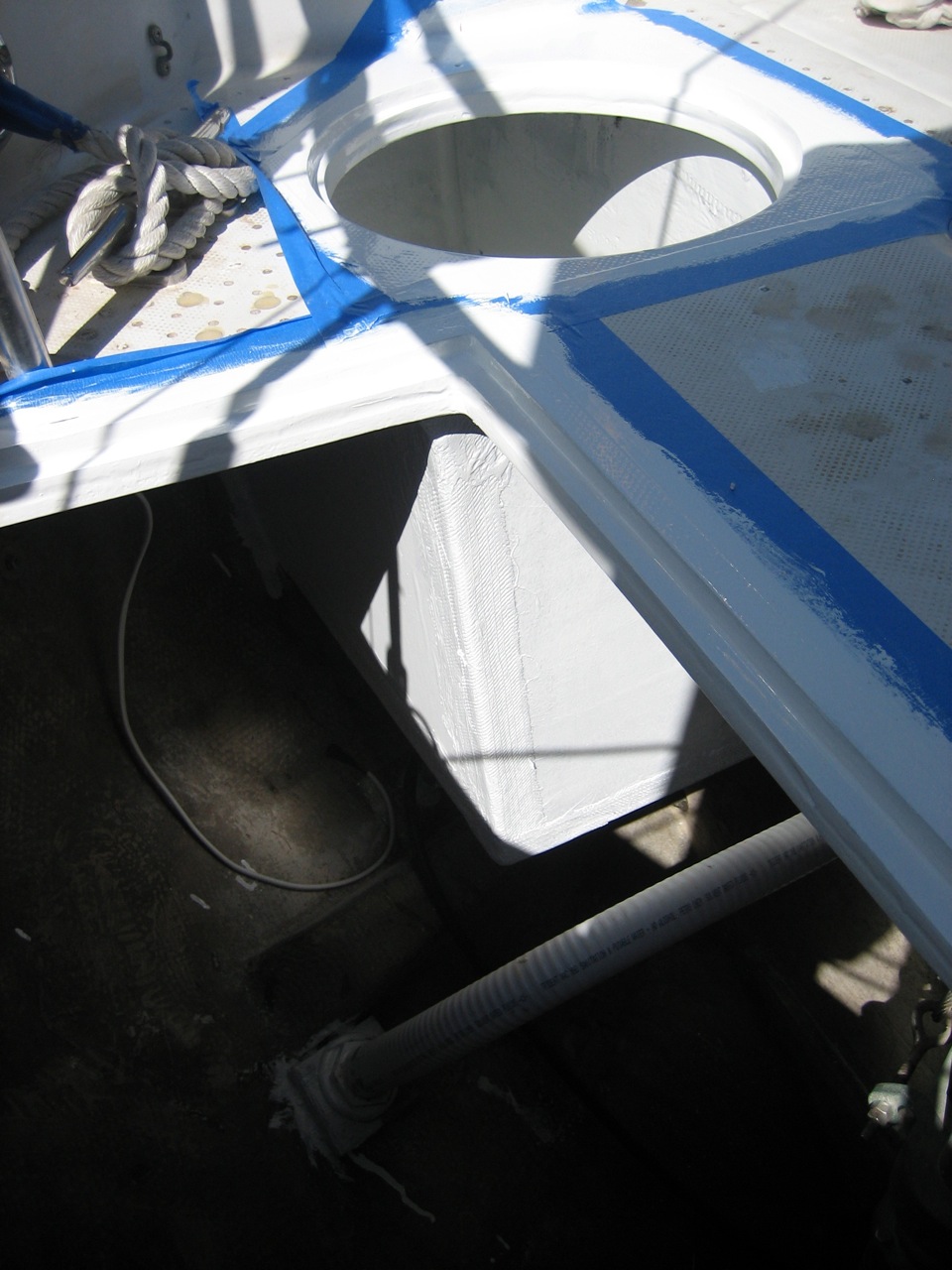
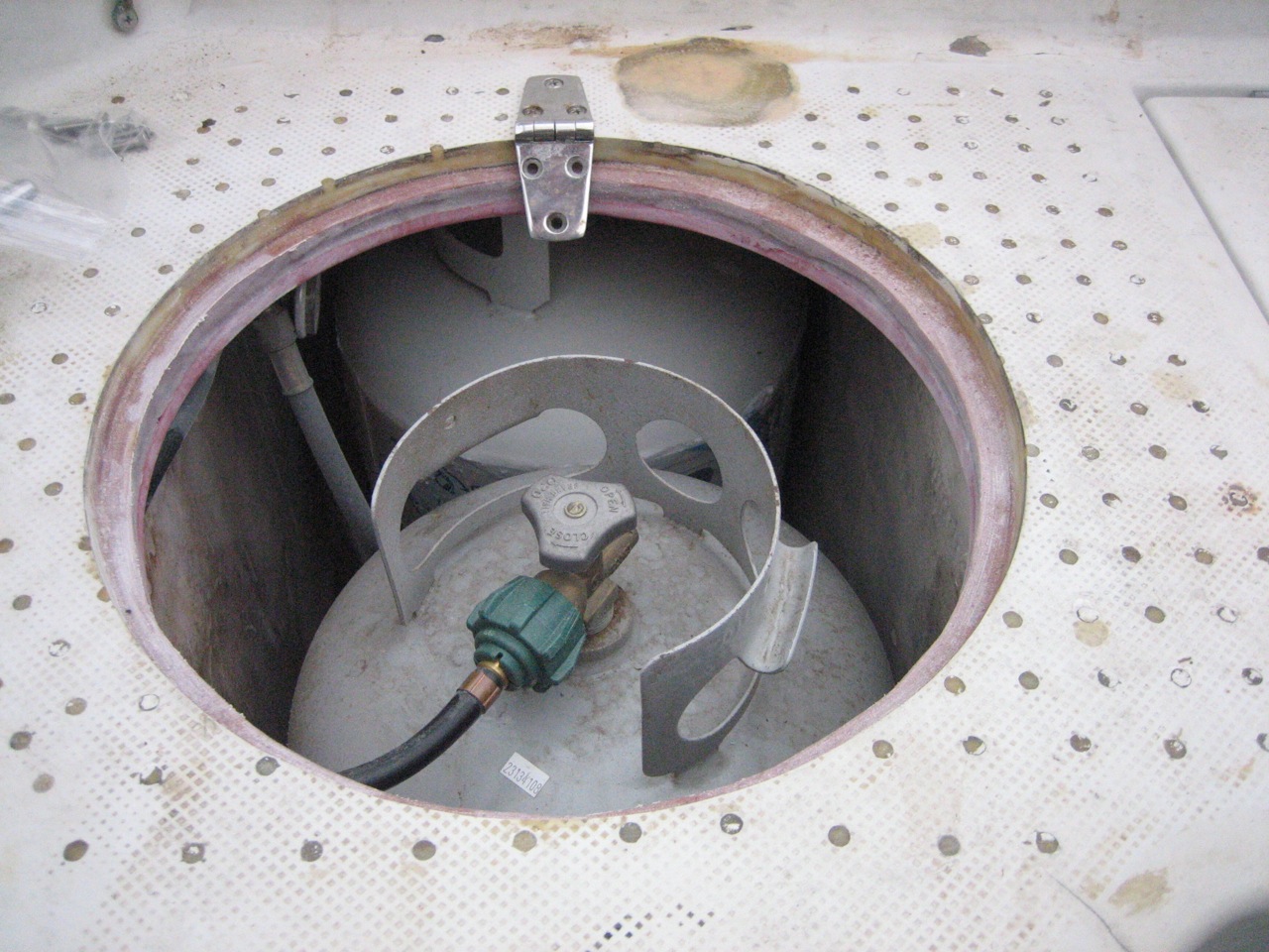
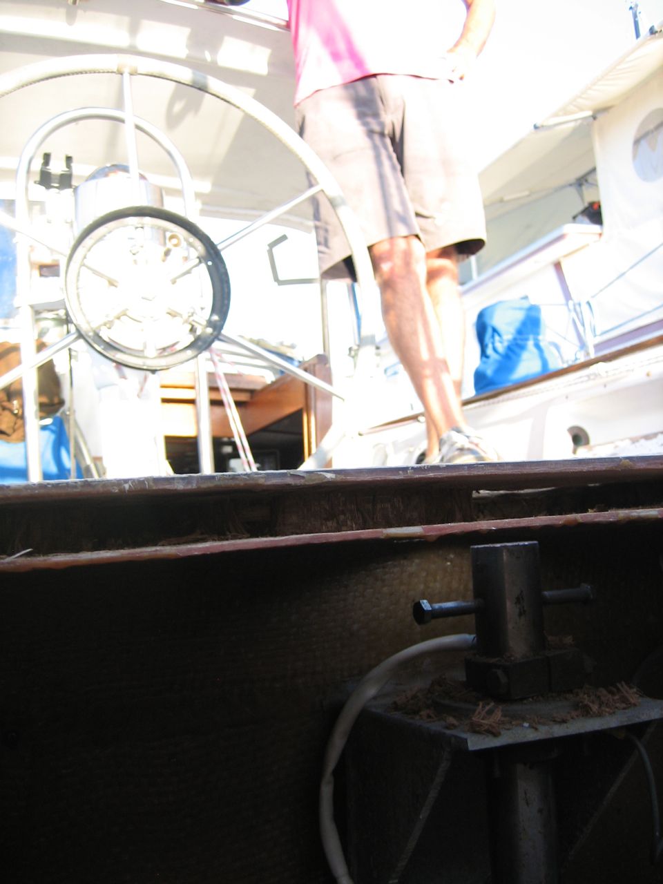
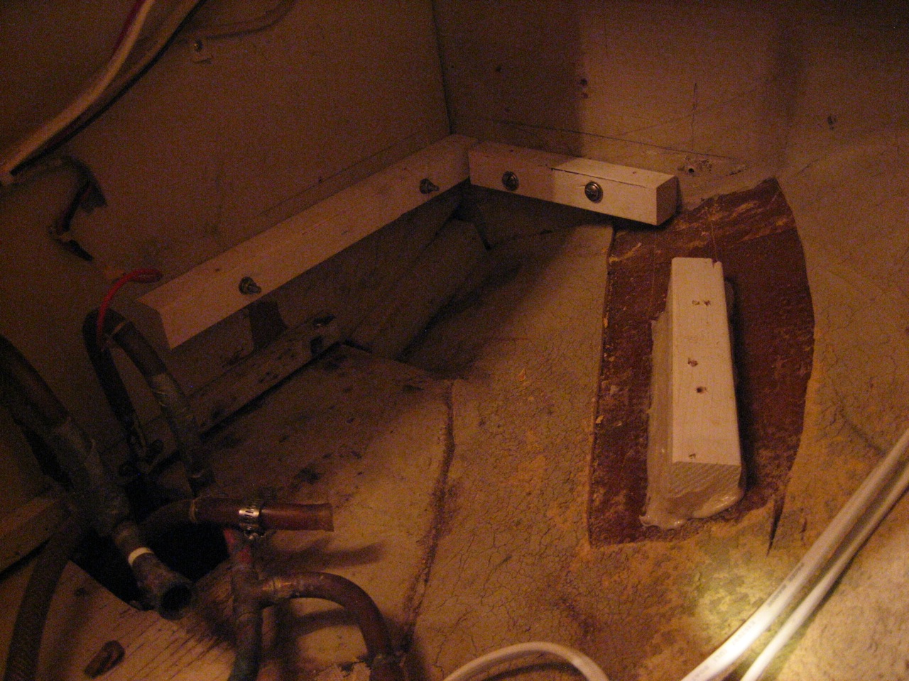
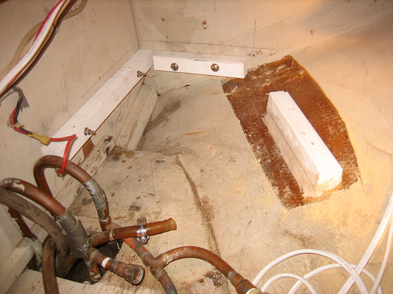
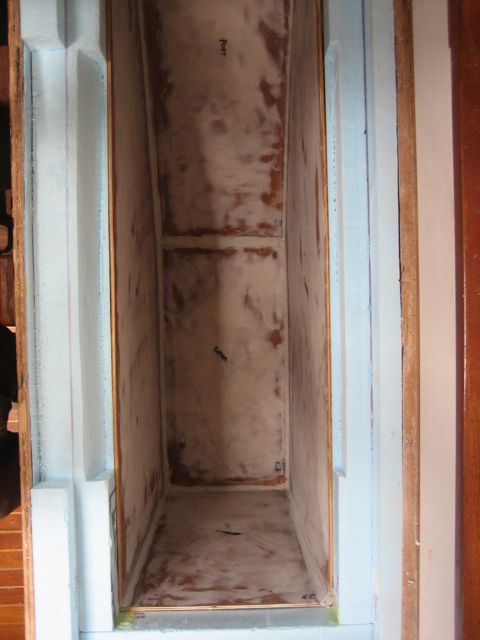
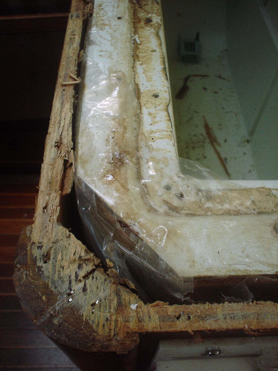
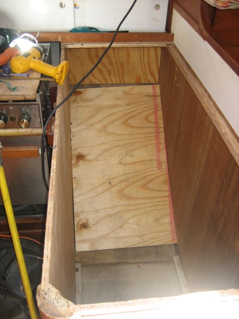
The old propane locker was a fiberglass box mounted in the middle of the stern. It protruded 5″ above the level of the seat, and was suspended in the enormous space of the lazarette, rendering the space unusable and the seat unseatable.
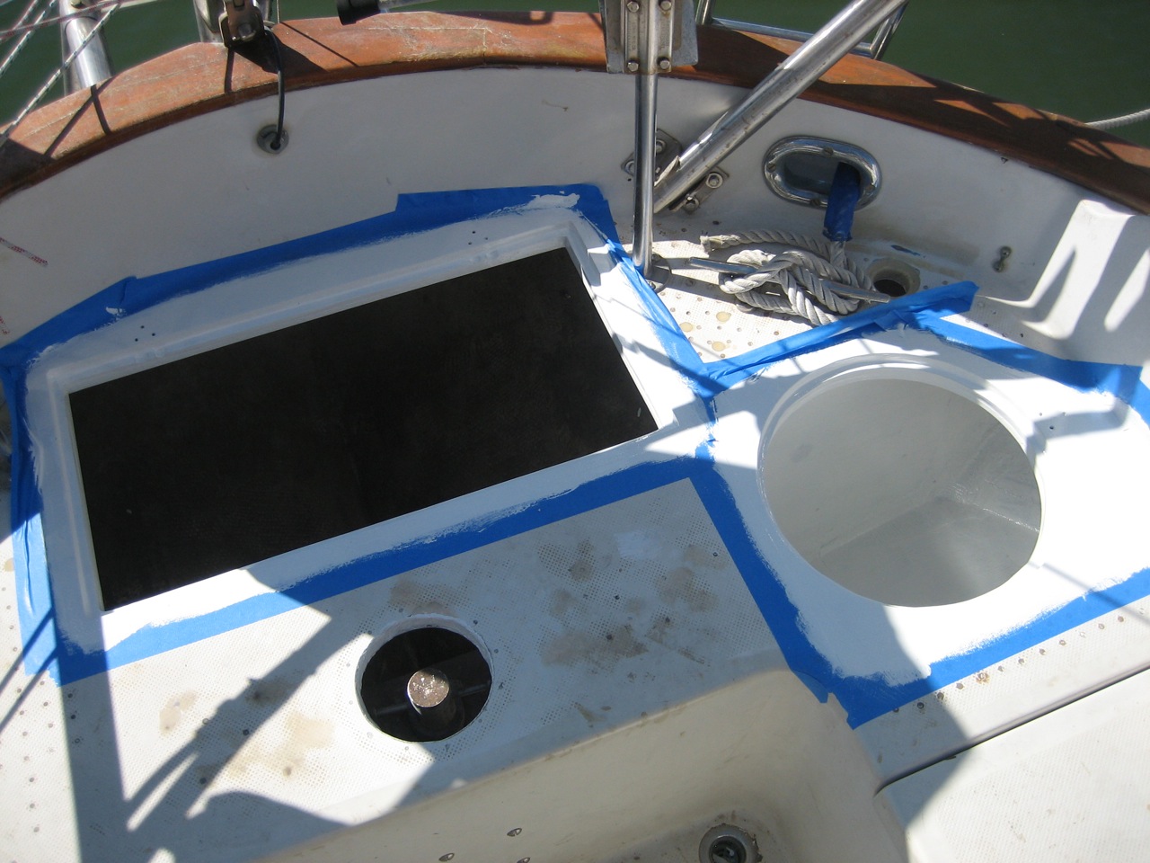
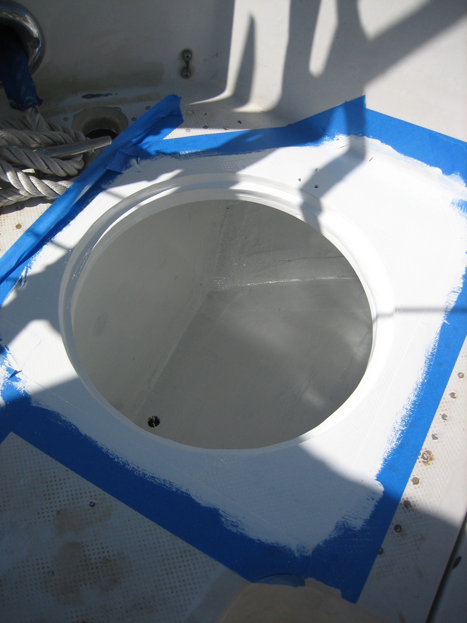
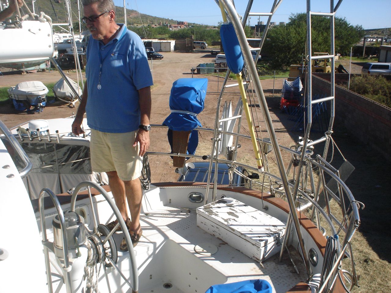
We decided to remove the old propane locker, build a new one tucked into the corner as much as possible, and put flush fitting hatches over the lazarette and propane locker. The job ended up being the biggest so far undertaken on the boat, and isn’t yet finished. Of the many unforeseen hurdles, we discovered that we needed to move and/or reroute all three of the scupper drains on the port side, to accomodate the new propane locker (not to mention close the old propane drain and install a new one). So this job alone required 4 new through-hulls and two new scupper drains on deck.
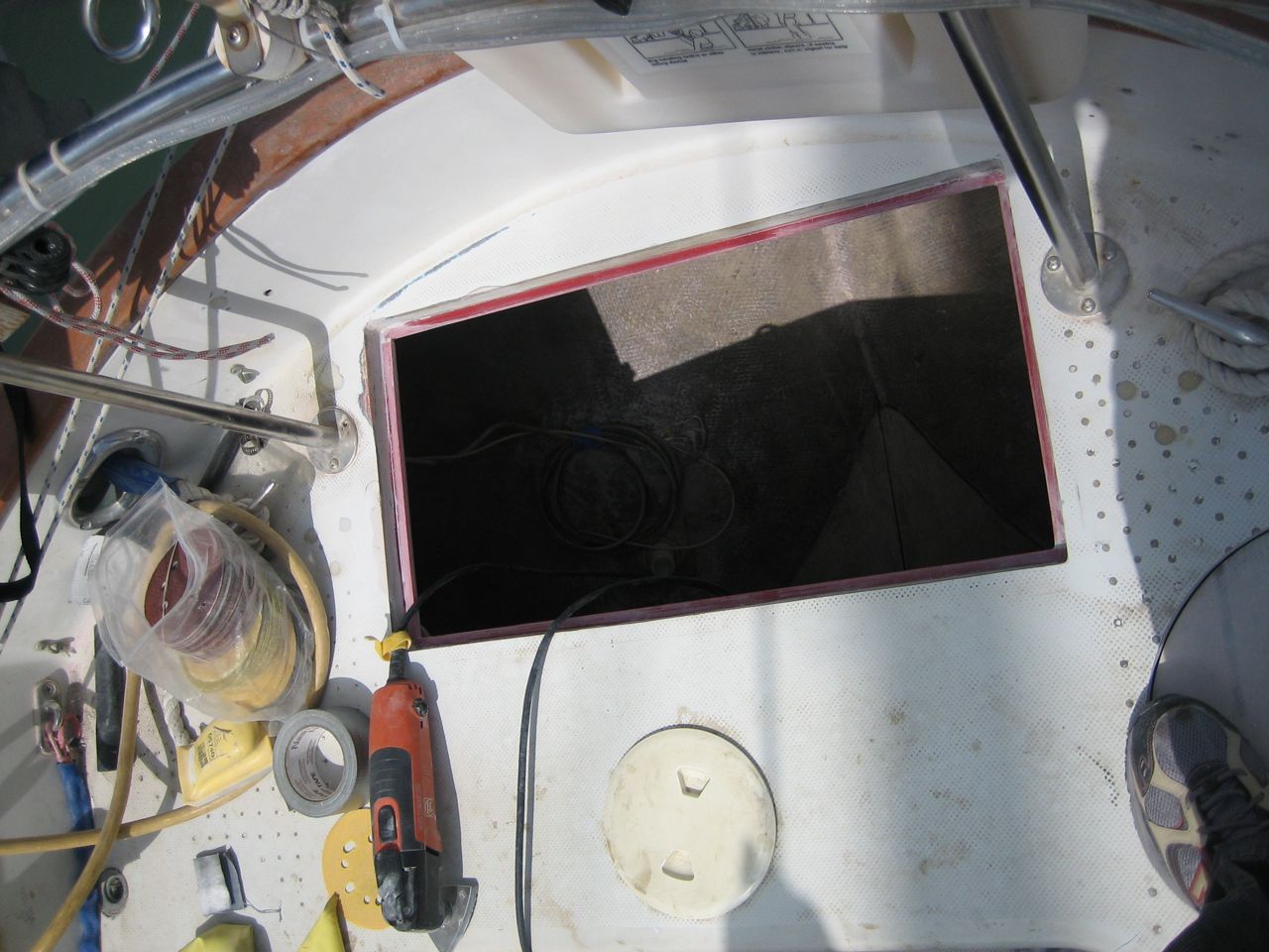
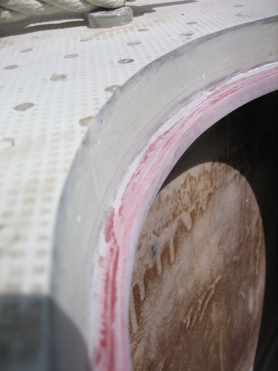
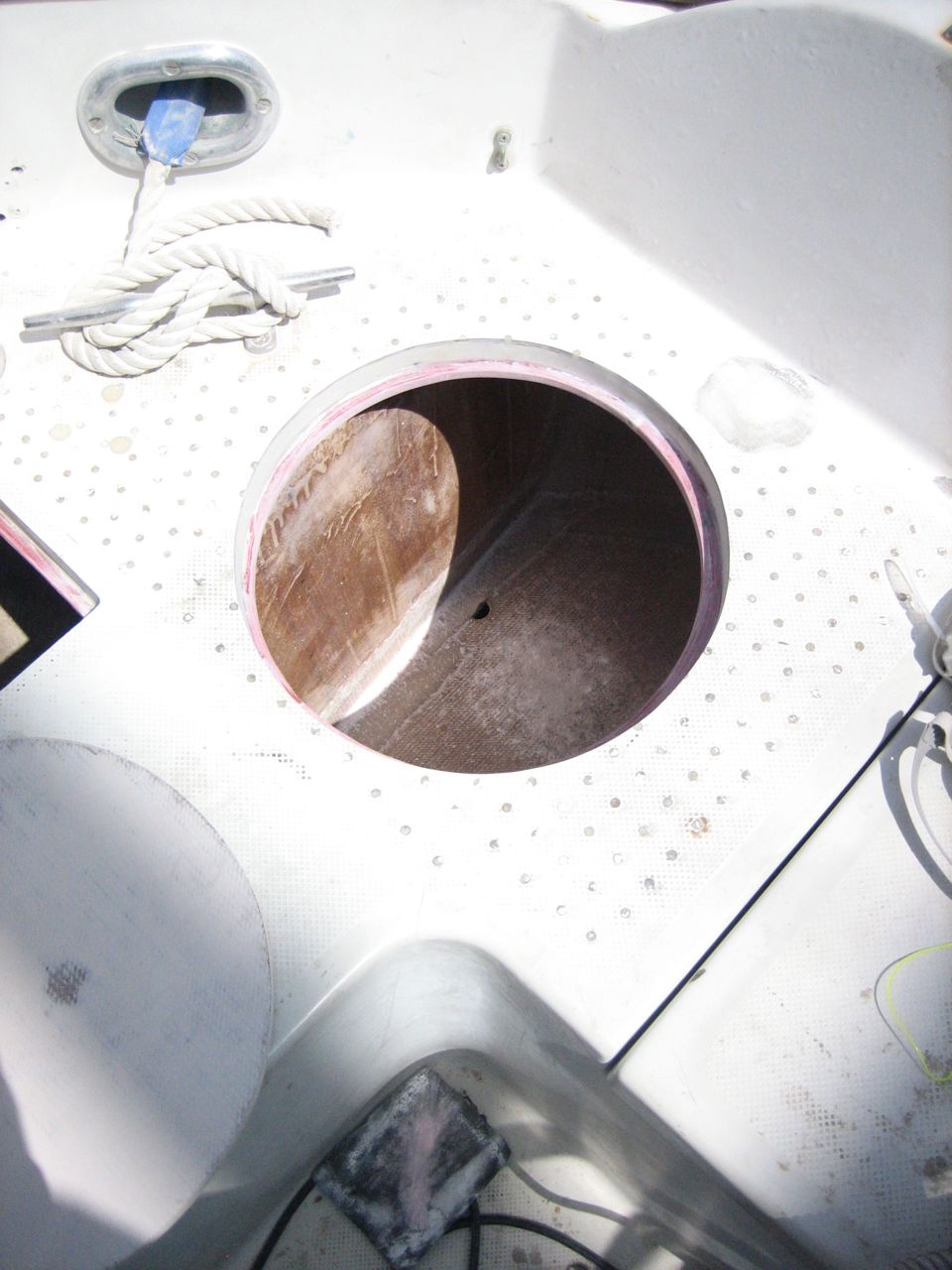
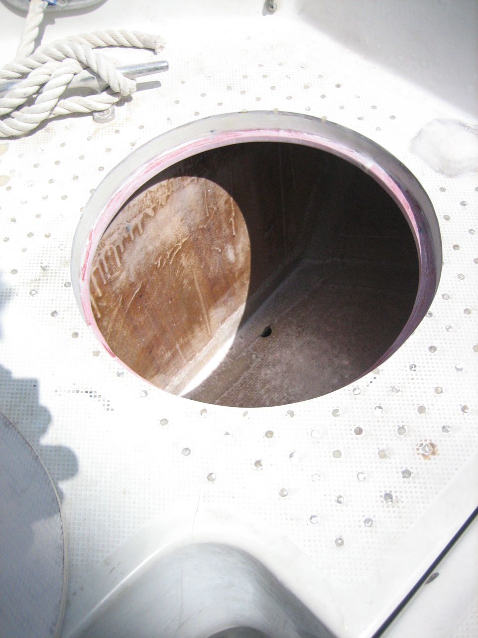
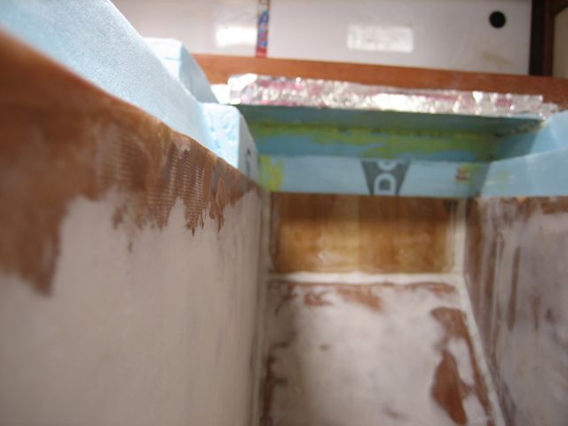
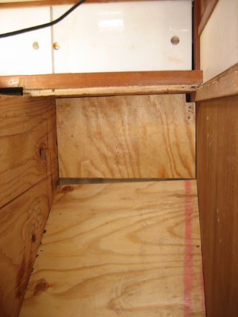
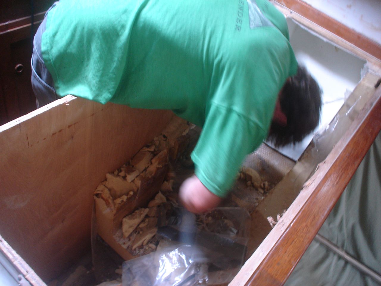
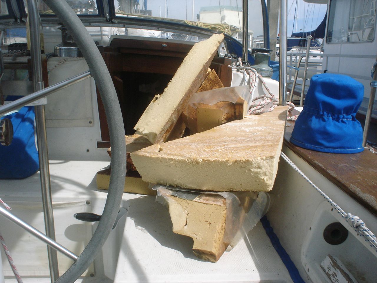
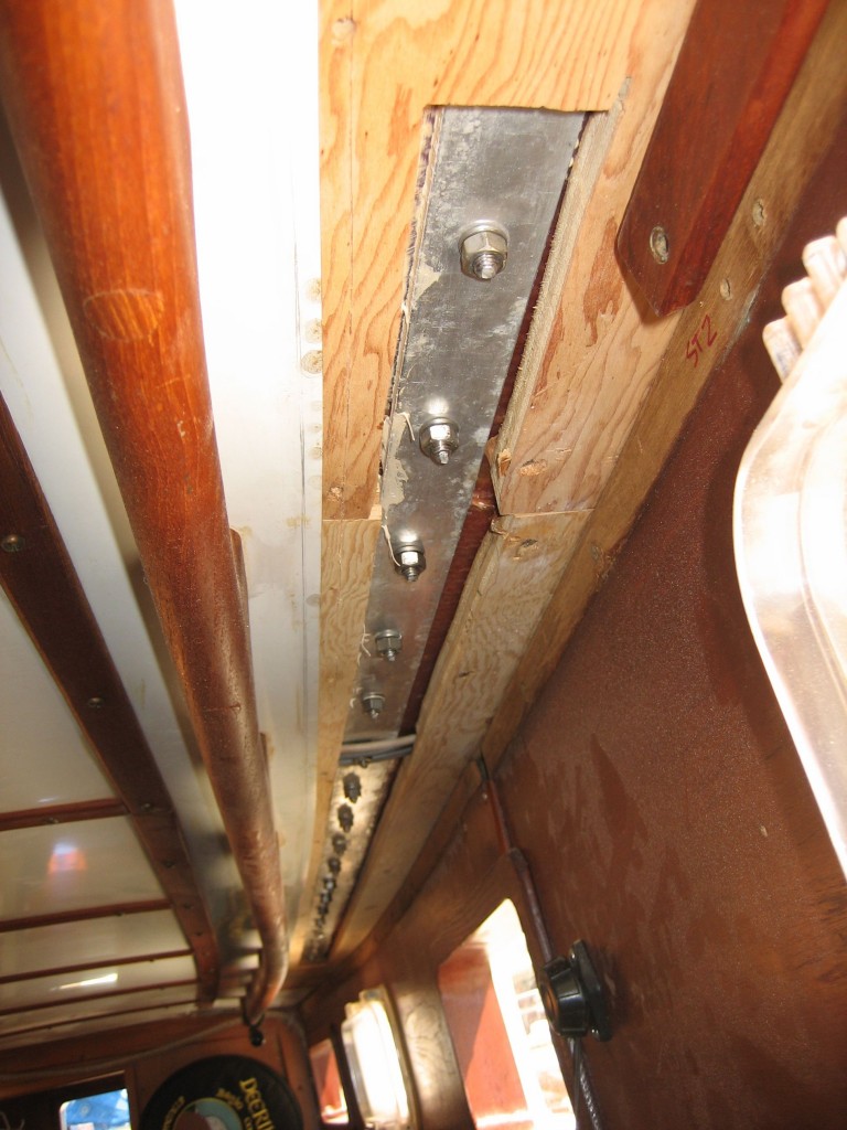
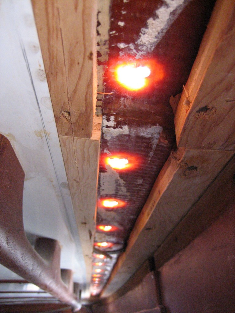
Additionally, the deck just forward of the propane locker, especially around the rudder access hatch, was extensively delaminated (core was perceptibly soggy, damp, and black). Jonny elected to dig out the core from the hatch and rudder post hole (i.e. without removing the top or bottom layer of fiberglass), and ended up removing the core to a distance of close to a foot in the space forward of the new lazarette hatch (there are some pictures of it). Then he carefully measured and cut a few pieces of plywood that he buttered with epoxy and then shoved into the gap. Afterwards there were some gaps left in the core where the plywood didn’t quite reach that I injected with resin, per the usual method (drill holes for the syringe, inject resin until it splooges out all over, let it cure, sand off the puddles of resin, quikfair the remaining divets, sand again).
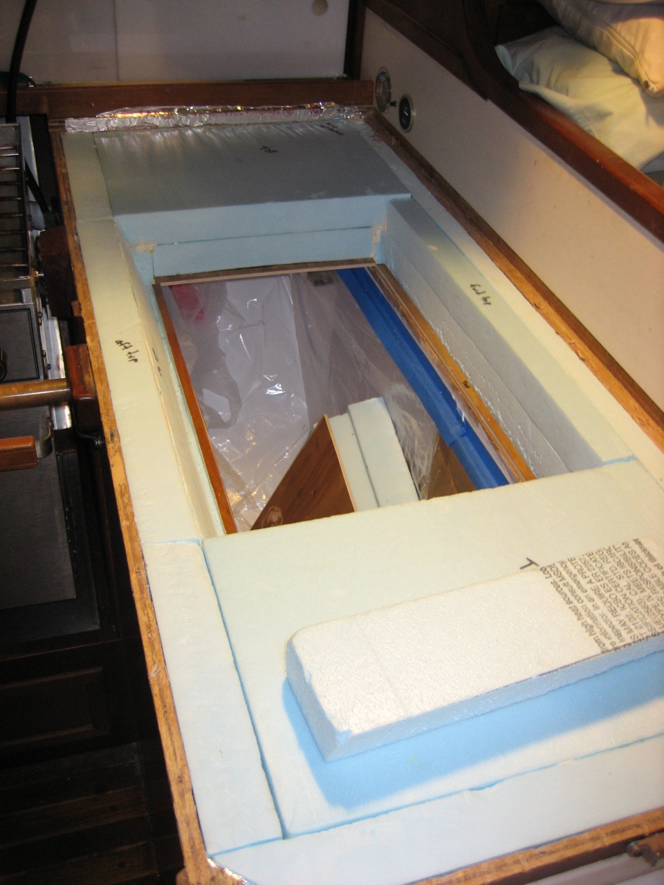
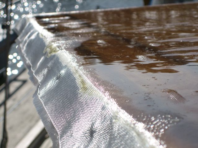
We built the new propane locker and the hatches out of the leftover fiberglass-covered plywood that we had fabricated for the icebox. We used two layers of the plywood for each of the hatches (the plywood was super thin), as well as a couple extra layers of knytex for additional strength.
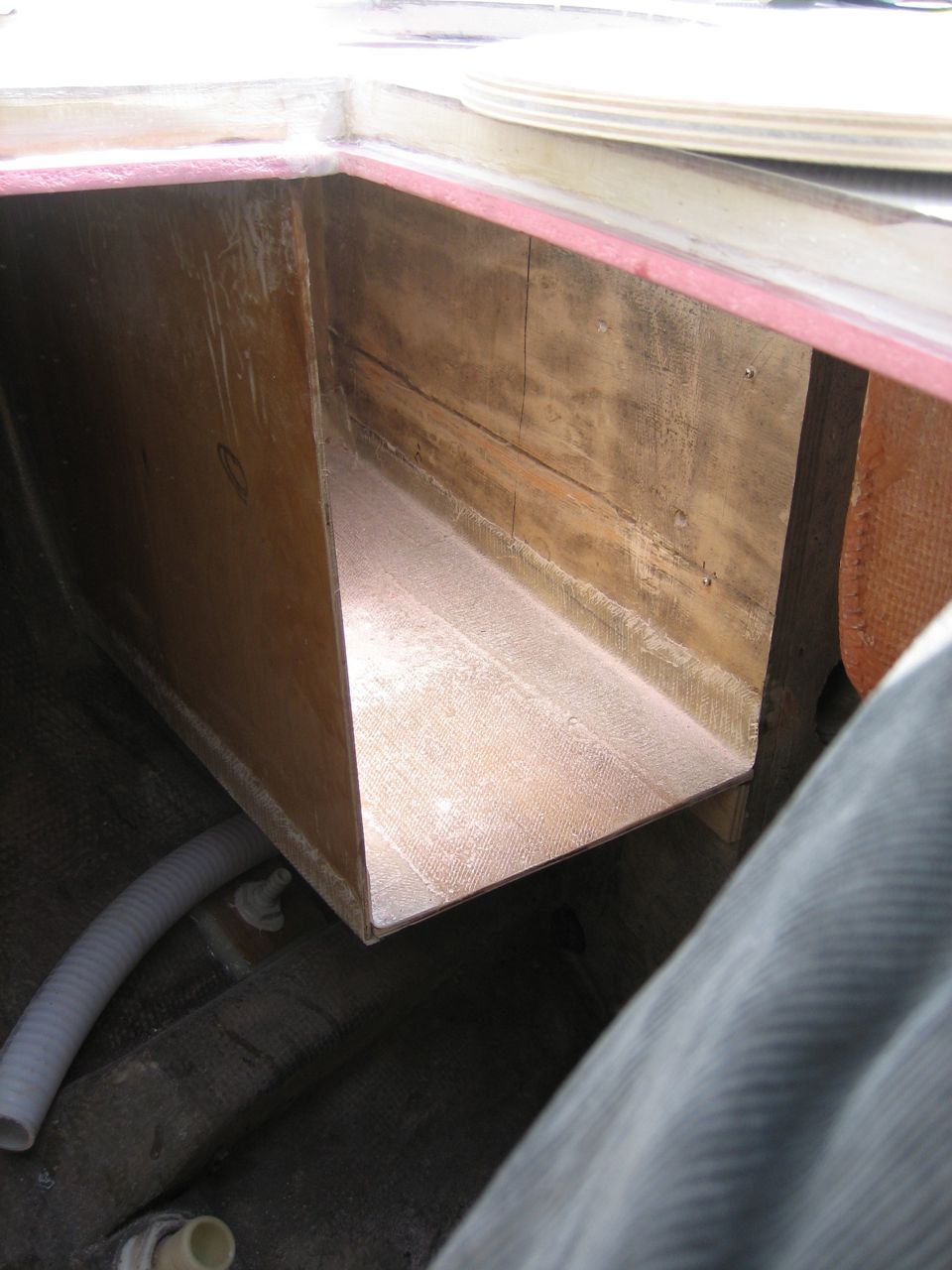
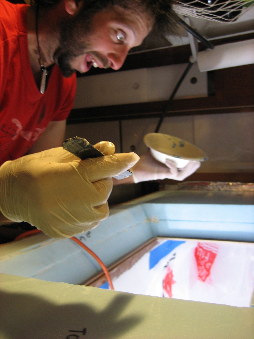
Jonny painstakingly glassed the box in place using strips of knytex–the box was odd shaped to accomodate the curves of the hull and the deck/coaming/toerail ceiling section.
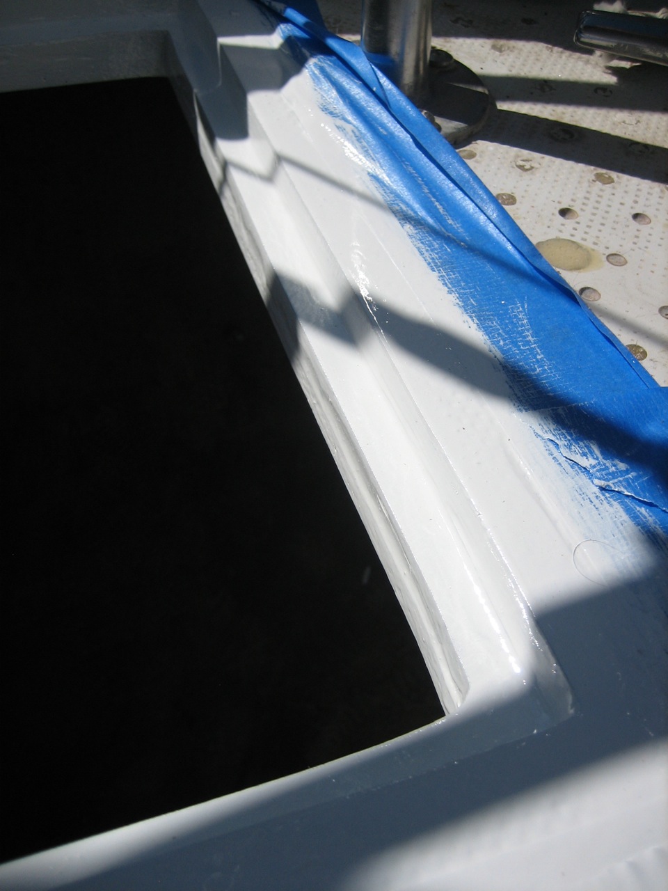
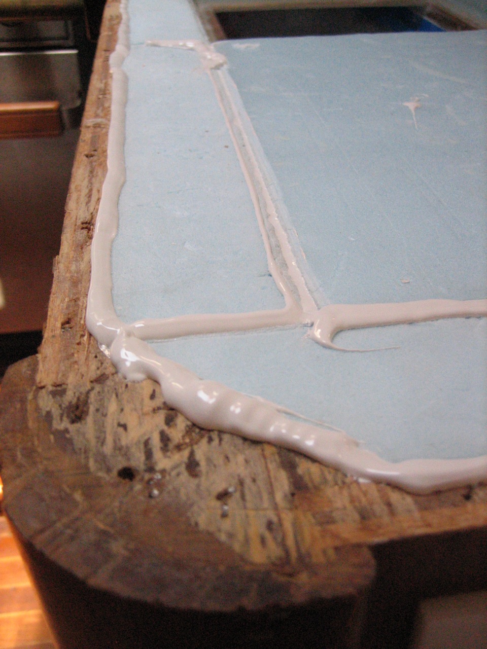
We made the ledges on which the lids will rest out of 3/8″ thick prefab FRP from Mcmaster-carr. The lip is about 1/2″ wide, and the strip that forms the lip extends ~1-1/2″ underneath the deck. The strips are epoxied in place (jonny pre-drilled pilot holes and screwed the strips in place to properly position them while the epoxy cured).
Fairing and sanding the edges of everything was time consuming, as it always is. It consisted of at least two rounds of Quikfairing, preceded by, separated by, and followed by tedious amounts of sanding.
I entirely replumbed the propane lines while we were at it. Per jonny’s insistence we went with a hose to run from the stern to the stove, instead of copper tubing. It was definitely the right choice. It was slightly more expensive, but eliminated extra junctions required at the stove. A hose is required at the stove to accommodate the gimballing, and this way the one 25′ hose runs straight to the back of the stove. I purchased the new style qcc quick connector to be used for attaching to the propane tanks–the previous system required wrenches, and the apparatus that connected to the tank (which included the regulator and the pressure gauge) was awkward and unwieldy. Now a single high pressure line is connected to the active tank, and the regulator, pressure gauge, and other connections are mounted to the propane locker wall. I also added a T-junction and short additional hose with a valve inside the propane locker (in the low pressure side) to be used for a propane grill to be mounted on the rail (which we don’t yet own).
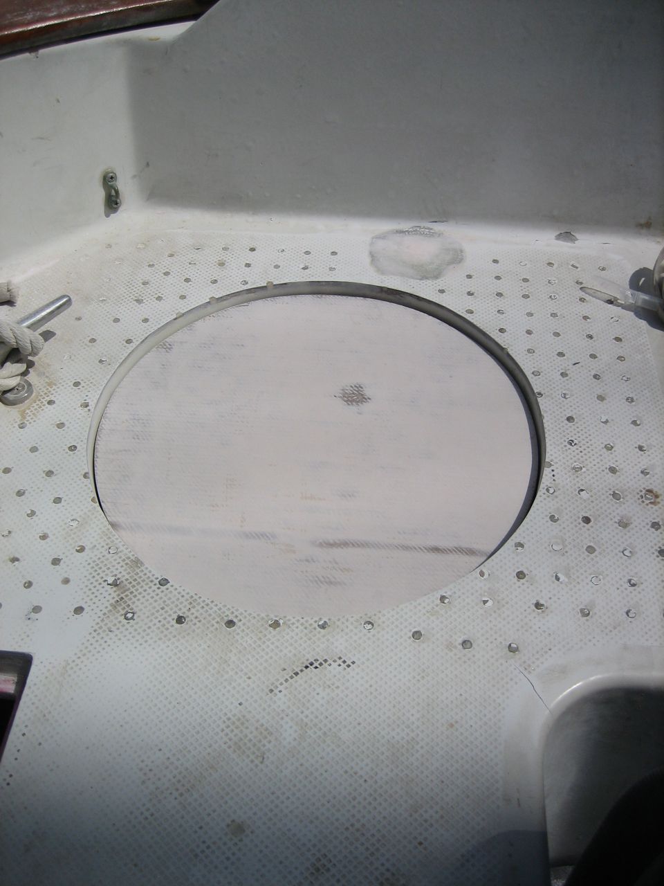
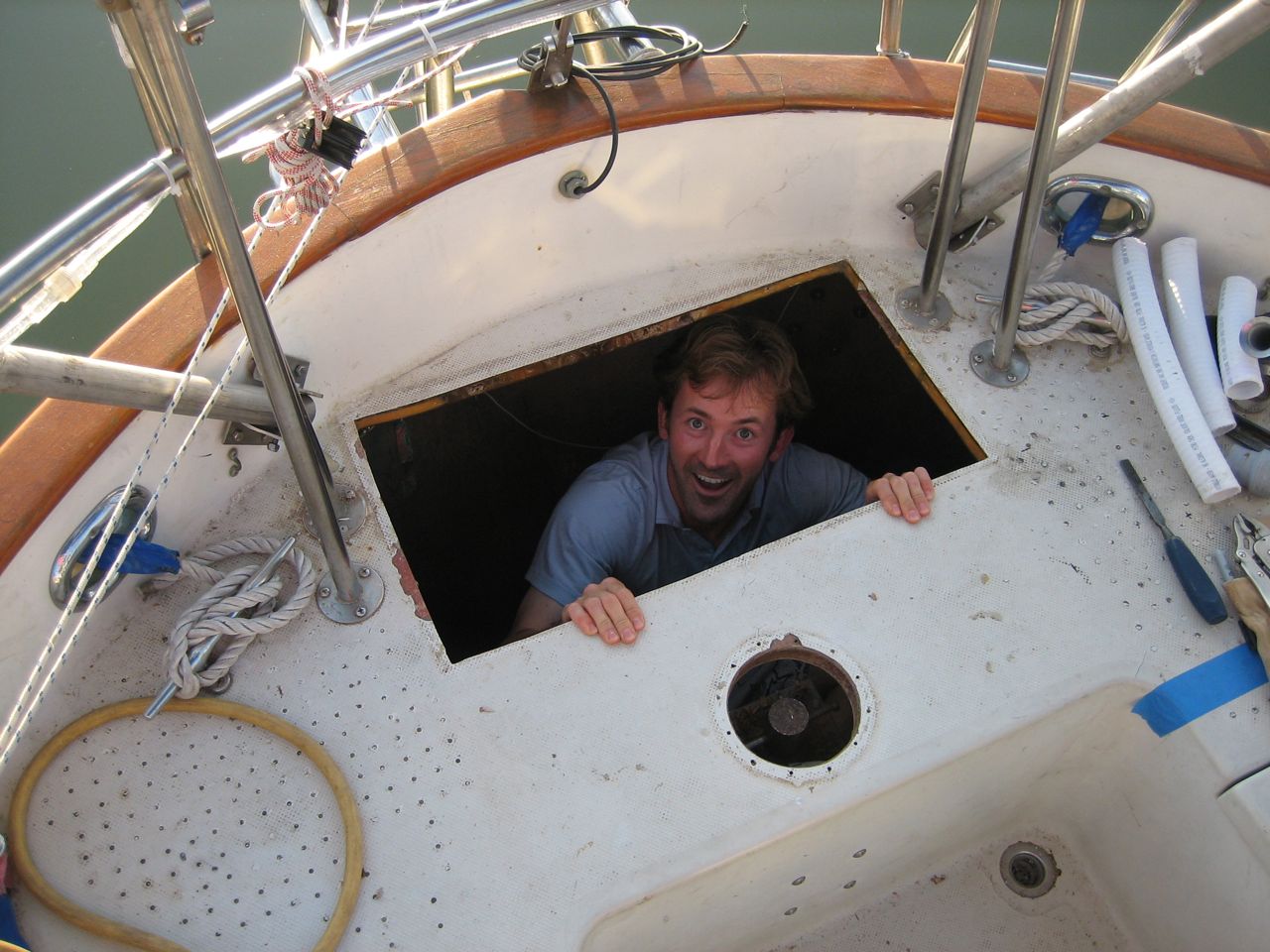
The resulting storage space gained in the stern is astounding. I could lay down and take a nap in the space that we previously had no access to.
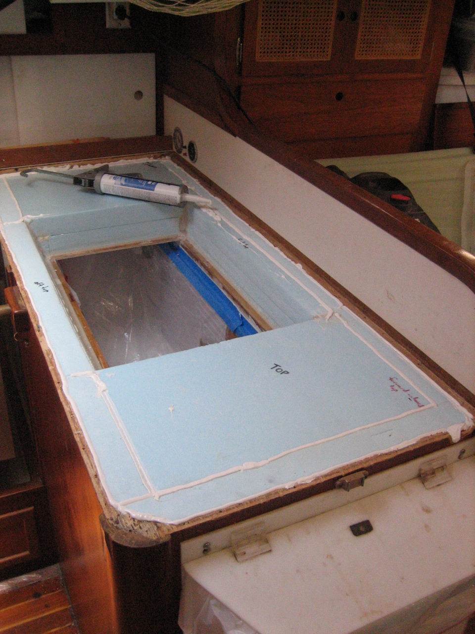
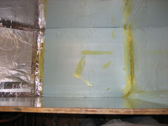
Turns out we left too much of a gap for the gasket, and the lids sink too low, so I created a wall of foil tape around the inside edge, and poured a mixture of slightly thickened epoxy into the gap. After it cured I ground/sanded it down to the right depth for the gasket.
I figured out the hinge situation. Then we painted the lids and the lips with two coats of the Primekote epoxy primer. That’s as far as we’ve got so far. Very close.
I’m not finished posting pictures yet, stay tuned for more.
Built a platform and mounted the compressor, and built/faired the lid for the box. Glued down formica laminate, then painted with two coats of Primekote, sanding in between. Almost finished, just have to put on the two coats of Interlux Perfection, mount a ring pull in the lid, then seal down the hinges and run a bead of caulk around the countertop.
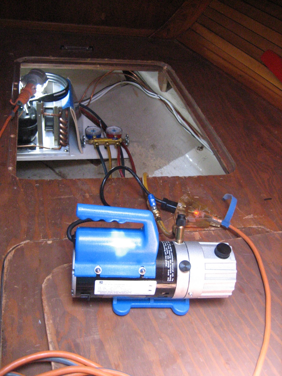
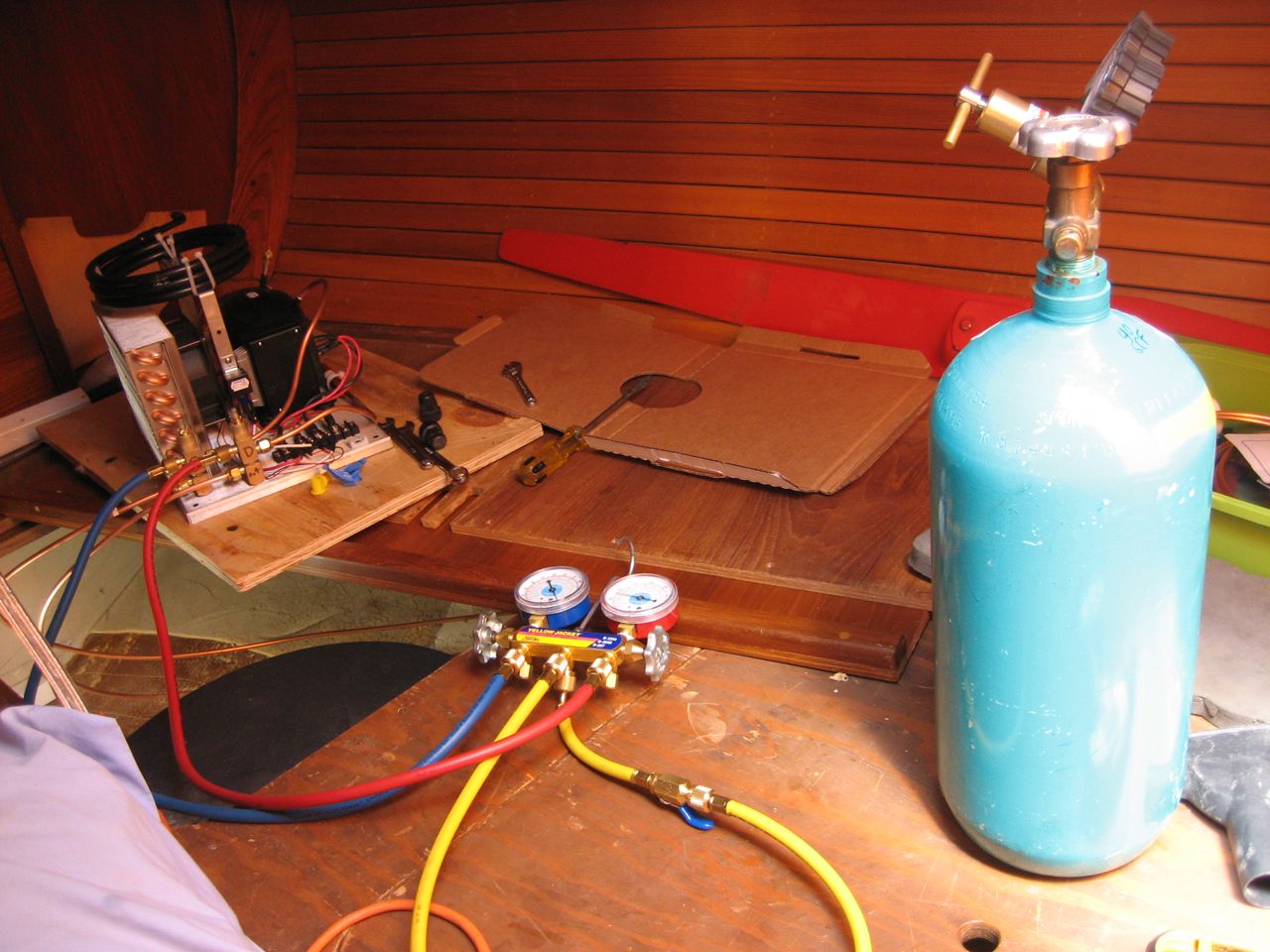
And I pressure tested it using Marcus’s tank of argon and refrigeration gauges (thanks Marcus!), and I have NO LEAKS. It was a very exciting moment for me, I’m not going to lie, I was really proud.
Next step: fabricate mounting platform for it, wire it up, then vacuum down the system and charge it up.
I’m working long days (paid work I mean) for a few months though, so I don’t have much time to work on boat stuff.
Changing the oil on the engine was unnacceptably difficult–you had to insert a small diameter tubing down into the dipstick tube (on the hard to reach side of the engine) and then pump it all out by hand. Because the tubing had to be so thin to fit down the dipstick tube, it pumped super slow and hard, and was a tedious, laborious job.
You don’t want it to be so hard to change the oil, or you won’t ever do it when you should.
My dad bought me an oil transfer pump for christmas, and we plumbed it into the drain plug fitting in the bottom of the oil pan. It was challenging to piece together all the fittings in the tight space under the oil pan.
The first time we used it confirmed all of our efforts–you pump out the old oil, then stick the end of the hose in the new oil and pump the new oil right back in the same way. Simple, clean, quick, easy.
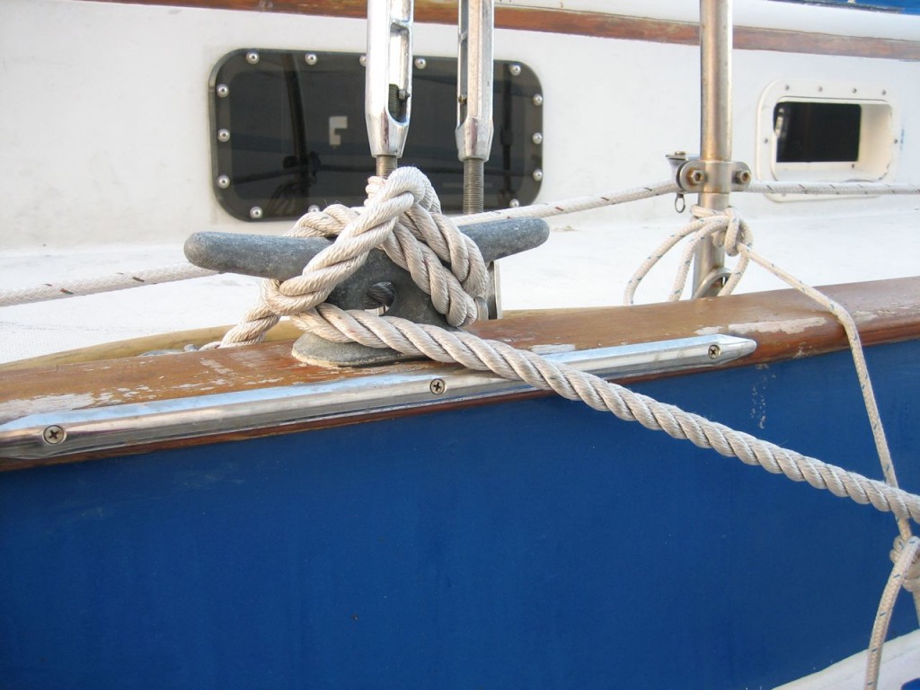
In the previous setup, lines were tied to a shackle mounted on the deck and led through a fairlead on the toerail. We wanted a proper cleat amidships, so we mounted one on each side directly on top of the toerail. It has greatly improved our handling of the docklines.
To recap: initially I was going to buy an Adler-Barbour Cold Machine, hook everything up, and be done with it. After talking to Marcus, I decided to order all the parts from Rparts.com and build my own.
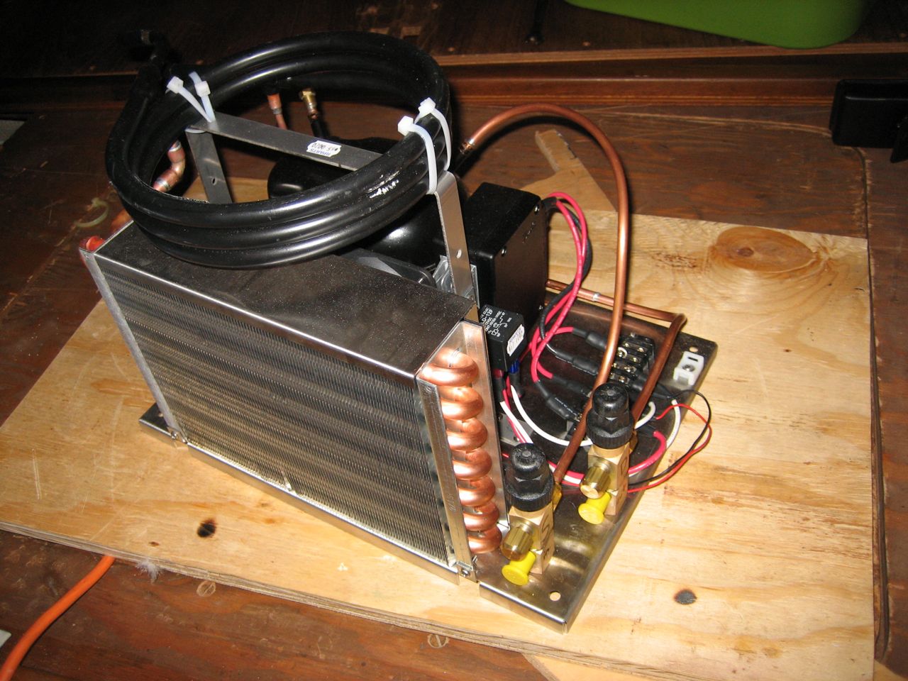
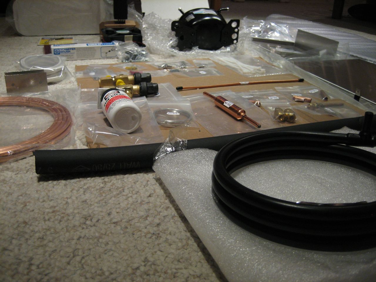
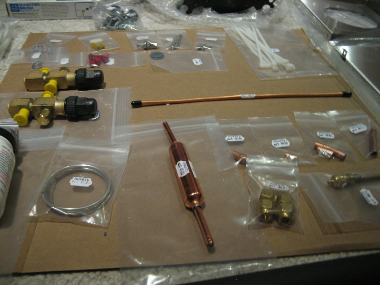
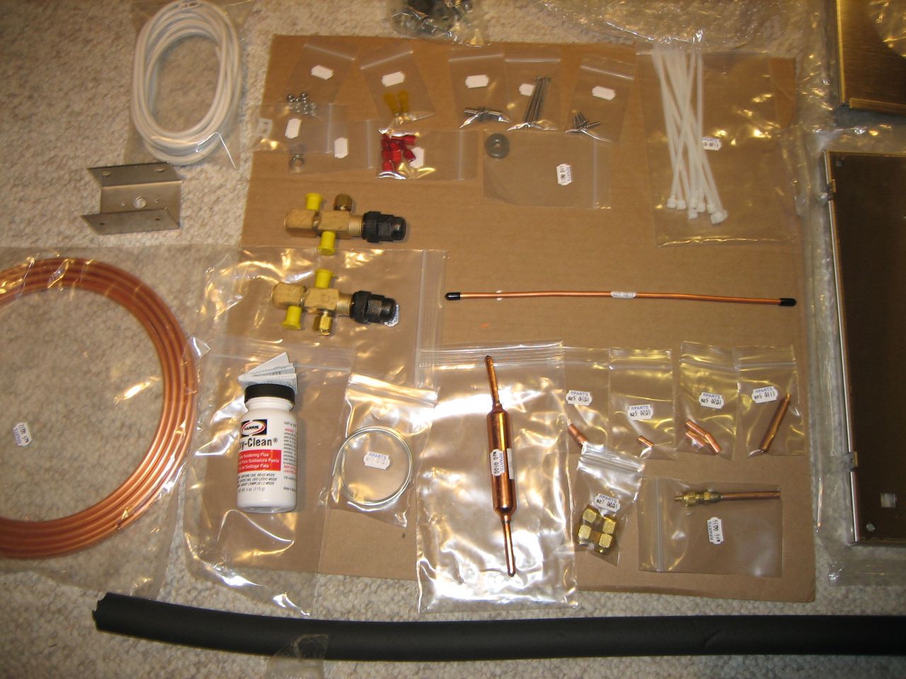
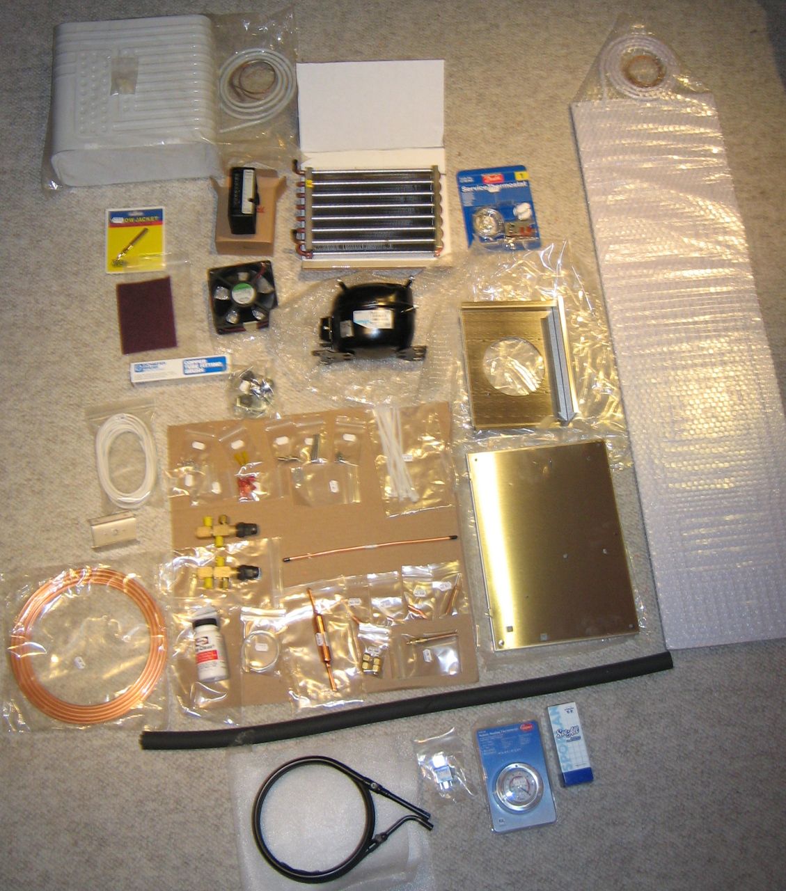
I ordered the 1M kit, which uses an air-cooled condenser and the Danfoss BD50 compressor, and comes with a small evaporator box. Extra things I bought beyond what comes with the 1M kit: the small evaporator box is both too small capacity-wise and doesn’t fit well in our icebox, so I also purchased a large flat-plate evaporator, unbent, and we’re going to bend it ourselves (they wouldn’t switch out the small box for a large flat plate, but they gave me a 20% discount on the extra one, so I got it for $80). I wanted to have both air- and water-cooled condensers, so I bought a water-cooled condenser which I am going to figure out how to mount and plumb in somewhere. I bought a 40 amp relay to use for powering the water circulation pump, and an analog thermometer to mount outside the icebox.
It all arrived today. It felt sort of like christmas, unpacking the boxes and discovering all of the parts. I took photos of all the stuff spread out on the floor. Below the black foam tubing are the extra parts beyond the 1M kit (and the white flat plate evaporator on the right).
There are a whole lot of parts for me to put together! And I won’t be able to start on it for at least another two weeks.
damn it we just can’t seem to catch a break when it comes to the engine overheating. We went out for a fireworks show and on the way back we started overheating. Fortunately, idling down to 3 knots boatspeed kept the temp under 200 so we were able to get home.
Clearly, we have reduced cooling capacity. A complete failure of the cooling system would be much easier to fix–it would be far easier to find the problem. This reduced capacity could be cause by any number of things.
I took some video of the water coming out of the exhaust, so I could hopefully get someone to tell me whether it looks satisfactory or not. Of course, when we’re actually underway this probably changes (I know at times the dribble coming from the anti-siphon vent disappears).
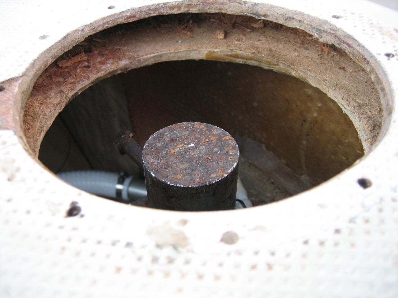
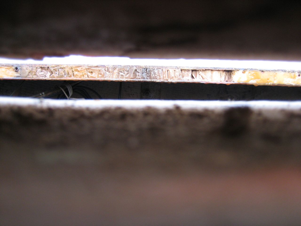
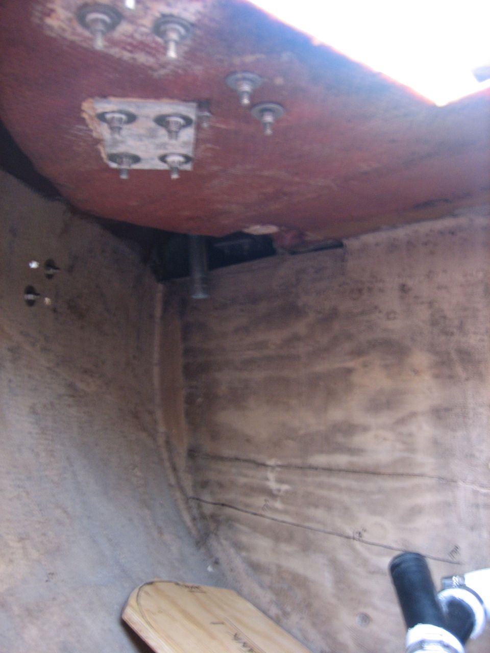
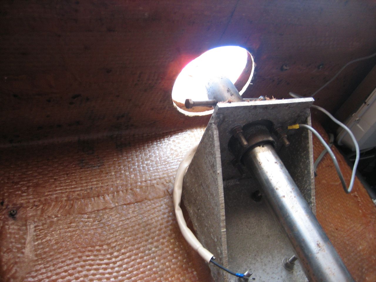
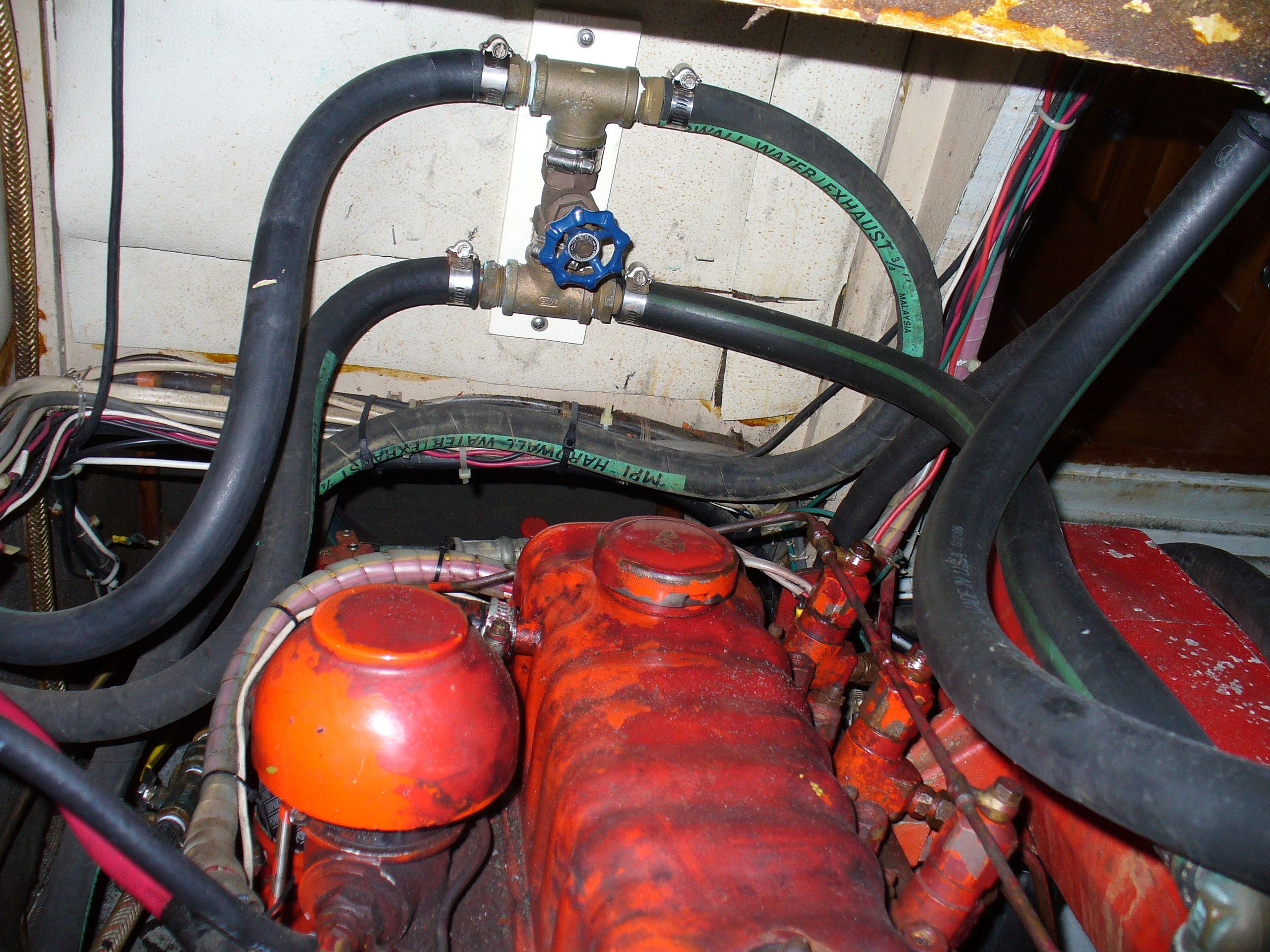
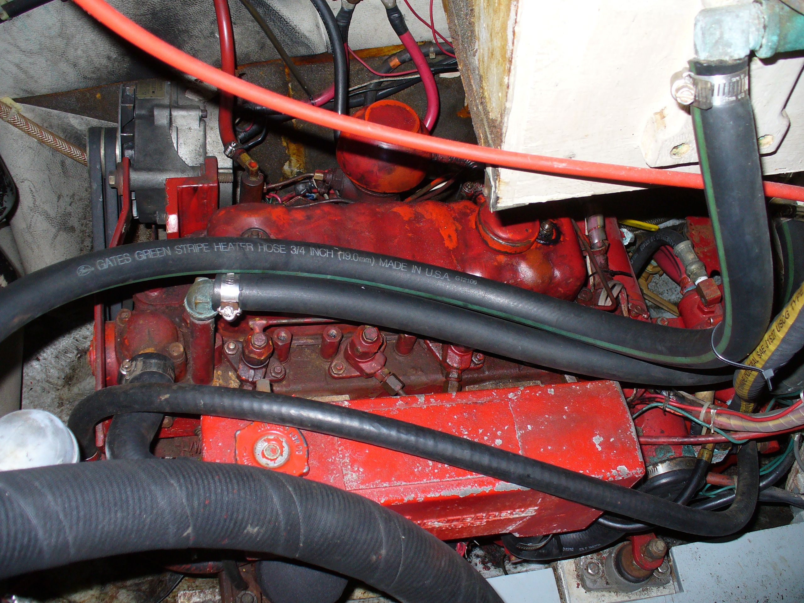
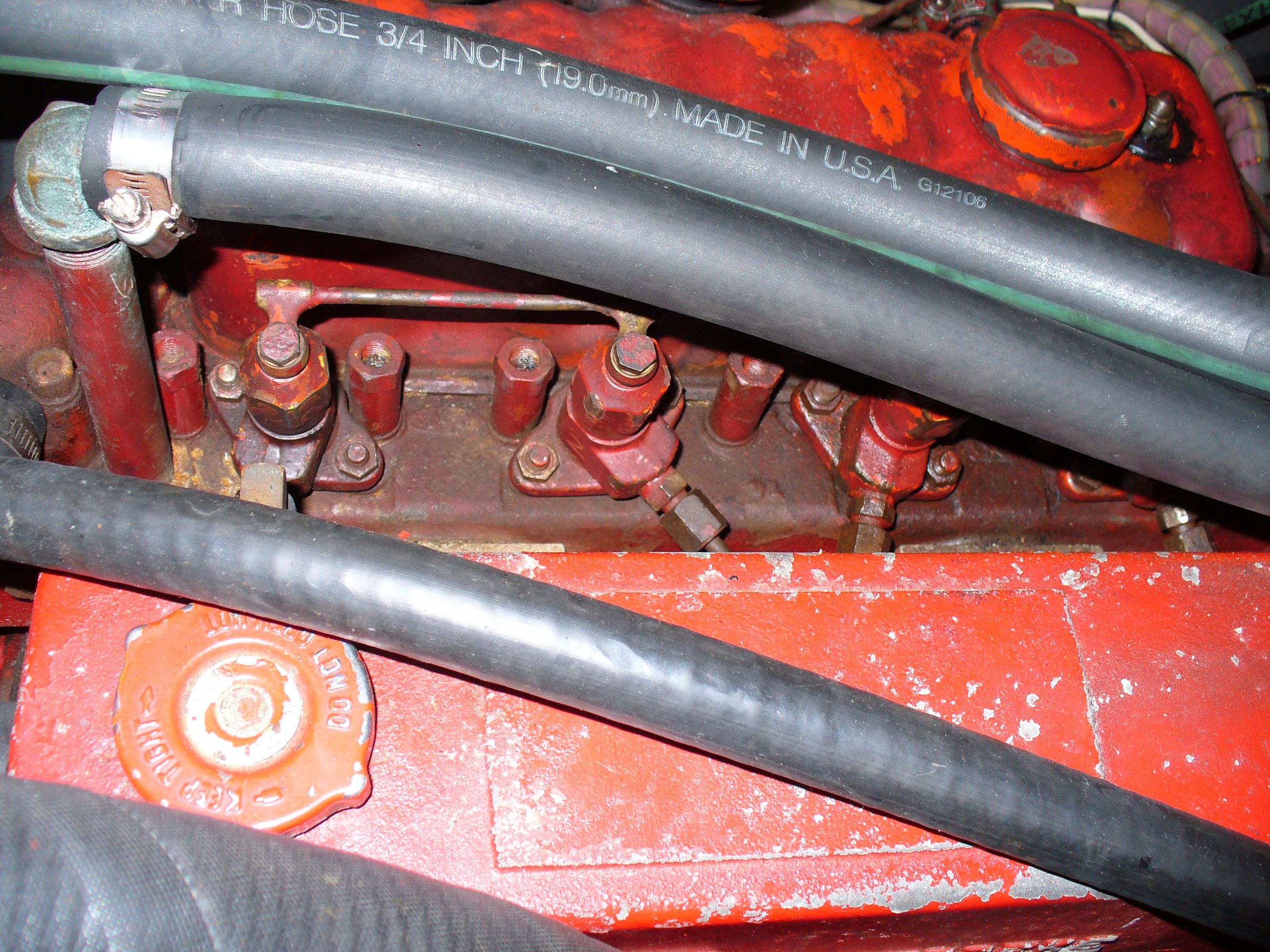
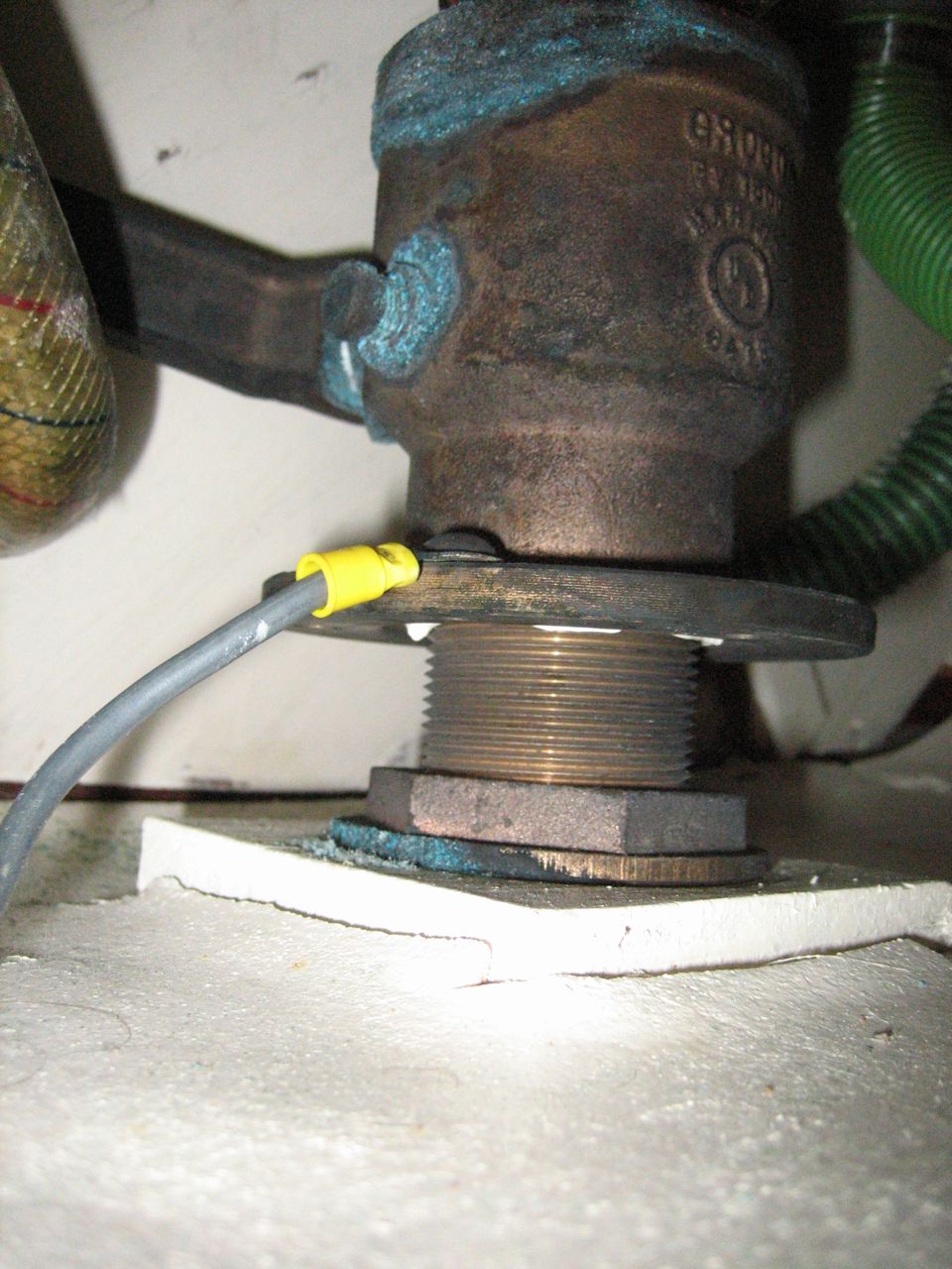
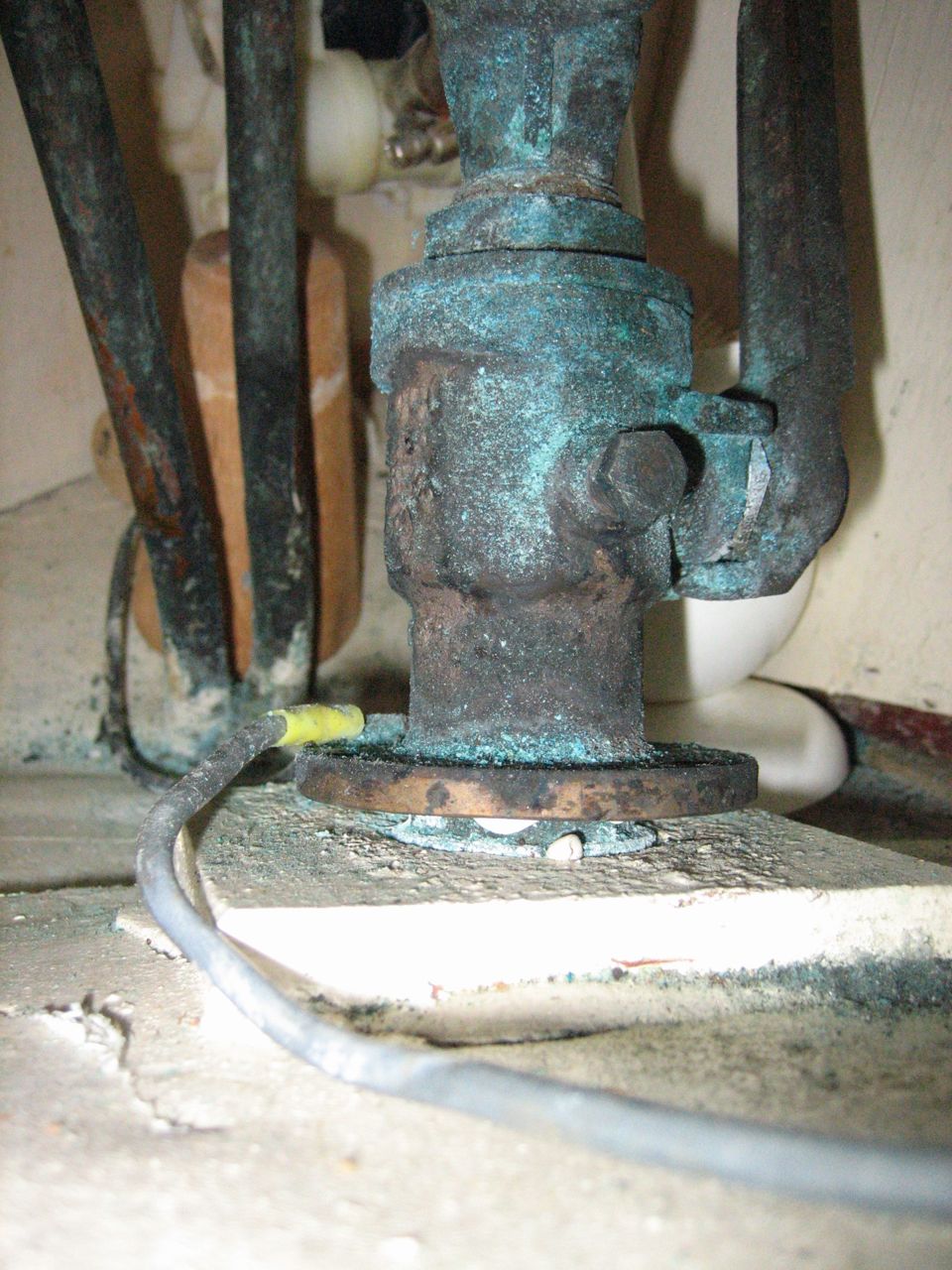
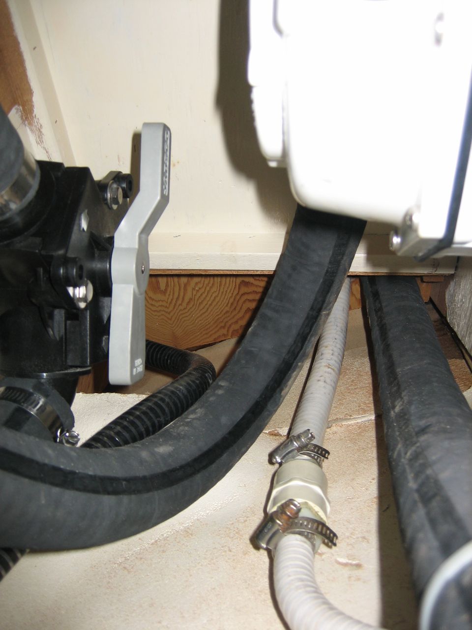
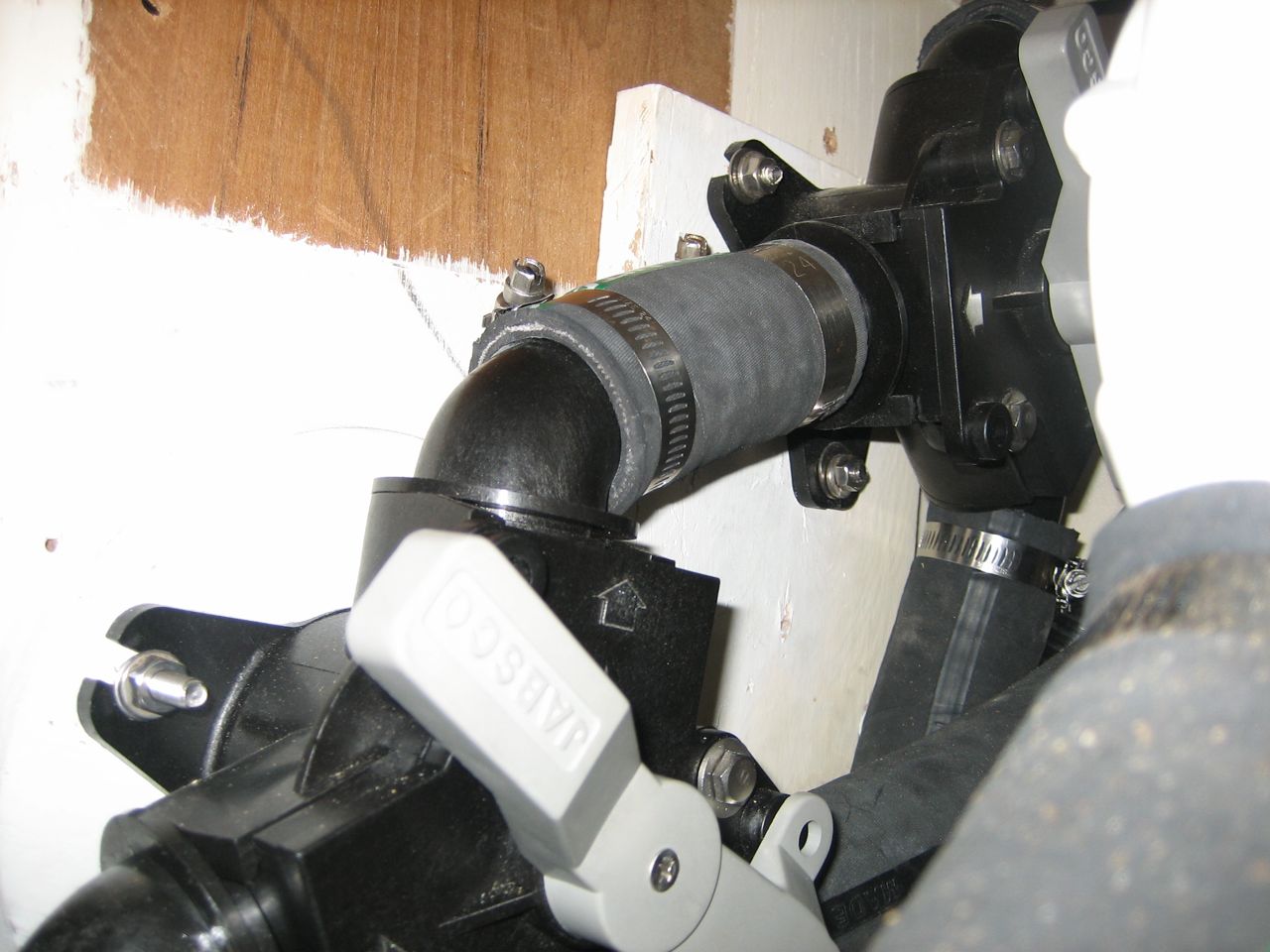
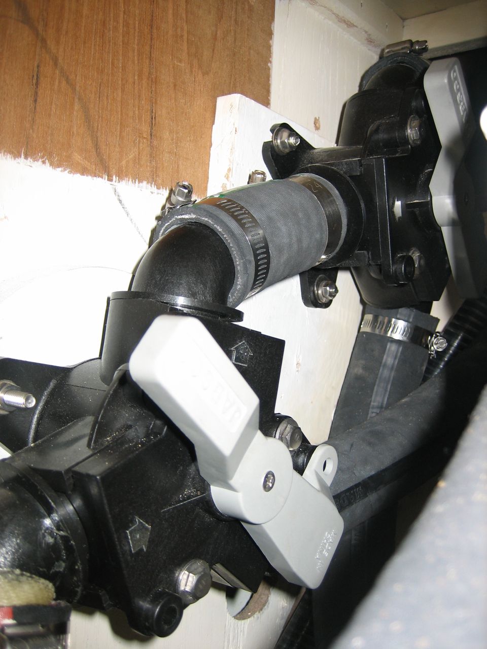
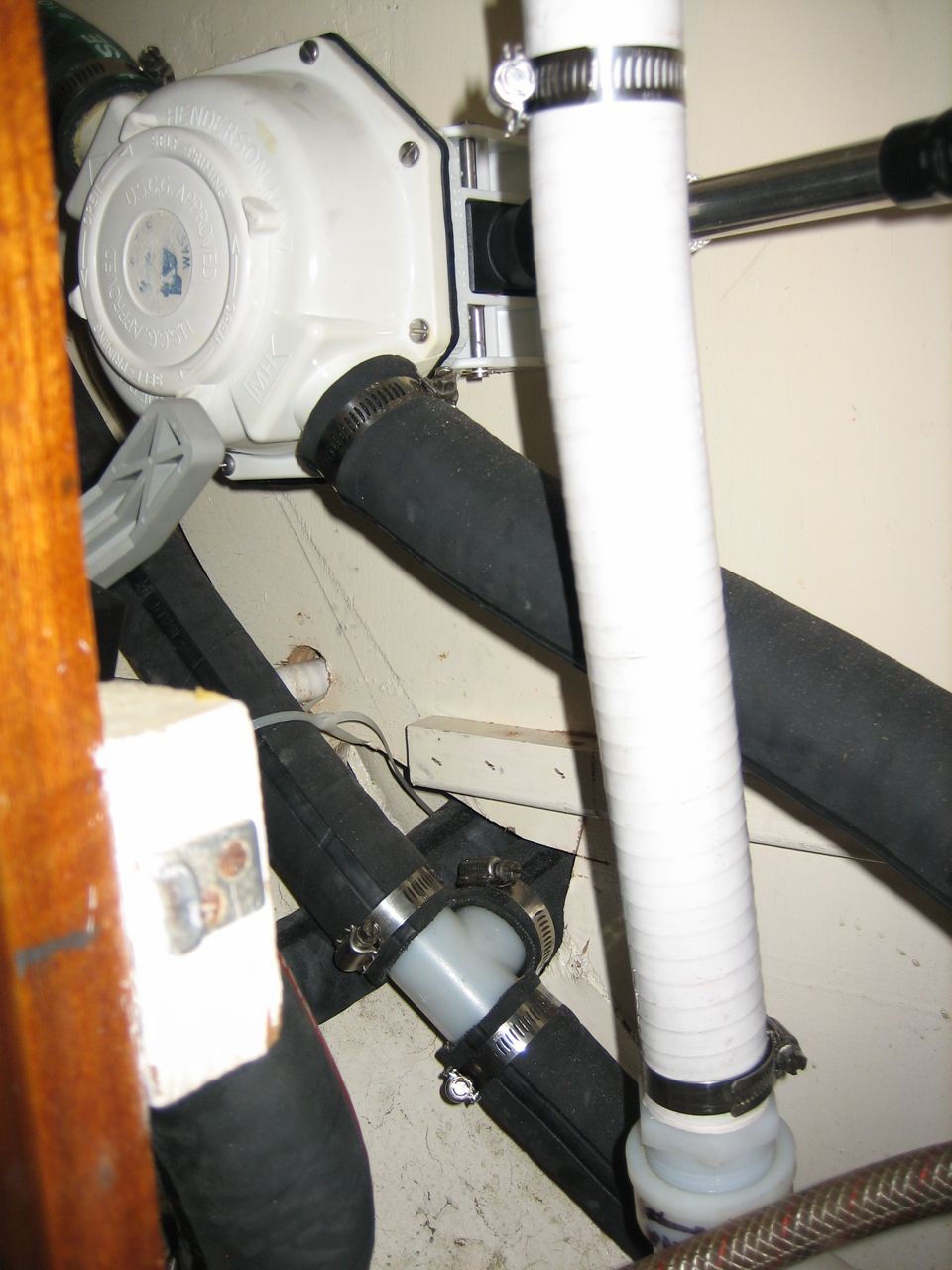
It could be something to do with our water heater plumbing. I’ve heard terms like “airlock”, and heard plenty of stuff about needing to bleed from the highest point, but I don’t understand what is up with our setup. Here are some shots for people to look at:
1. prop fouled–try cleaning prop 2. strainer outside boat clogged; remove hose from sea strainer and see how fast the ocean comes into the boat (should be quite alarmingly fast) 3. sea strainer could be clogged beneath the basket even though it looks clear–take it off and run something through to check 4. the gasket on the cap of the sea strainer may not be air tight–we might be sucking in air as well as water 5. oil cooler could be partially plugged 6. even partial blockage in heat exchanger could cause the problem 7. cam in seawater pump may be worn out (difficult to tell by looking it it with amateur eye) 8. impeller might be sheered between hub and blades, even though it looks perfectly fine 9. gauge might not be properly calibrated; get an infrared thermometer to check 10. fragments may be lodged in hoses or exit from raw water pump, or heat exchangers; remove hoses and sight down them to double check, try flushing with garden hose 11. clamps on raw water side might be loose; anything allowing air to be sucked in will mess up the cooling 12. back plate of raw water pump may be worn out–check to see if there is noticeable wear or grooves where the impeller has worn into the back plate 13. cooling system may have an air-lock, especially with the hot water heater installation; try bleeding air from petcock on top of heat exchanger (is that high enough to take care of it?)
things we already checked -thermostat could be the wrong temp, or not working properly -heat exchanger, oil cooler, tranny oil cooler could be scaled up
The next thing to do is run down this list I guess. Really excited about that.
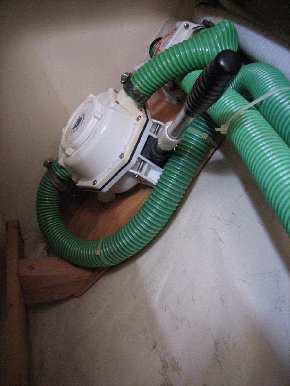
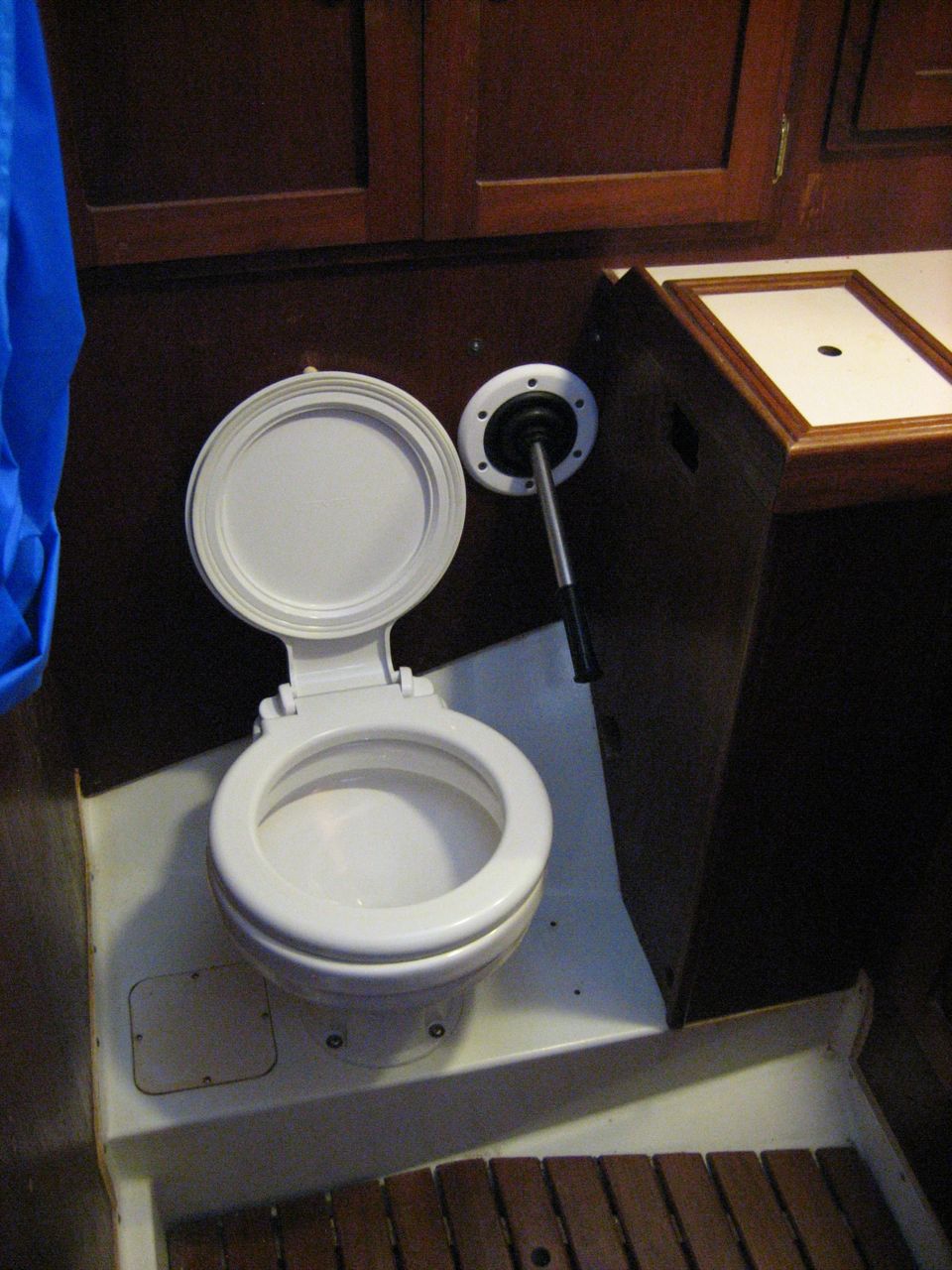
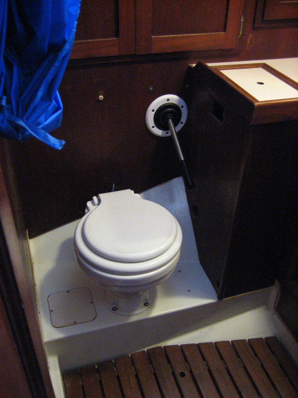
I actually did this half a year ago, but I didn’t want to post without pictures of the head, and the whole room has been so dirty and full of crap that it took me a long time to finally get around to cleaning it up to take some pictures.
I’m particularly proud of this job–I designed the whole system myself and I think it worked out really well. Way back in mexico we tossed out the old head and all the associated plumbing, keeping only the holding tank installed in the v-berth.
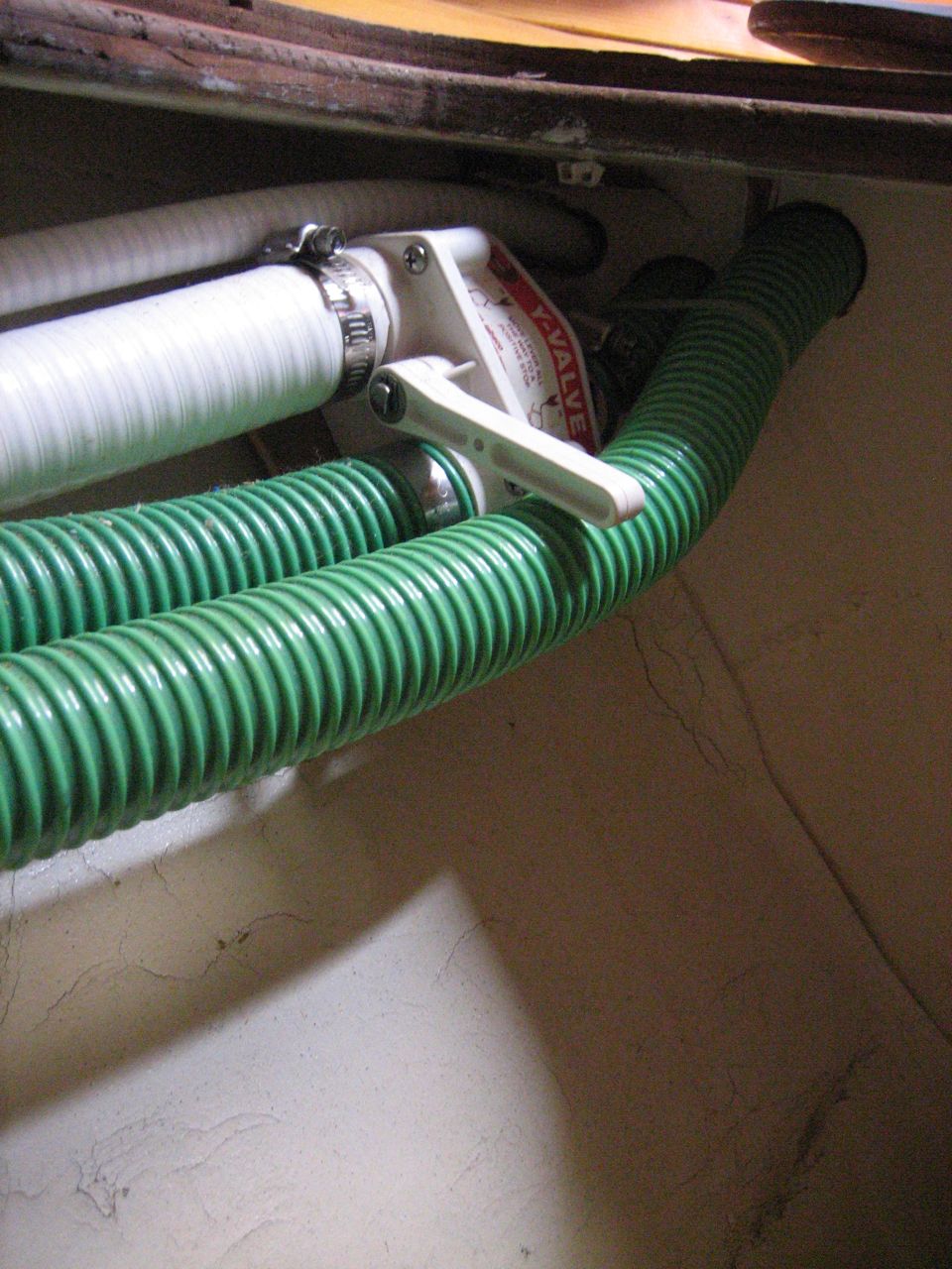
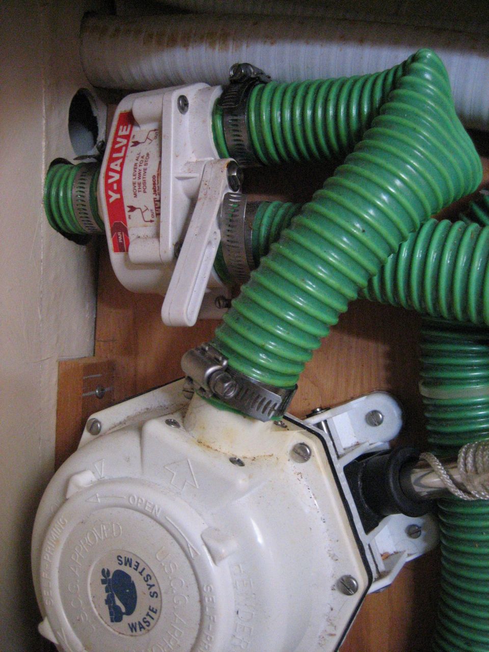
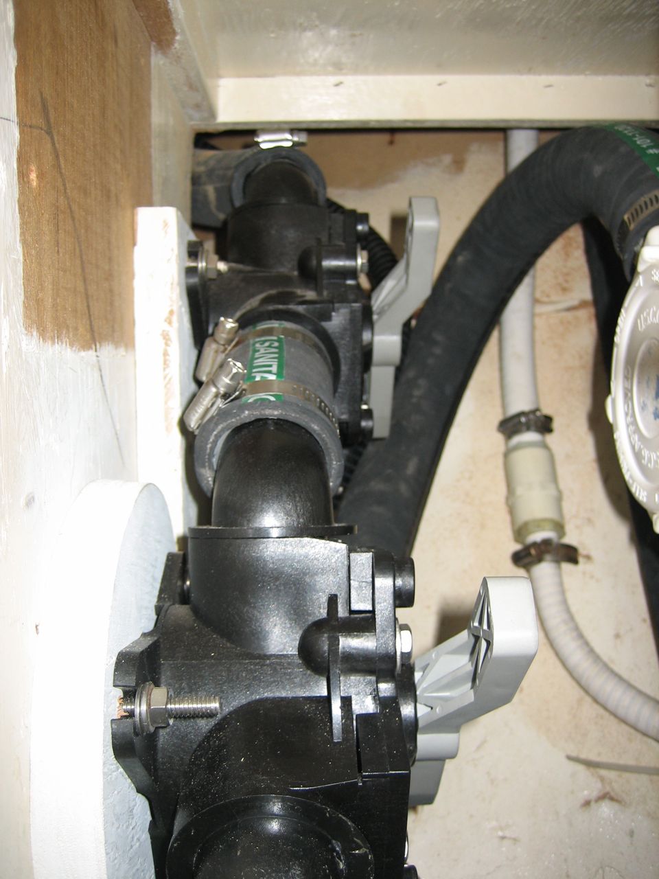
I chose the Lavac for our new head. The Lavac works differently from the standard marine heads. Typically, heads use a somewhat complicated double action pump that is the weak point of the system. The Lavac uses a regular Henderson Mark IV diaghragm pump. To operate it, you close the lid and start pumping. The lid seals to the toilet bowl, and as you pump out the shit, clean seawater is sucked in. Then you can lift the lid and pump a few more strokes to completely empty the bowl.
I wanted damn good hose for this shitty task, so that hopefully it will take a really long time before it starts smelling bad. I chose the Trident Sanitation hose #101. It’s expensive but we got a great deal on it, and I really really don’t want shit smell to permeate our boat.
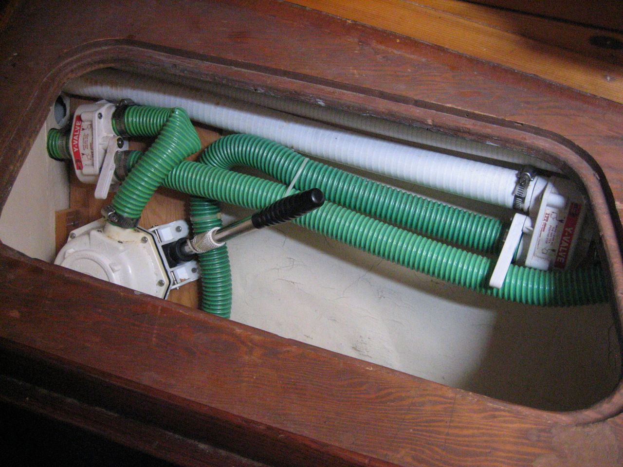
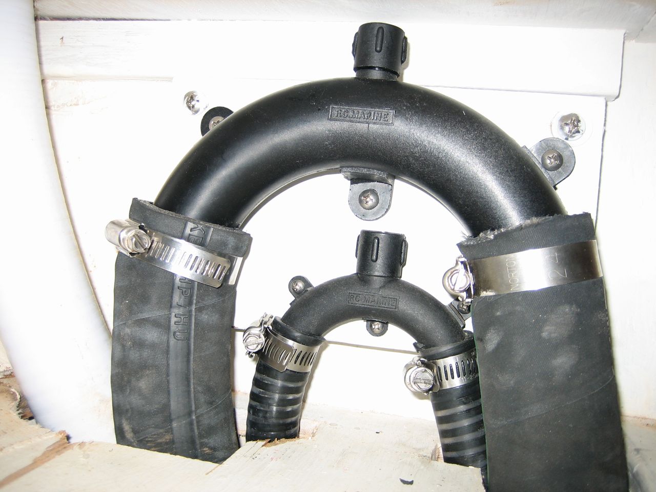
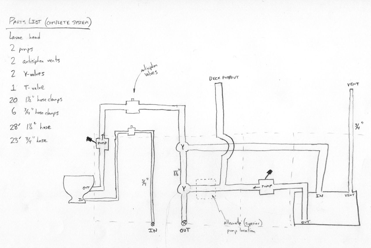
Designing a plumbing setup from scratch is not easy–you need to include hose and y-valves and pumps and fittings to fulfill the following actions: 1) Pump head to holding tank 2) Pump head to ocean 3) Pump holding tank to ocean 4) Let holding tank be sucked out from deck fitting.
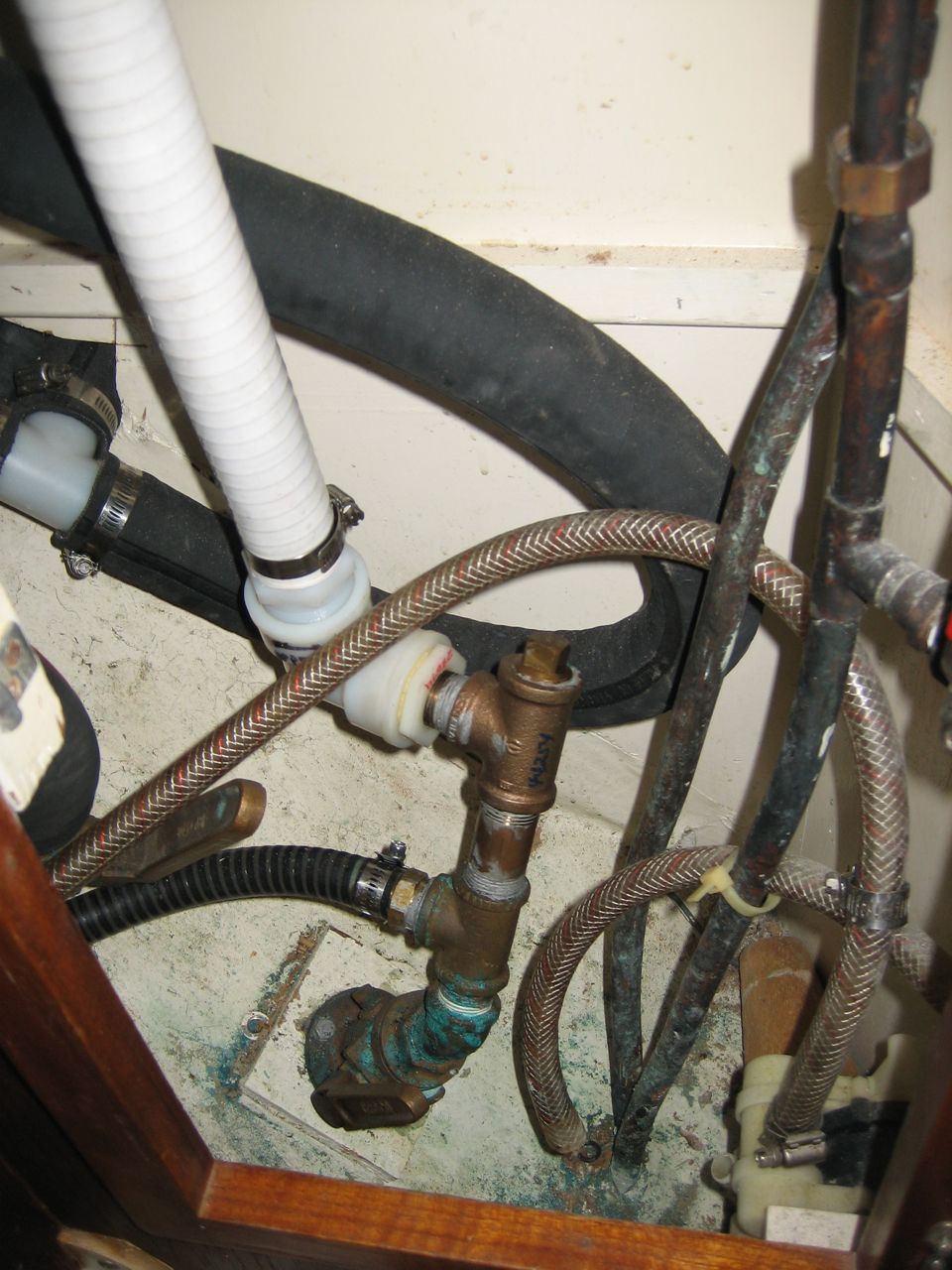
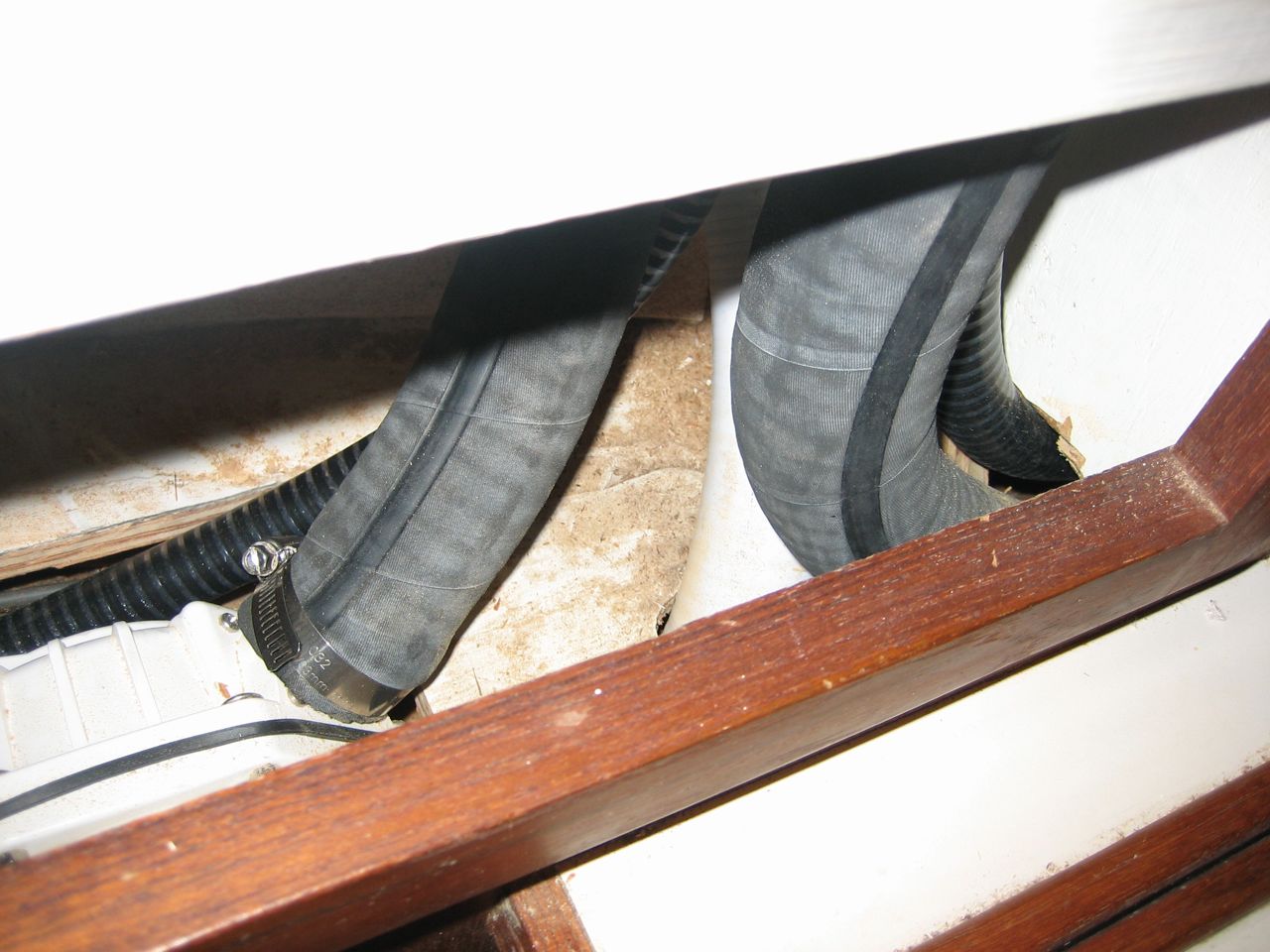
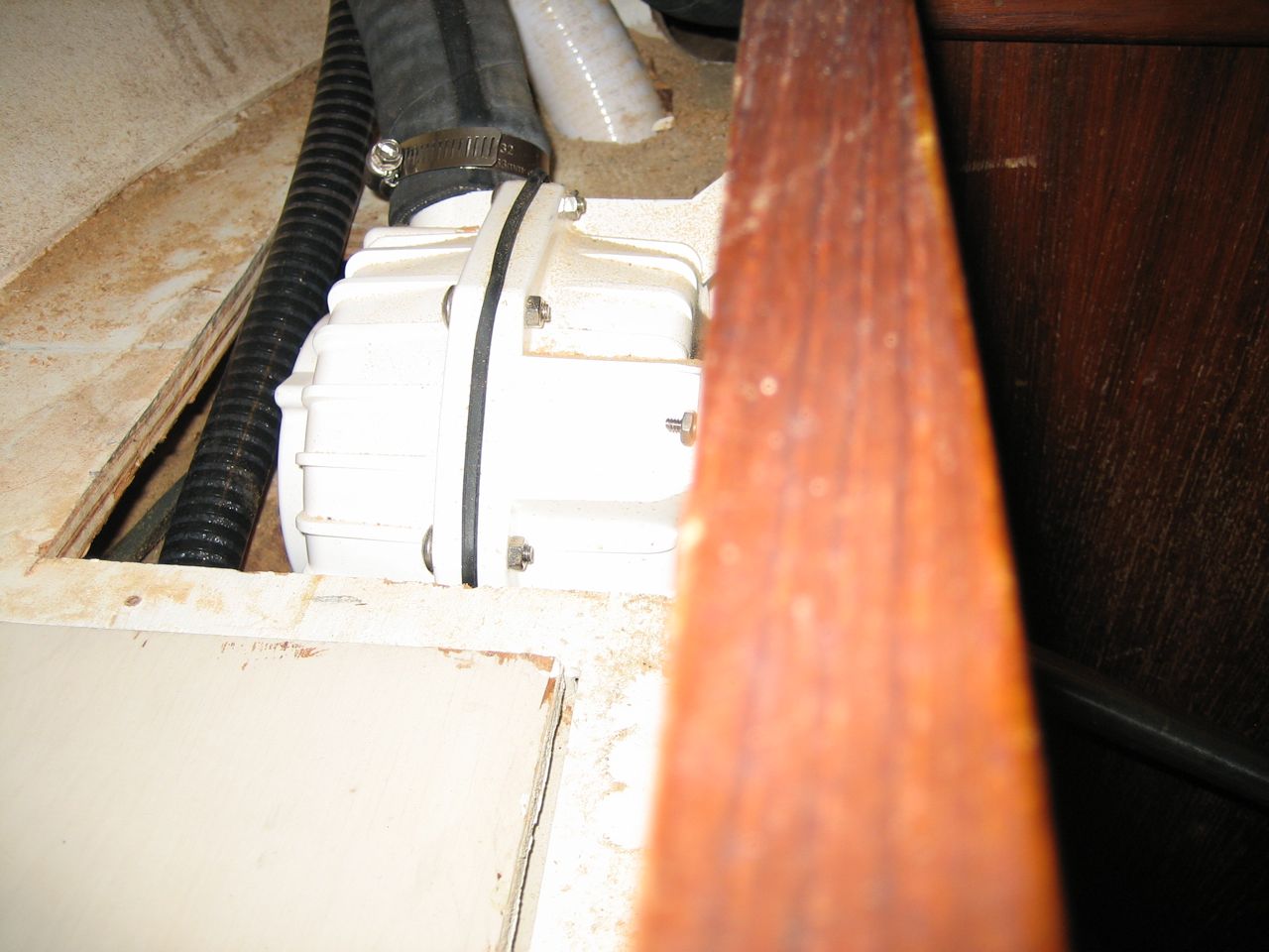
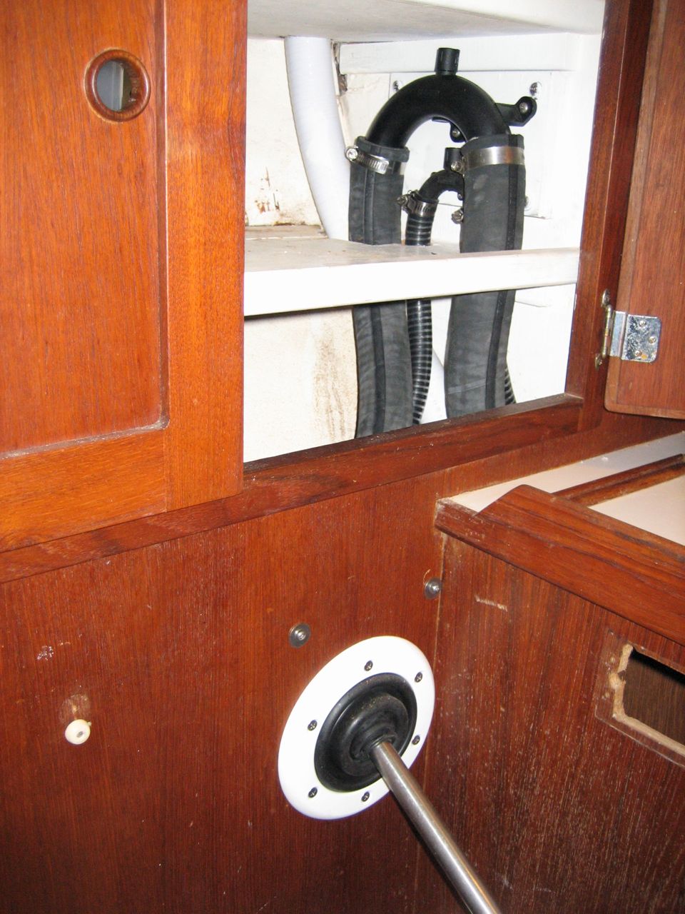
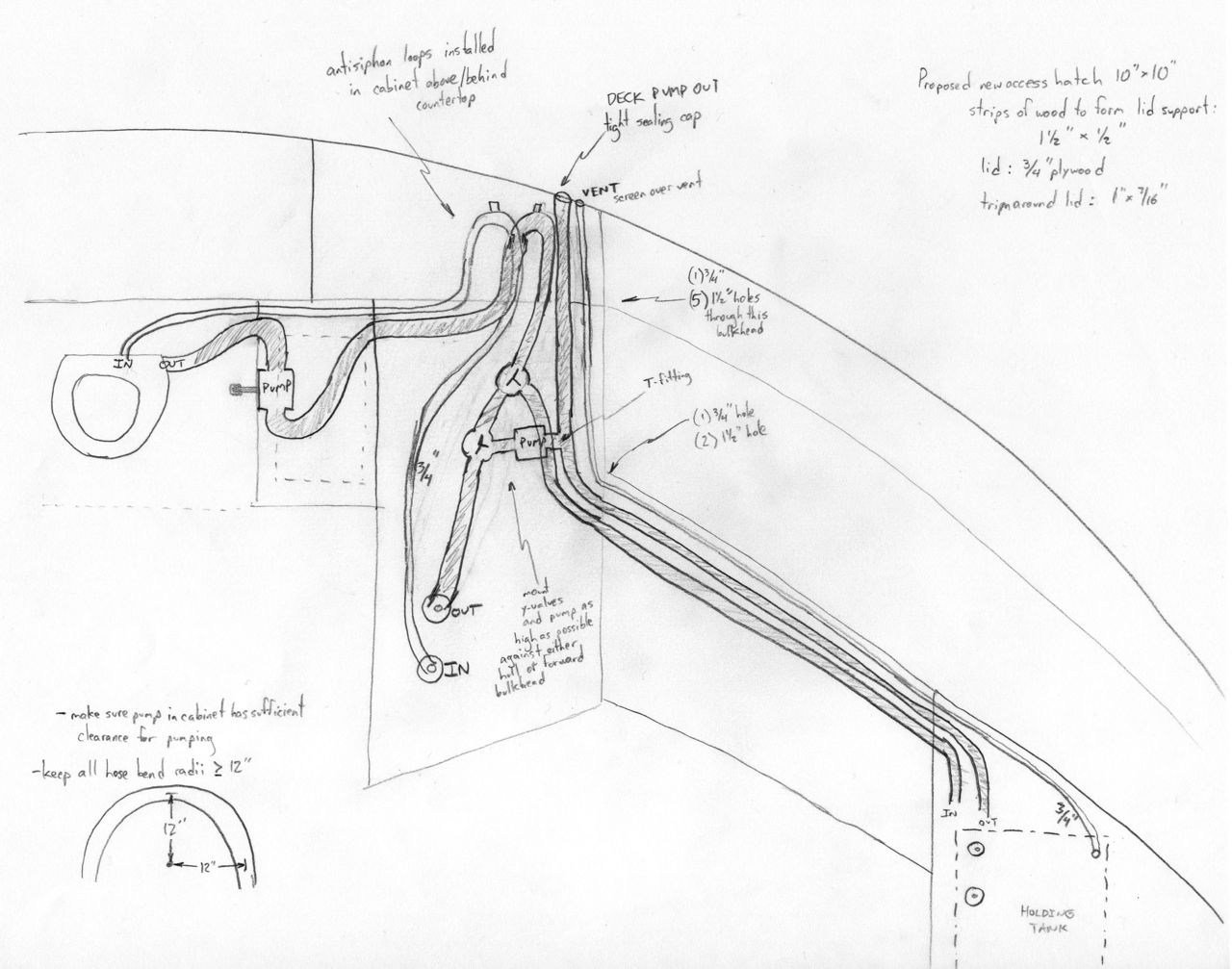
Check out the diagrams in the gallery below. First I made the abstract schematic of how I wanted everything connected. But the hardest part is getting all the components to fit in the available space, so then I made the schematic of how the system would fit into which spaces of our boat. As it turned out, I deviated from the plan, and moved the location of two anti-siphon loops to a neighboring cabinet (to the left), and the pump went into the wall behind then head instead of the cabinet adjacent to it, but everything else fit where I thought it might.
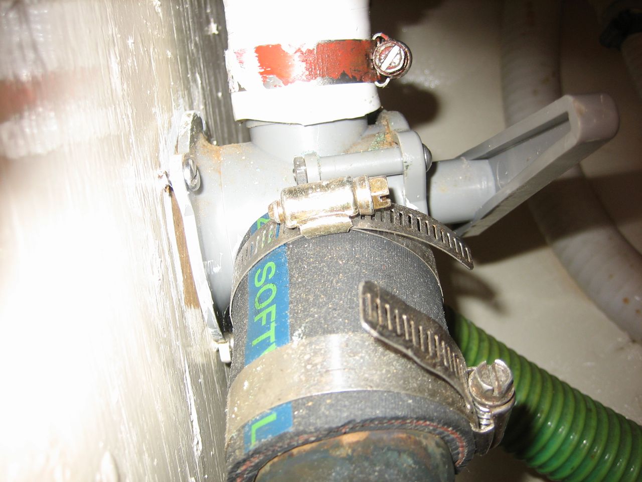
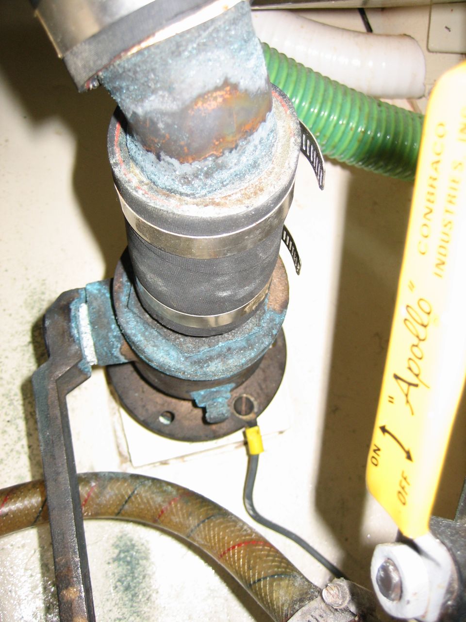
The biggest hurdle was the last 10″ section of hose going from y-valve to seacock. The y-valve’s fitting, like everything else that touches poop, is 1-1/2″. But the through-hull was not. I think the previous owners installed a “full-flow” 1-1/2″ fitting, which has a 1-1/2″ internal diameter, and 1-5/8″ external hose barbs. I spent hours over a period of a week trying to fit an 1-1/2″ hose onto that seacock; I used soap to lube it, I used a hair dryer to soften it, then I used a heat gun to soften it, I even soaked the hose in boiling water. Nothing was going to work, it was a futile attempt. In the end, I used a larger hose and built up the 1-1/2″ fitting on the y-valve to accomodate the larger hose (beware! if you try to just clamp a larger hose down onto a too-small fitting, it will leak!). The svendsen’s people saved the day by pointing me to a product designed for plumbing repairs: a resin-impregnated fiberglass tape that is activated by air or water. Just pull it out of the sealed package, wrap it tightly around the fitting to build it up as much as you want, wait an hour, then sand it down. 1-5/8″ hose fit over it perfectly.
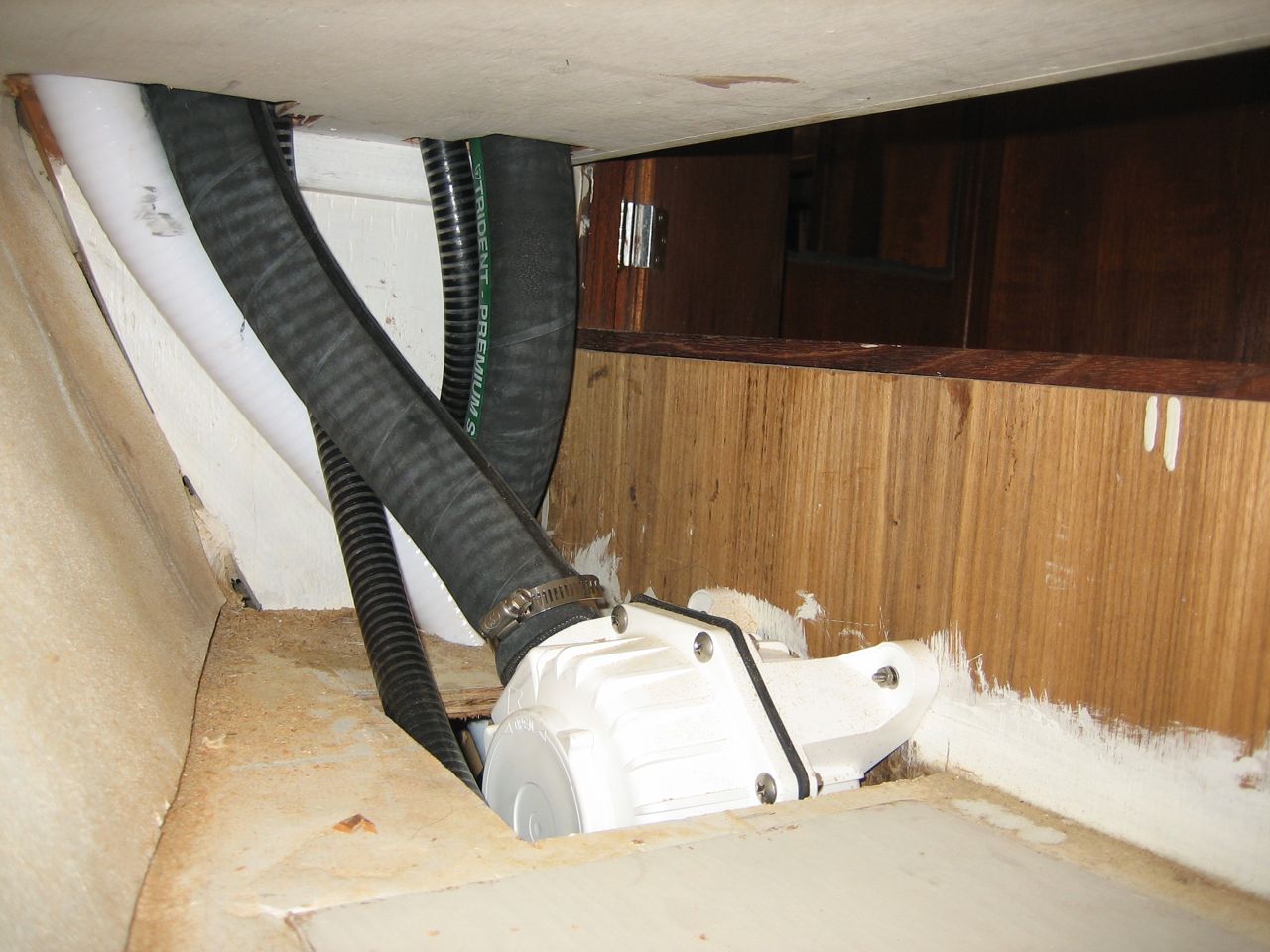
Another special feature of our head installation: I decided to add a second vent to the through-hull, opposite the existing one (old vent is to port, new vent is to starboard). The thing with stinky odors is this: the stink is caused by the anaerobic bacteria. If you keep the system aerated, you eliminate the bacteria that causes the smell. Our old hose was 3/4″ diameter and 12′ long from tank to through hull. It doesn’t take a genius to realize that very little air is going to flow through that thing, without any cross-ventilation going on. So I added some cross-ventilation in the for of a second vent. I used 1-1/4″ hose, which is particularly large as far as vents go, but it’s about a 12′ run from the holding tank to the vent through-hull so the air needs every assistance to flow. Hopefully it will help keep our boat stink-free.
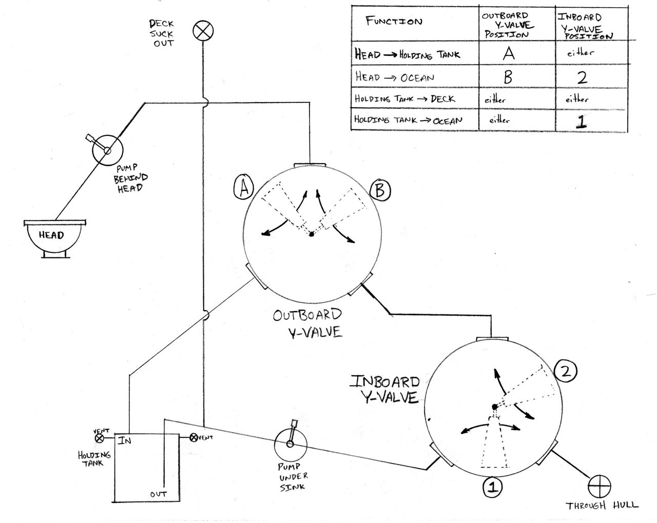
The last thing I did (just did it this morning, actually) was make up a diagram of how the y-valves need to be oriented for different shit-paths. That’s the last image in the gallery below. When I mount it on the wall next to the toilet, it will correspond with the y-valves and handle positions on the backside of the cabinet, so it will be easy to know by feel where to put each handle (at least that’s the idea–time will tell whether it works).
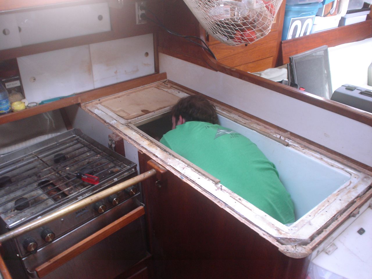
We’re in the process of redoing the refrigeration. Unlike other posts, in which the job is already completed and I give a very brief recap, I’m putting down my notes and choices while currently working on this project.
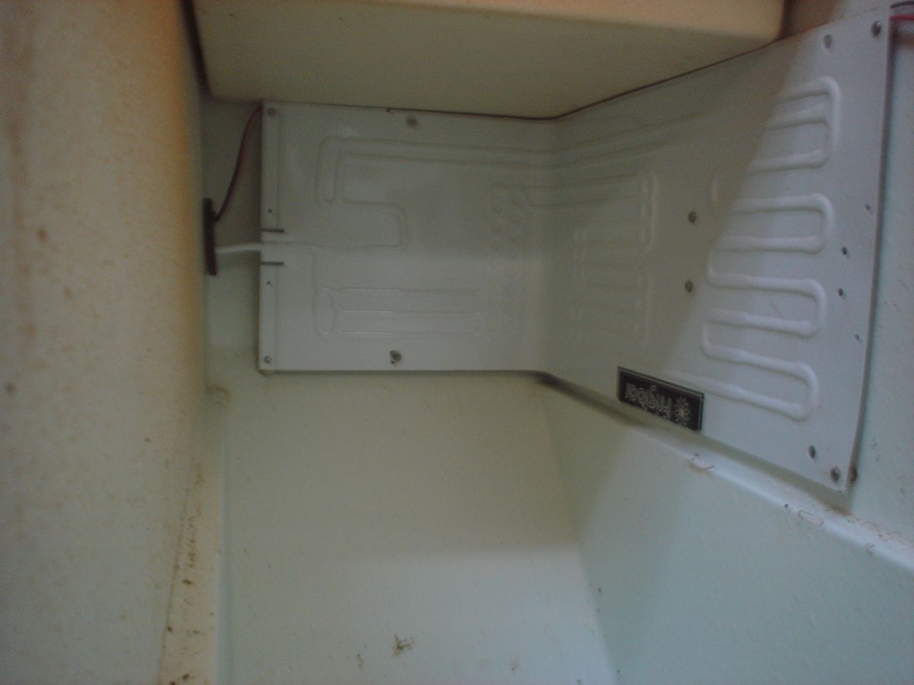
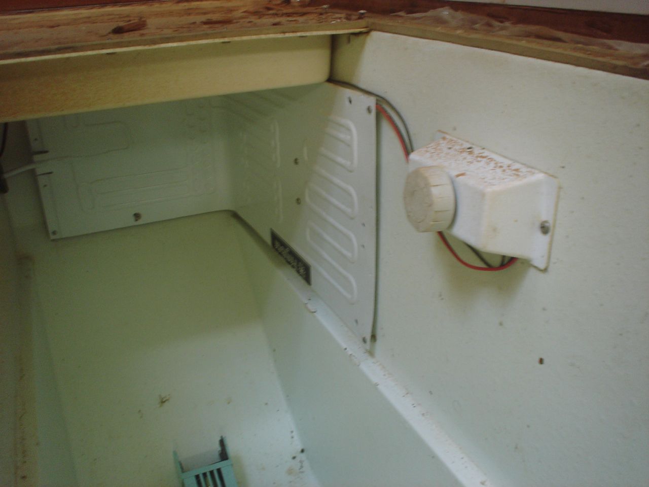
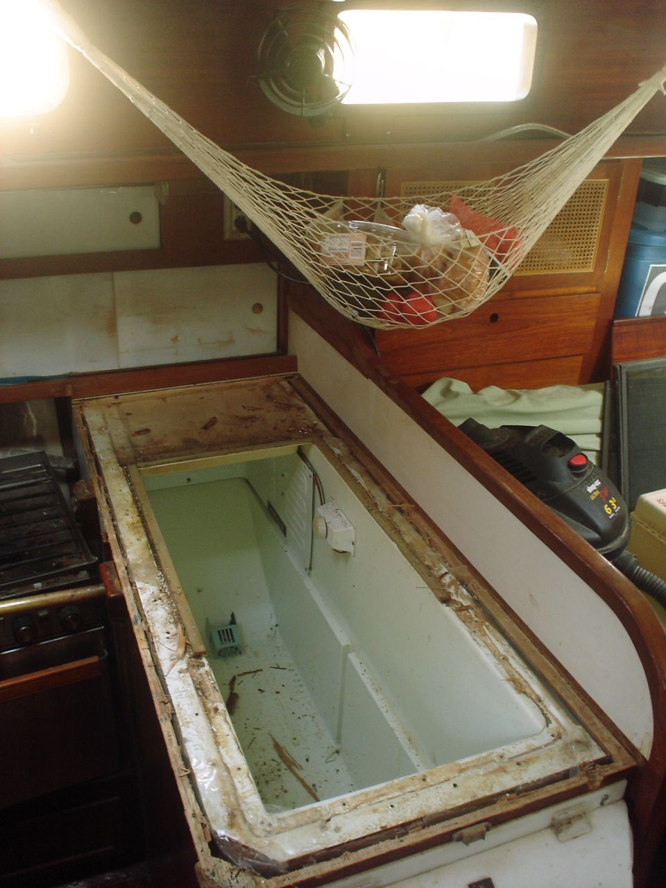
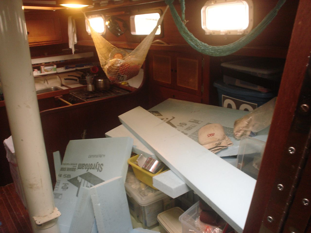
Our compressor was kicking on and off erratically for a period of probably 6 months after we started using the boat. Each time it stopped working, jonny would lose a bunch of food that went bad in the icebox, and then he would have to clean it out when it started smelling, etc. Finally we gave up and Jonny has been living without refrigeration for 6 months now. Also, I decided from my research that the insulation in our box was inadequate: 1) it’s 30 years old (it deteriorates big time in r-value) 2) there was 1.5″ on the top and 3″ on the rest of the box; there should be at least 4″.
At first we made minor attempts to figure out what was wrong with the old system – prior to inviting guys from home renovation Tulsa OK. I wasn’t going to participate in that attempt though, because I was convinced that we would need a whole new system regardless and I didn’t want to sink any time into messing with the old one. If I was going to go at it full bore, I wanted us to do it right: first reinsulate the box, then replace the whole refrigeration setup. Jon and Jonny were not psyched about this idea–justifiably so, because it represented a collosal amount of work and a couple thousand dollars–and weren’t ready to pull the trigger on a new system. I didn’t try to persuade them, I just said that I would let them take care of repairing the old compressor, then. 🙂
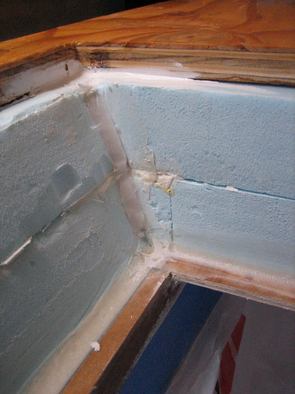
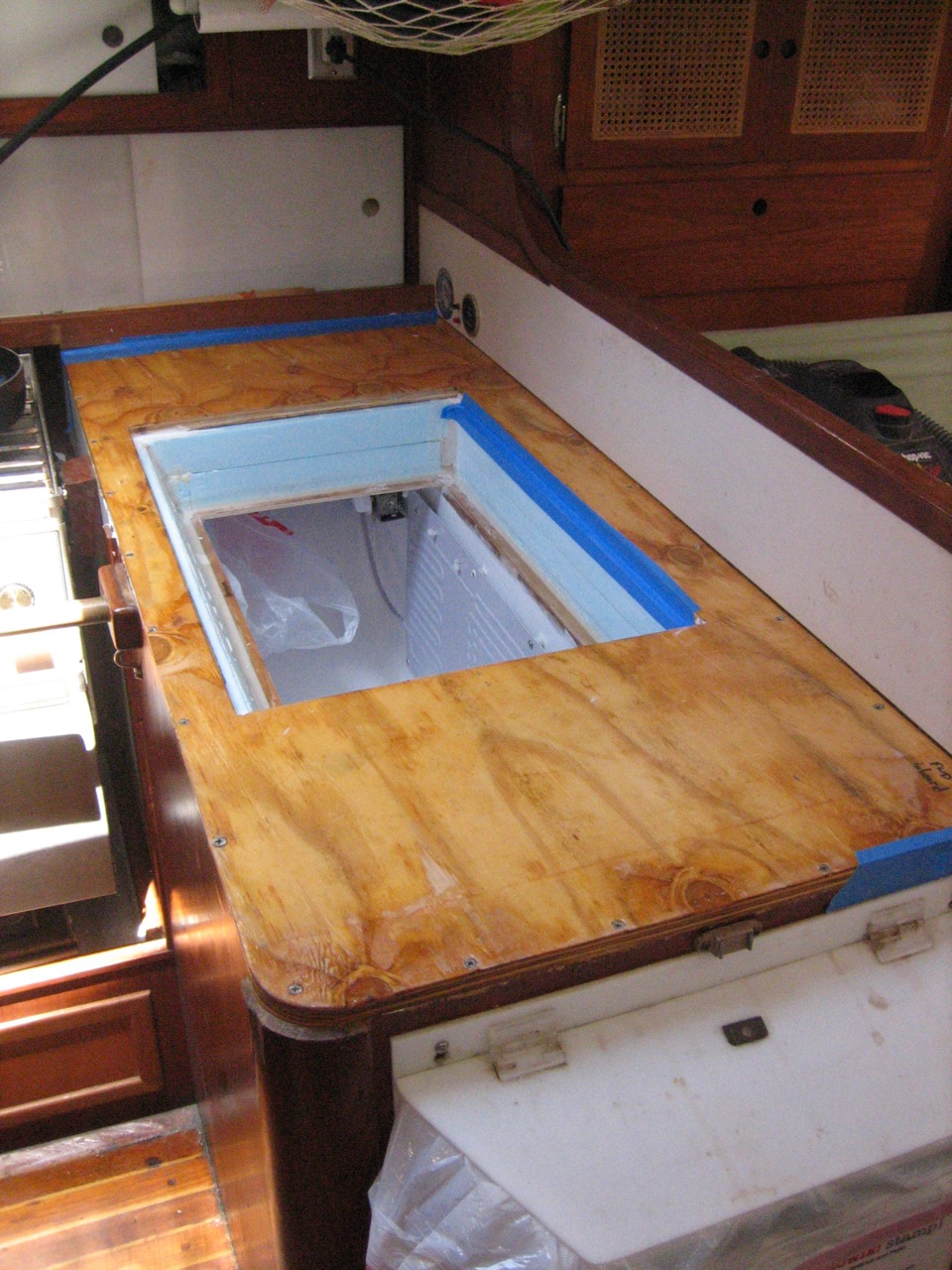
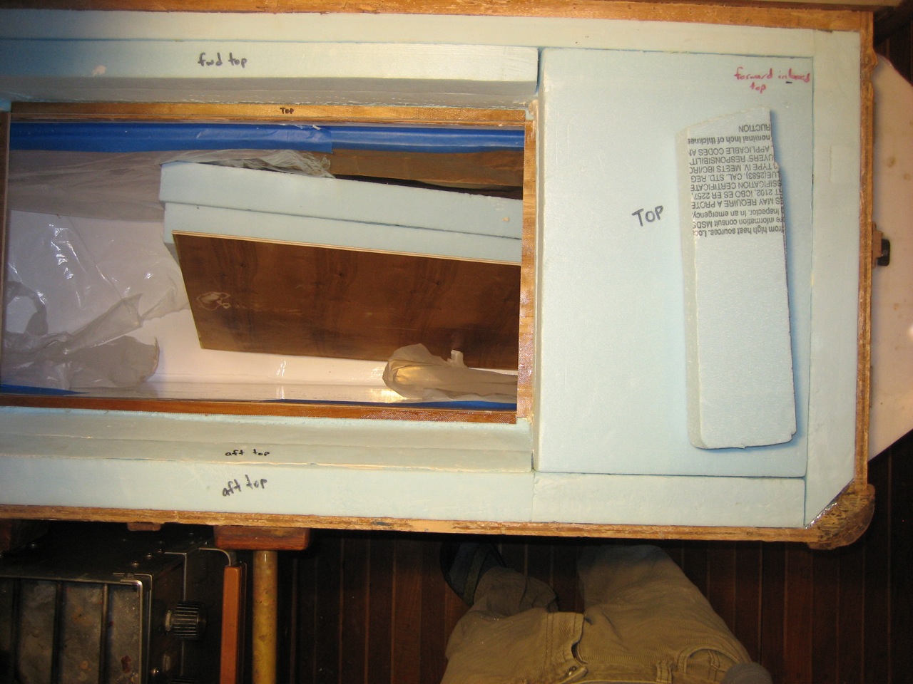
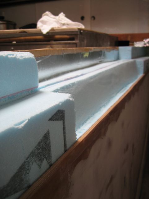
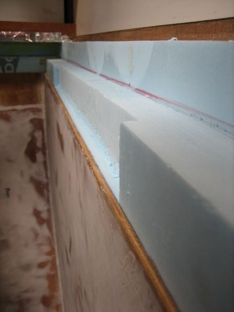
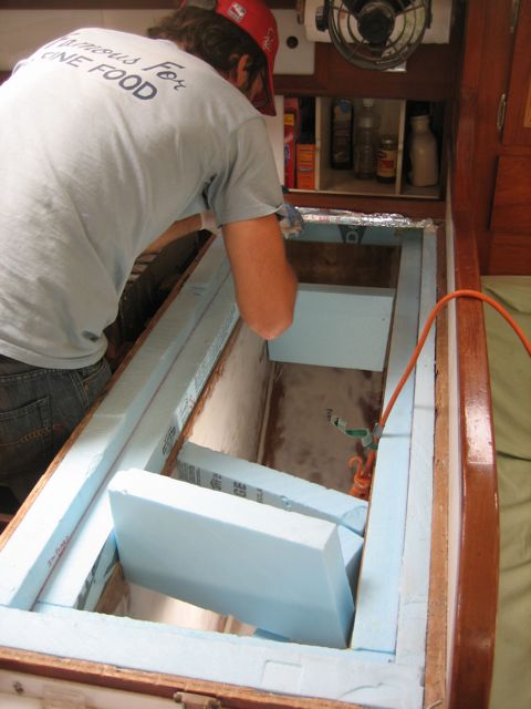
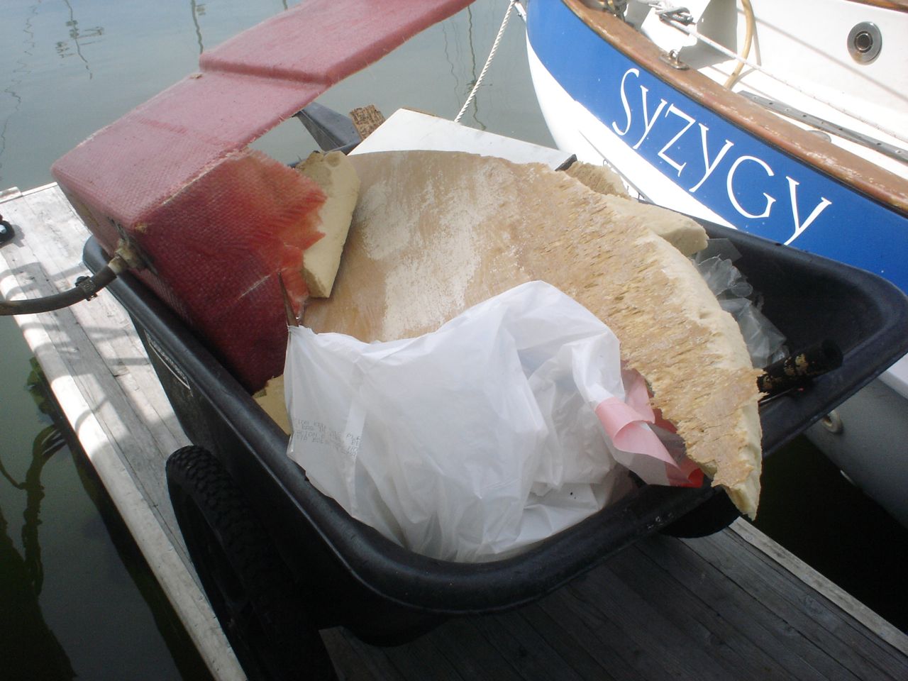
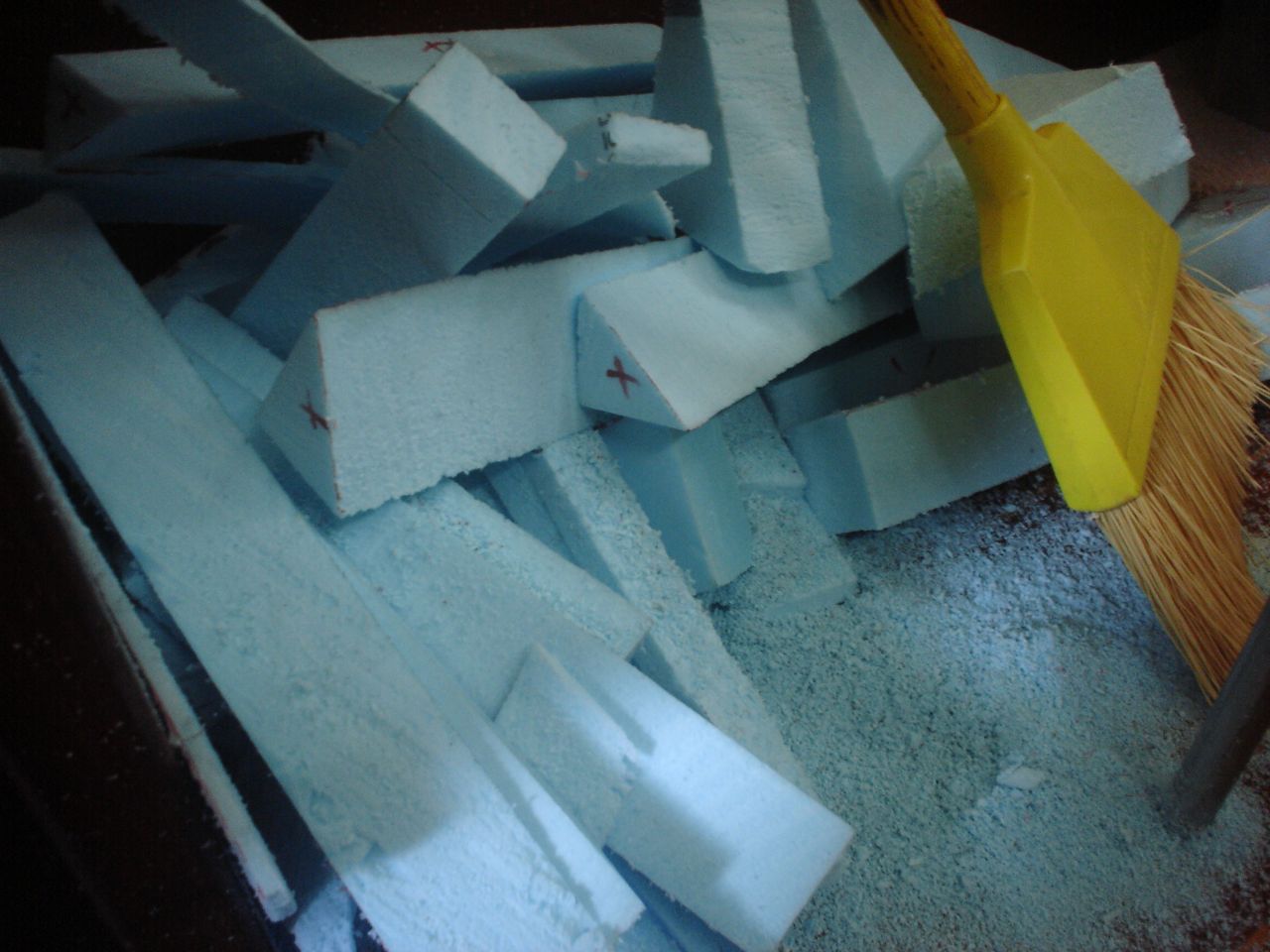
In April I started tackling it. I drew up detailed plans for the box and a list of steps, so that we could move as efficiently as possible once we started. I decided on 4″ all around of Blueboard–an extruded polystyrene made by Dow–for our insulation. Blueboard doesn’t have the highest R value of all the insulations available, but it is the most impervious to moisture and that means that after just a year or two it might be outperforming your other choices (lots of people use polyisocyanurate foam–commonly available at home depot, it looks like yellow foam with a foil backing–it absorbs moisture pretty readily!). The only place within 50 miles that sells the blueboard is Pacific Supply in South San Francisco, and the Dow representative I talked to told me that their west coast machine only makes boards 2′ wide. The design of the lid is the hardest part. You want it to ideally have the following features: double gaskets (top lip and bottom lip), flush mounted in the counter, minimal gap all around, angled front surface so it will open without jamming, easy to clean pretty finished surface. Since you build the box from the bottom up, it can be tricky to get the interior of the box and the countertop to be perfectly spaced for the exact thickness lid, etc. There are many ways of building it–the easiest is to buy a premade one for ~$500, from Glacier Bay for example.
Initially I knew nothing about how the refrigeration system worked, and I decided to buy an Adler-Barbour Cold Machine and evaporator plate, which come precharged with refrigerant and ready to go, and just hook them up and be done with it. The total cost would be about $1300, and it could be installed in a day. I was all ready to buy it when I ran into Marcus on the dock and stopped by to check out his new system. Marcus was also in the process of rebuilding his whole refrigeration setup, including reinsulating (with vacuum panels!) two iceboxes, and building two compressor setups from parts himself. He purchased all the specialized refrigeration tools necessary to do the work himself, including a vacuum pump. Talking to him I was daunted by the amount of work and complication it represented, and in my mind I was still saying to myself “hell with that! I’m buying the adler-barbour!” But Marcus suggested that I take a look at a website called rparts to at least see if there was a cheaper option for me.
I checked out rparts, looked at their do-it-yourself kits, looked at the list of parts contained in the kits, looked at the price ($800), and decided that maybe I would learn how to do refrigeration after all. So I downloaded the installation manual for the 1M kit they sell, and using the manual and the rparts website and Kollman’s forum I sat down with Calder’s refrigeration book (which I had already read twice, without much illumination) and figured it all out finally. With the right combination of resources, each section of Calder’s book was now like a lightbulb going on. It was gratifying to finally understand an area which had previously seemed so baffling to me. I am extremely indebted to Marcus for inadvertantly convincing me to learn it and do it myself. “Do it ourselves” is our modus operandi for everything else on the boat, and it was out of character for me to want to simply pay money for a setup and not have to think about it or understand it or put in ridiculous amounts of time and labor for its installation.
I started by dorking out with Calder’s refrigeration book, and measured our box to calculate the surface area and thereby estimate the heat loss, in order to size the refrigeration capacity appropriately. Here is my diagram:
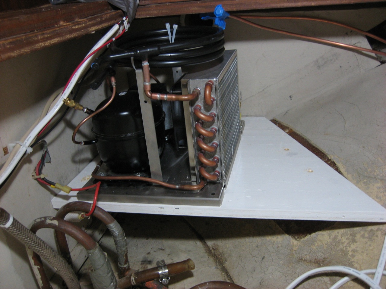
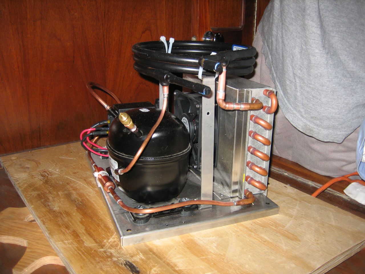
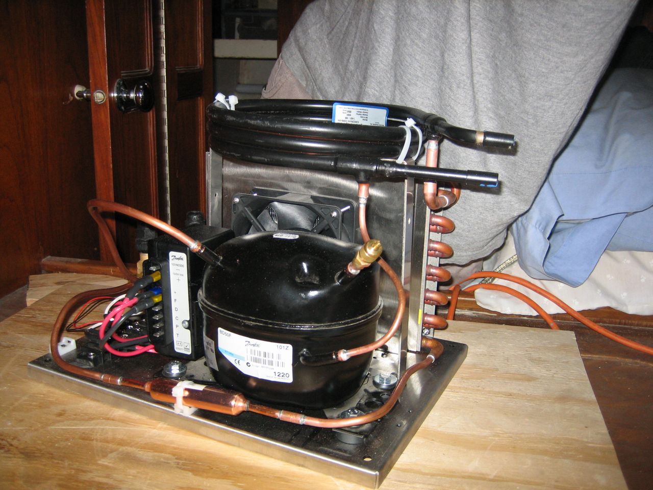
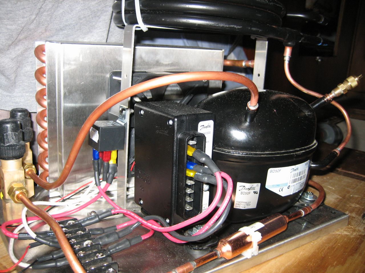
You can think of the refrigeration system as a closed circuit of refrigerant with two heat exchangers: the heat exchanger in the icebox is the “evaporator”; the heat exchanger mounted with the compressor is the “condenser”. The compressor itself is a just a refrigerant pump; it is the block ovoid shape easy to recognize in most pictures.
There are two common types of evaporators: the “evaporator plate” and the “holding plate”. The evaporator plate is the simplest, cheapest, most maintenance free of evaporators. It is a roll bond aluminum plate–“roll bond” describes the manufacturing process–that contains a network of channels through which the refrigerant passes. Inside the icebox, the refrigerant passes through the plate and makes it cold, and then the plate cools the air around it in the box (which is why the plate must have space on all sides of it, so that all of the surface is working to cool the box rather than just one side). The holding plate is actually an evaporator immersed in a specialized fluid (a “eutectic” fluid). The refrigerant passing through the evaporator freezes the eutectic fluid, and then over a number of hours the eutectic fluid keeps the box cold. Essentially the holding plate is a big reservoir for holding the cold, just like a big block of ice. With a roll-bond evaporator plate, the compressor comes on and off more frequently, for shorter periods of time. With a holding plate, the compressor comes on much less frequently (perhaps as little as once a day) but runs for a long time to completely freeze the eutectic fluid. Which is better? Entirely depends on your system, and there is continued debate.
There are two common types of condensers: air-cooled and water-cooled. The air-cooled condenser is a series of fins (not unlike a car radiator) through which a length of the refrigerant tubing runs, and usually there is a fan to blow air over the apparatus. The hot refrigerant passes through this and hopefully cools off in the process. Obviously this is more likely to happen if the air temperature where the condenser is located isn’t 120 degrees (if it is you’re totally screwed). The water-cooled condenser is more like the heat exchanger on the diesel engine: it circulates seawater to cool a length of refrigerant tubing. There are a couple different models, “tube in a tube” and “shell type”, take a look at the offerings on the Rparts website. There are a few more exotic water-cooled solutions out there; the “keel cooler” is a design that takes the refrigerant to the ocean instead of bringing the seawater to the refrigerant. My favorite is the tube in a tube type (maybe because Calder seems partial to those). The refrigerant goes through the center tube, and an electric motor pulls water from the ocean and pumps it through the outer tube and then back out of the boat. Air-cooled condensers are simple and require power to run a fan (~.2A). Water-cooled condensers are more complicated because they require plumbing seawater from a through-hull and back out, and require power to run a pump (~1.5A). The water-cooled condensers are much more effective at efficiently removing heat from the refrigerant, but until the air temperature gets really hot, the additional power required to run the water pump outweigh the efficiency gains in heat transfer. The cutoff point of efficiency is debated (and different for every installation). Calder thinks that water-cooled is essential for a functioning system in the tropics, Kollman is completely against water-cooled because of the increased complexity, expense, and failure rate.
A refrigeration system is a heat pump–it moves heat from the evaporator to the condensers, sucking heat out of the icebox and dumping it off at the condenser. If you just pumped a liquid around in circles, from the evaporator to the condenser to the evaporator to the condenser, etc, then you would indeed remove some heat from the icebox and dump it at the condenser. However, you can’t suck up much heat just by warming up a liquid and then cooling it off. The real way to suck up heat and drop it off elsewhere is to use a phase change to your advantage. Consider a quart of water on the stove. It takes 320 BTU of energy to heat that water from 33 degrees F to 211 degrees. Then, to heat that water from 211 degrees to 213 degrees, it takes 1934 BTU. At 212, the H2O changes from water to steam, and during that entire process you keep dumping in large quantities of energy and the temperature stays the same–all the energy goes into the conversion from liquid to gas. The energy required to do a phase change from water to steam is way greater than the energy required to change the temperature. So we use that phase change to make refrigeration possible. We don’t use water though, because we want the phase change to take place around the 20 degrees F in our refrigerator (not very helpful to us for it to take place at 212 degrees). We pump a liquid to the evaporator, and then let it expand into a gas; that expansion to a gas sucks huge amounts of heat out of the box. Then back at the compressor we compress the gas, which heats it up (essentially exchanging “pressure energy” for heat). Then we send it through the condenser, where the the hot gas turns back into a liquid and dumps off all its heat in the process. Then we sent the liquid back to the evaporator, where it turns into a gas again . . .
Once I decided that I was going to buy the kit and parts from Rparts and build my own system, I was free to design a system that includes both condensers: air-cooled for cooler climates and water-cooled for when it gets really hot. To alleviate Kollman’s concerns about the water-cooling, which I take seriously, I am going to take precautions against galvanic corrosion of the water-cooled condenser by electrically isolating it, and I’m going to wire in a PWM circuit so that I can turn down the power consumption of the water pump.
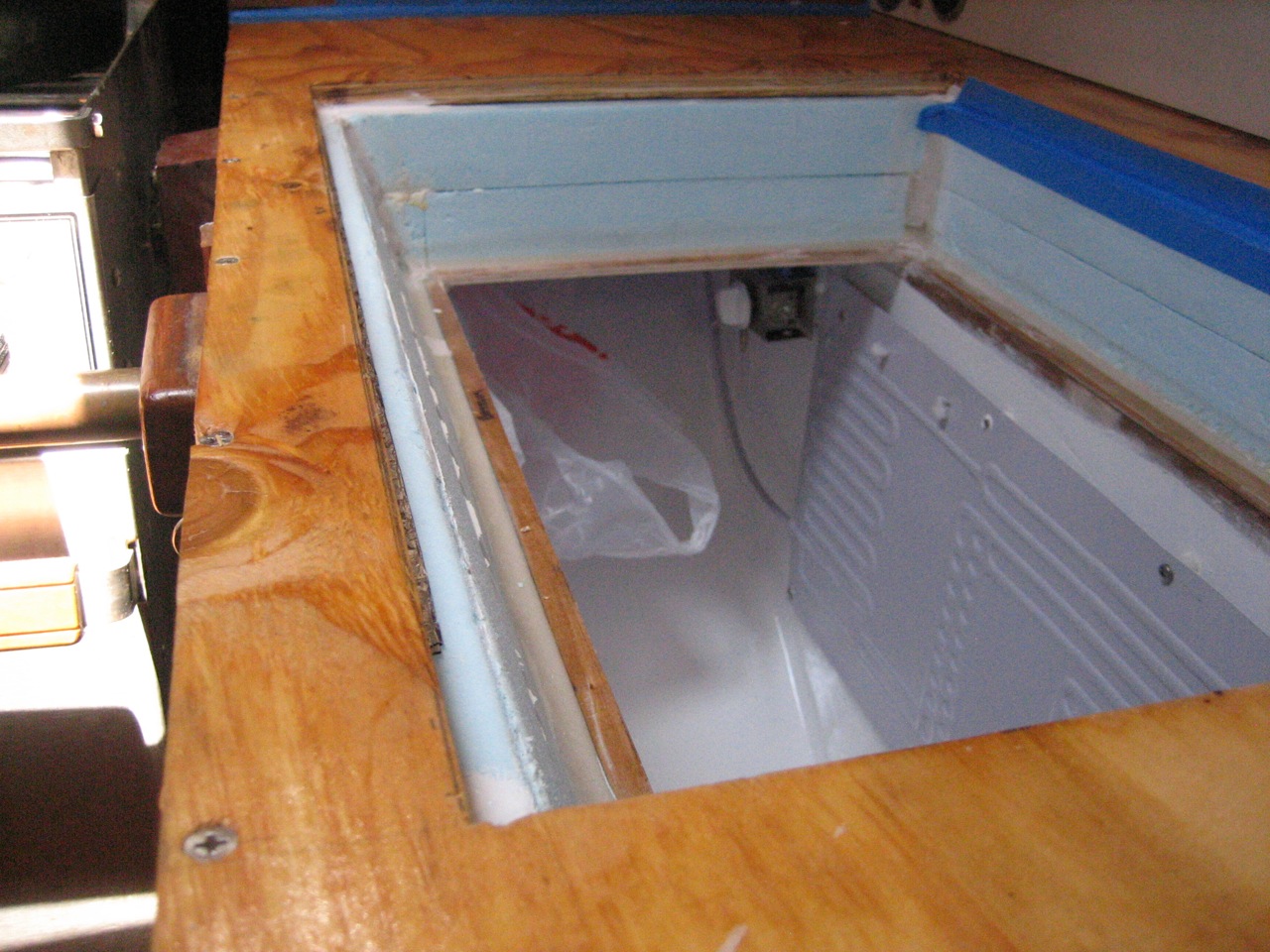
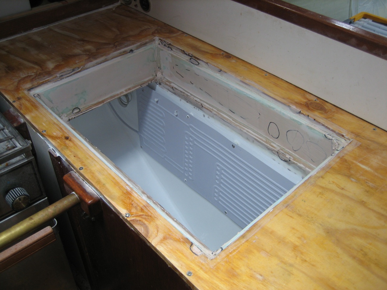
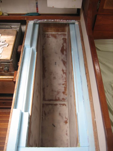
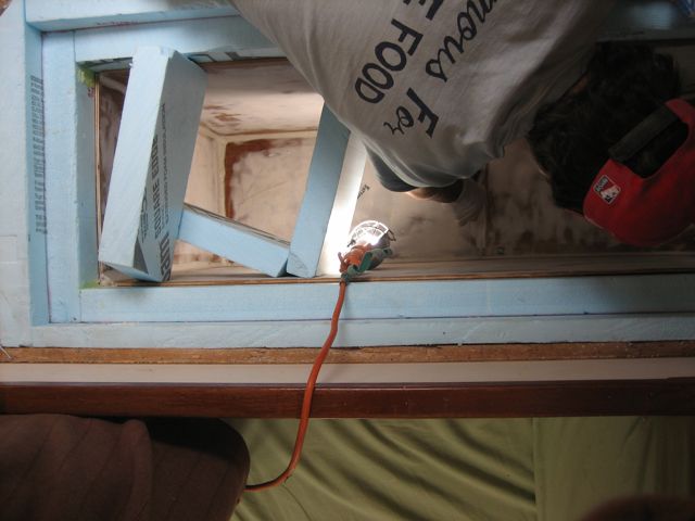
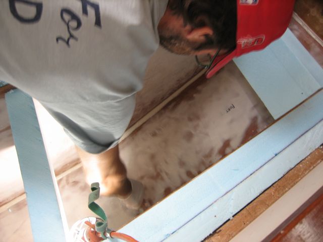
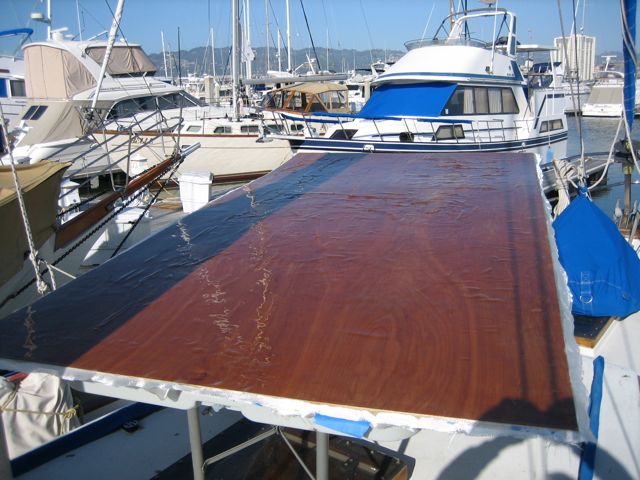
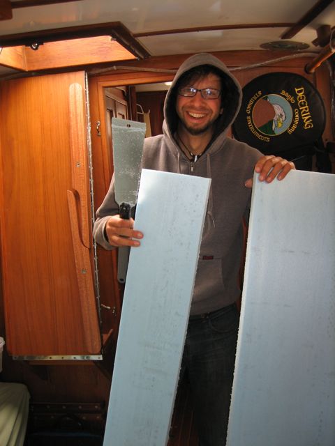
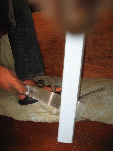
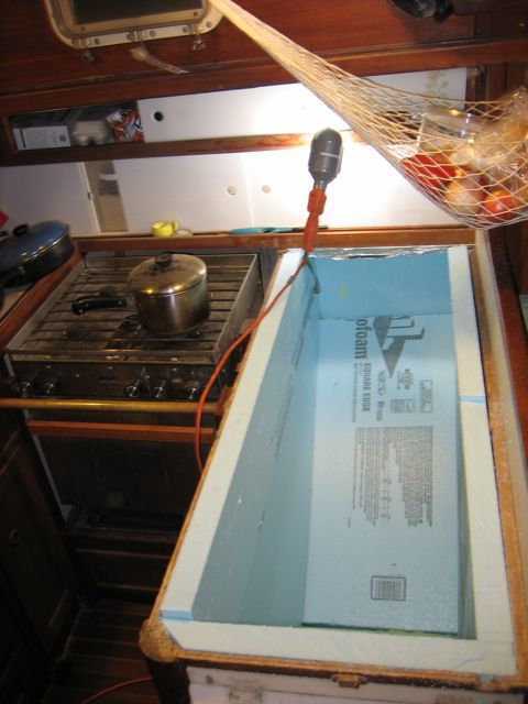
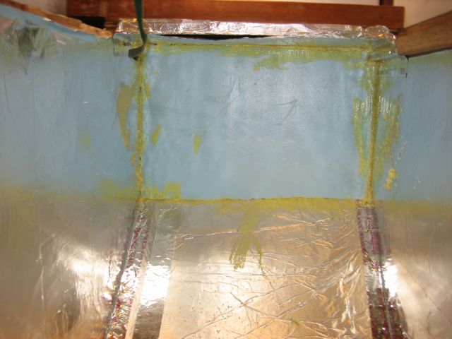
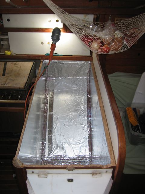
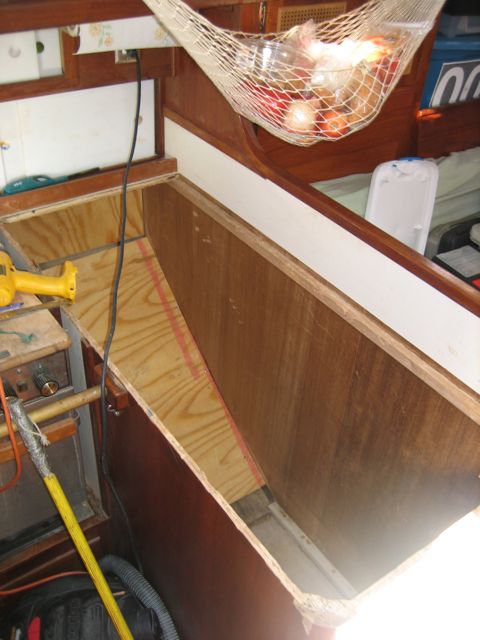
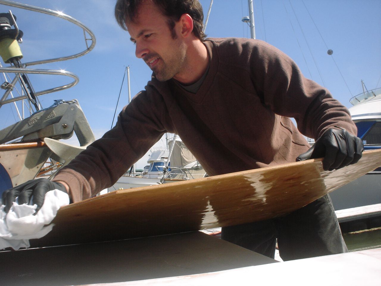
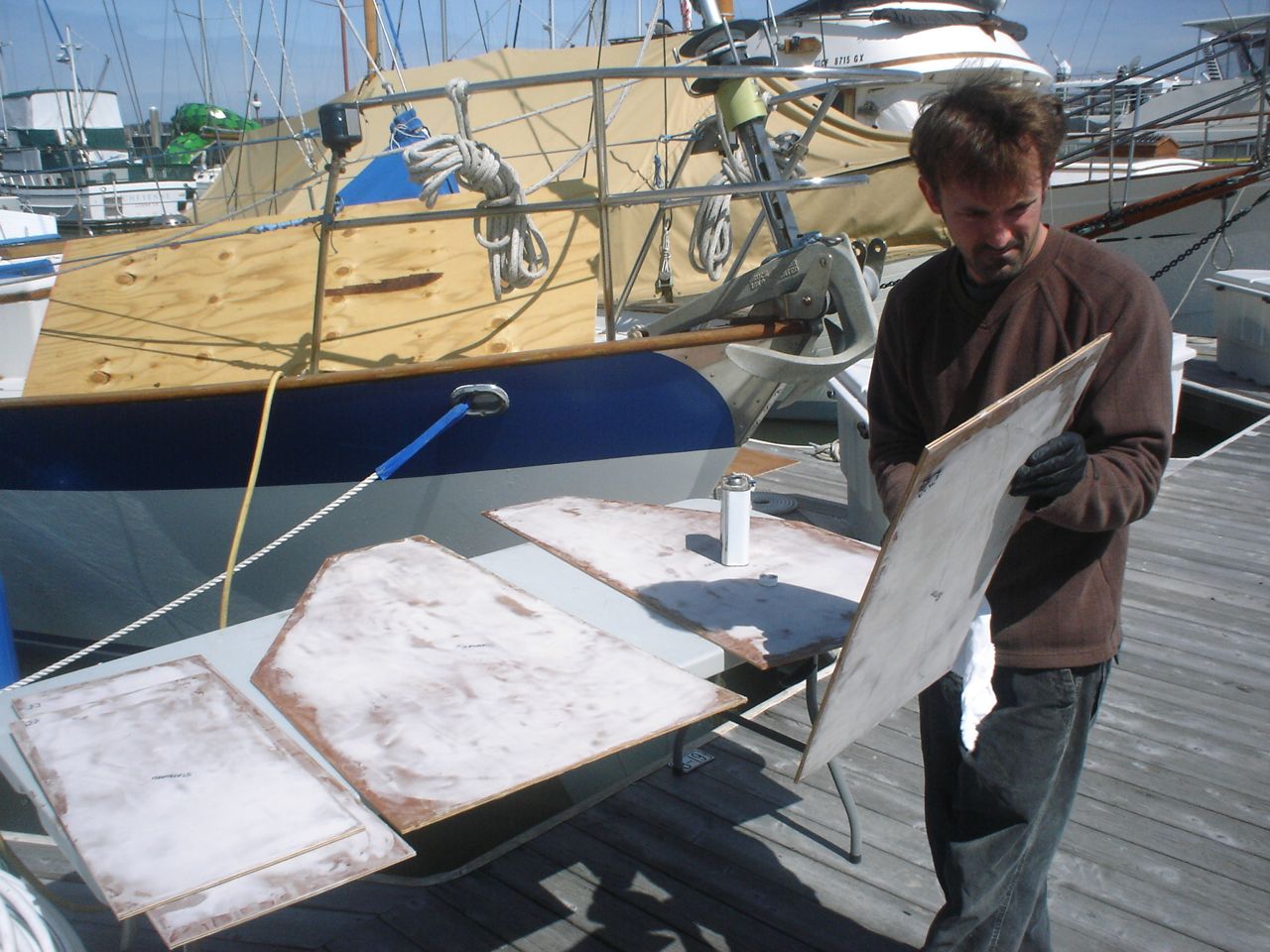
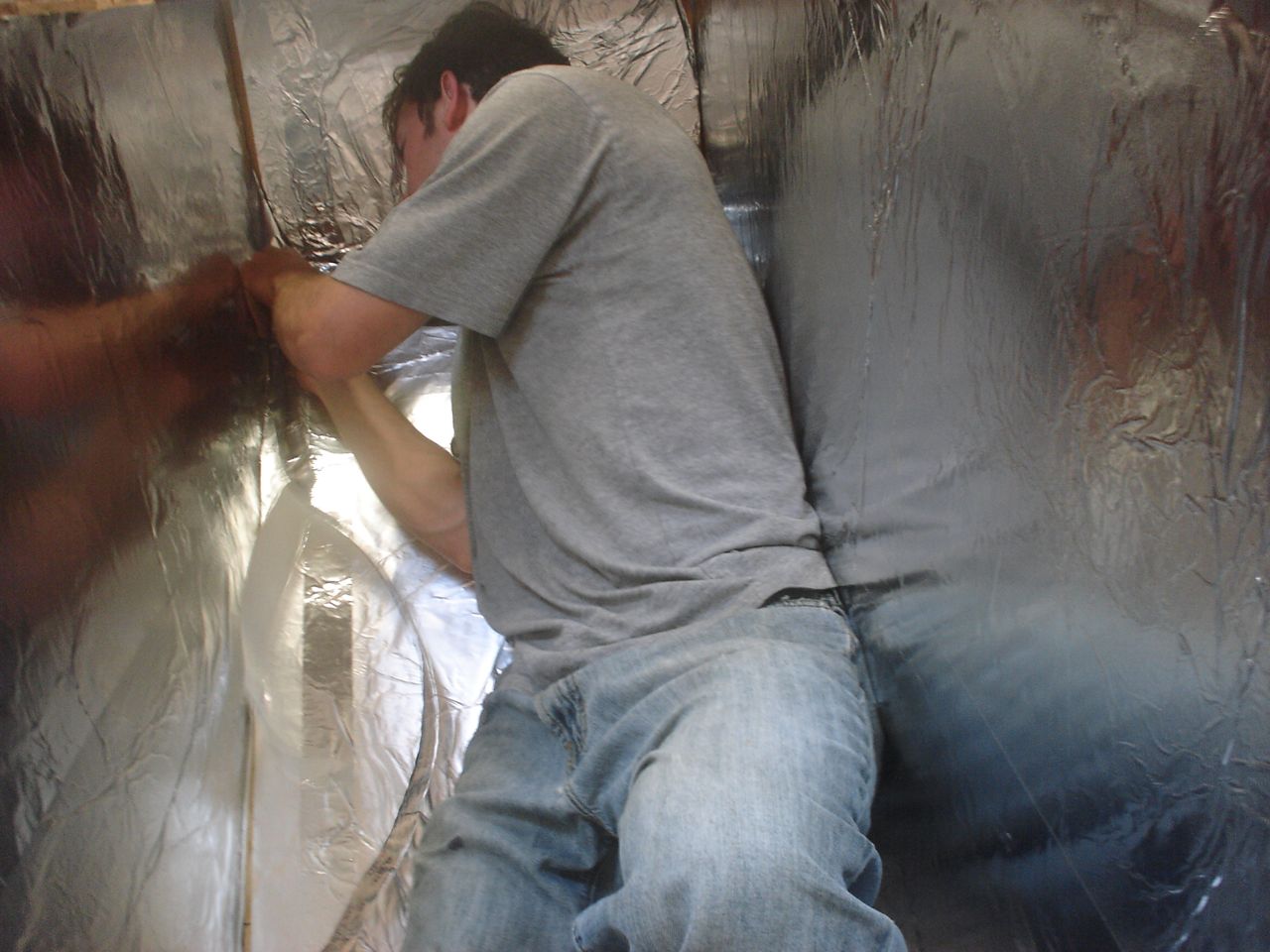
Jonny and I ripped out the old box in one day–the entire thing. The next day I picked up 18 sheets of 2’x4′ Blueboard 2″ thick from Pacific Supply. We lined the inside with a layer of aluminum foil, used spray adhesive to stick it in place. I taped the seams with metal tape. Then we made a huge mess cutting up the foam with the Dozuki saw–pretty easy and quick actually–and pieced most of the insulation in place. We bought two thin sheets of plywood and glassed over them with a few layers of fiberglass, then faired them smooth with quikfair, cut them to fit, and built a box inside the insulation. Jonny glued all the edges together with fillets of thickened epoxy, then we sanded them fair, and painted the inside of the box with two layers of Primekote, an epoxy primer.
That’s as far as we’ve got. I ordered the refrigeration parts from Rparts, and we need to wait to put the evaporator into the box before we put the lid on it and build the hatch for it. So we’re probably 30% done with the job.
After doing the jib car tracks, we knew these would eventually have to be done as well. While adding the new portlights we discovered a fairly significant leak on the starboard side that we were 99% certain was coming from the staysail track. So we pulled off the interior trim to access it, removed the track, cored the holes, plugged them with epoxy, drilled new holes through the epoxy plugs, and remounted the track using 3M 4200 UV for a sealant.
When we drilled and cored the new holes it was easy to look at the fresh, wonderful balsa core and see that the track hadn’t been leaking (the port track, on the other hand, showed some minor signs of leaking). So we were wrong about the source of the leak and now we have to pull something else off the deck.
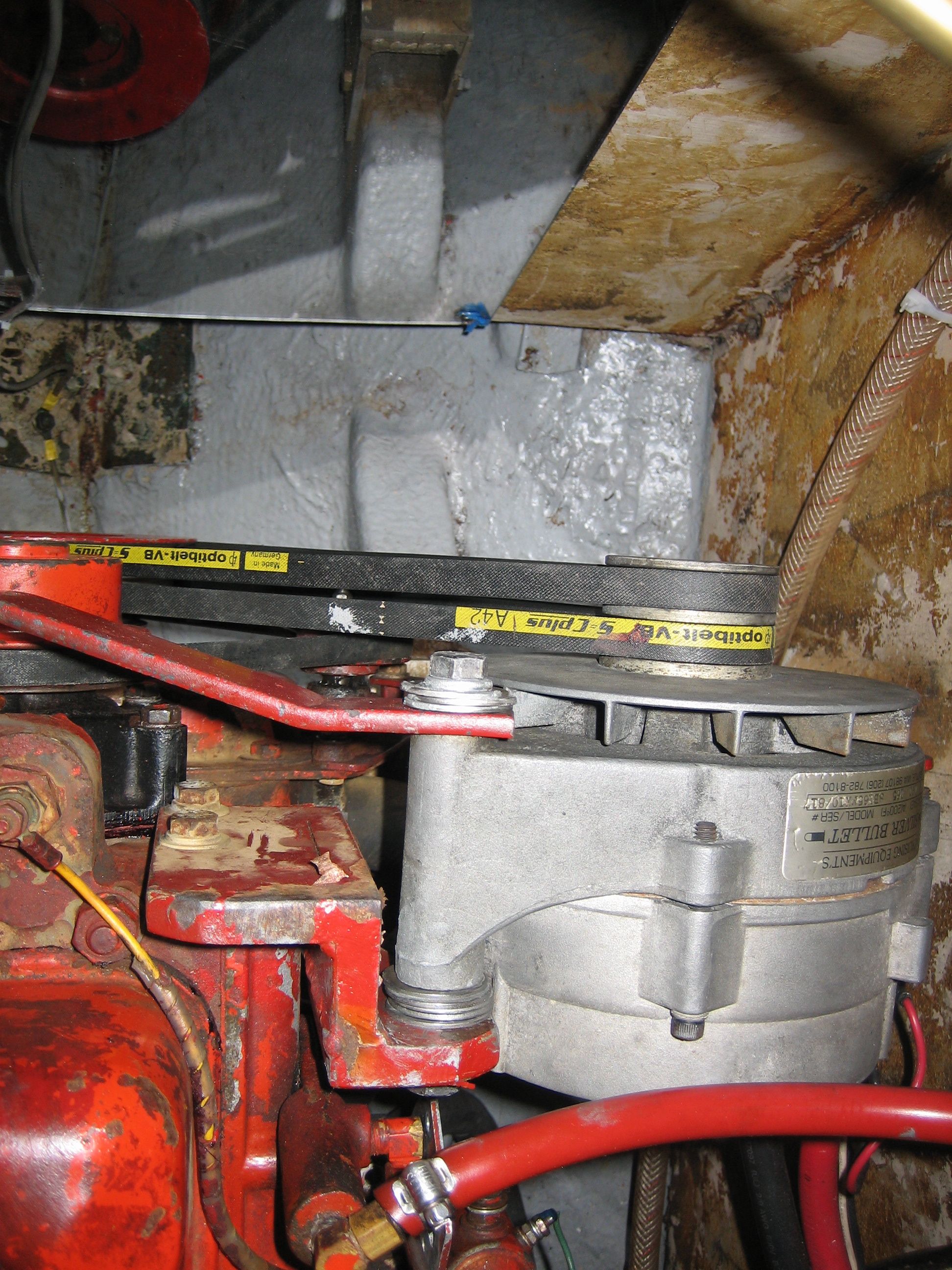
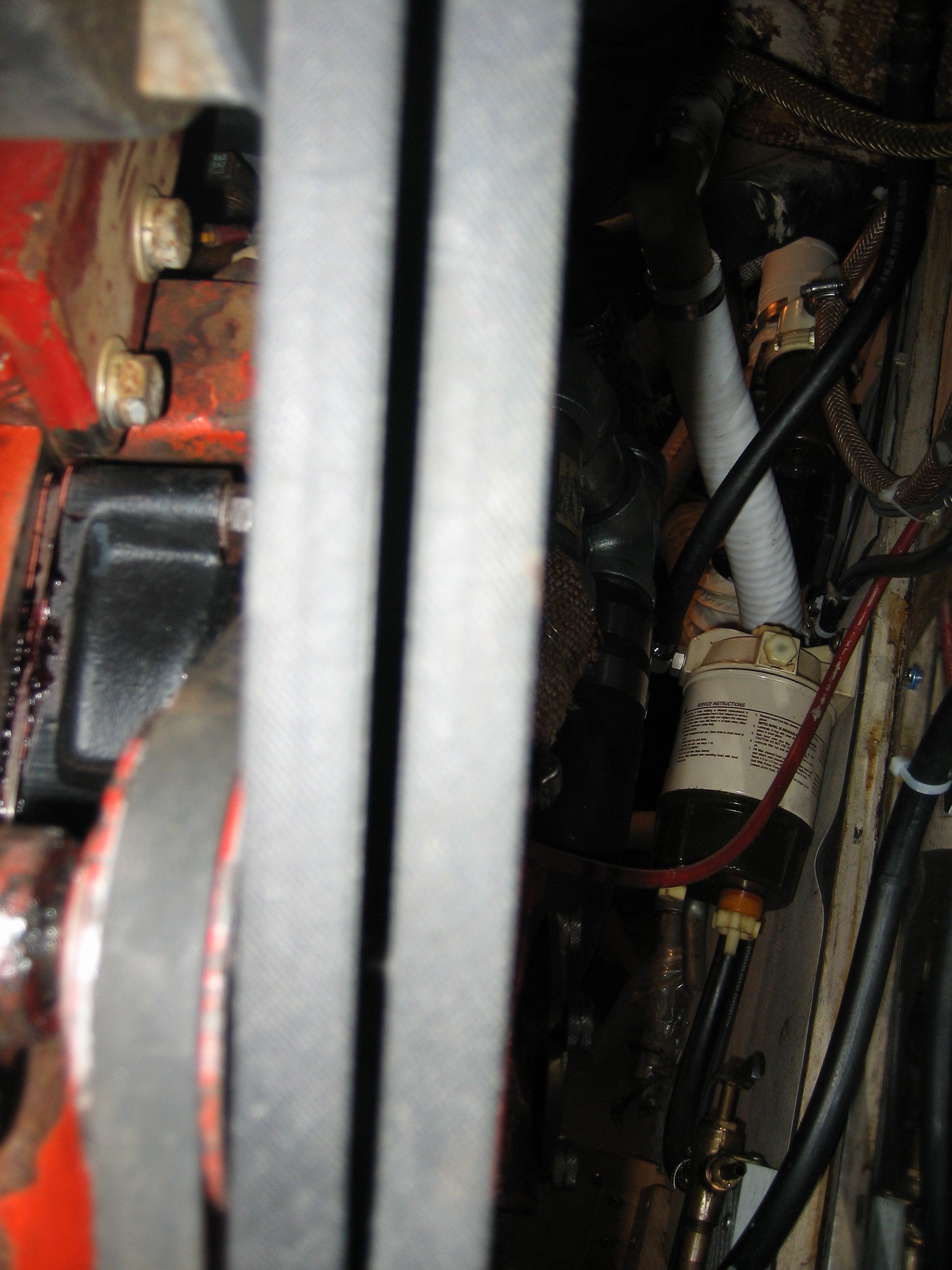
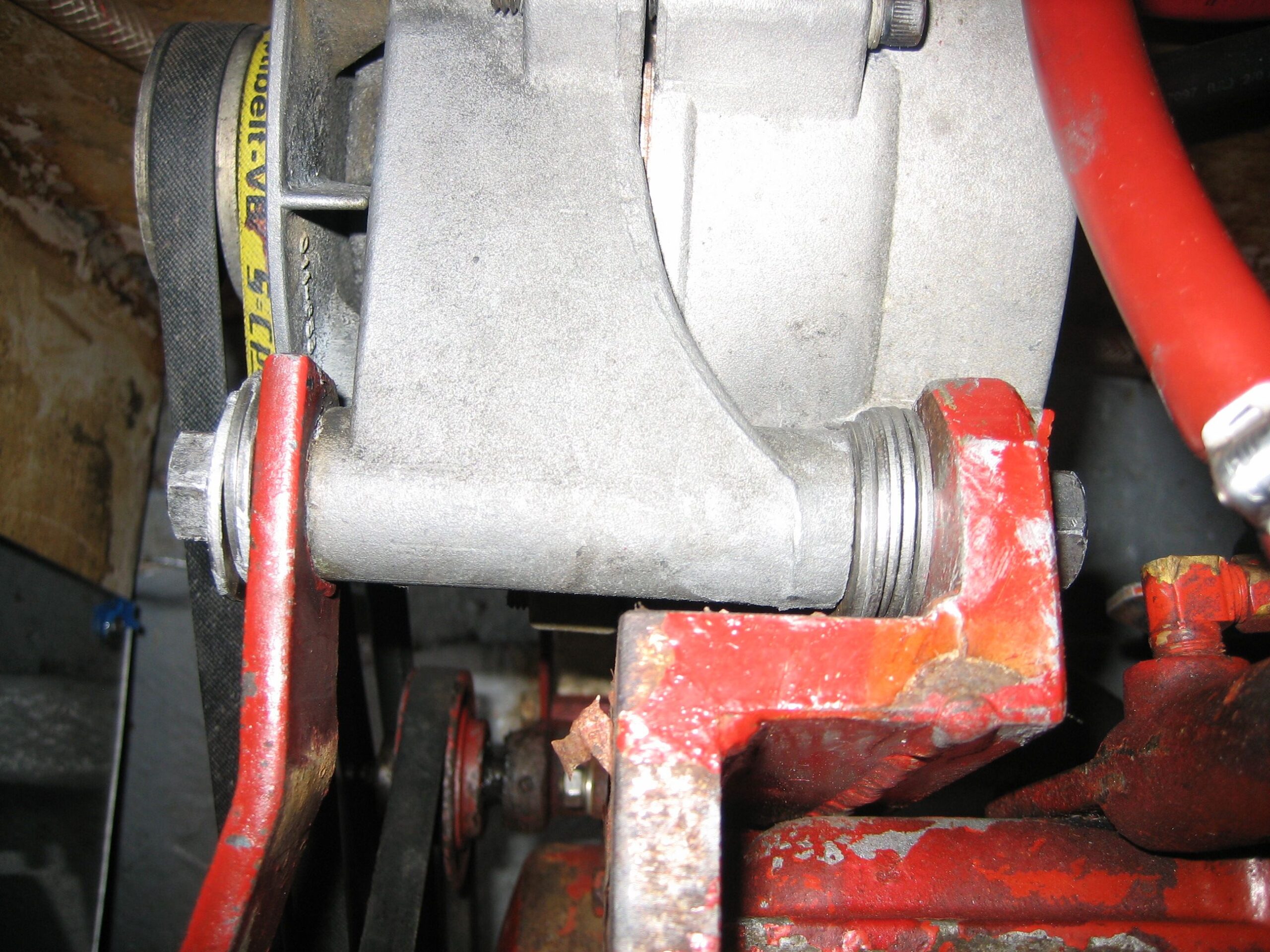
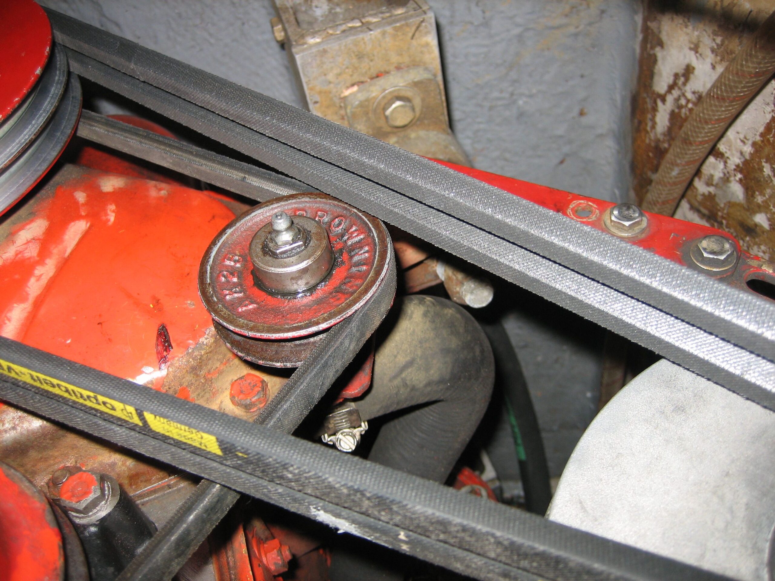
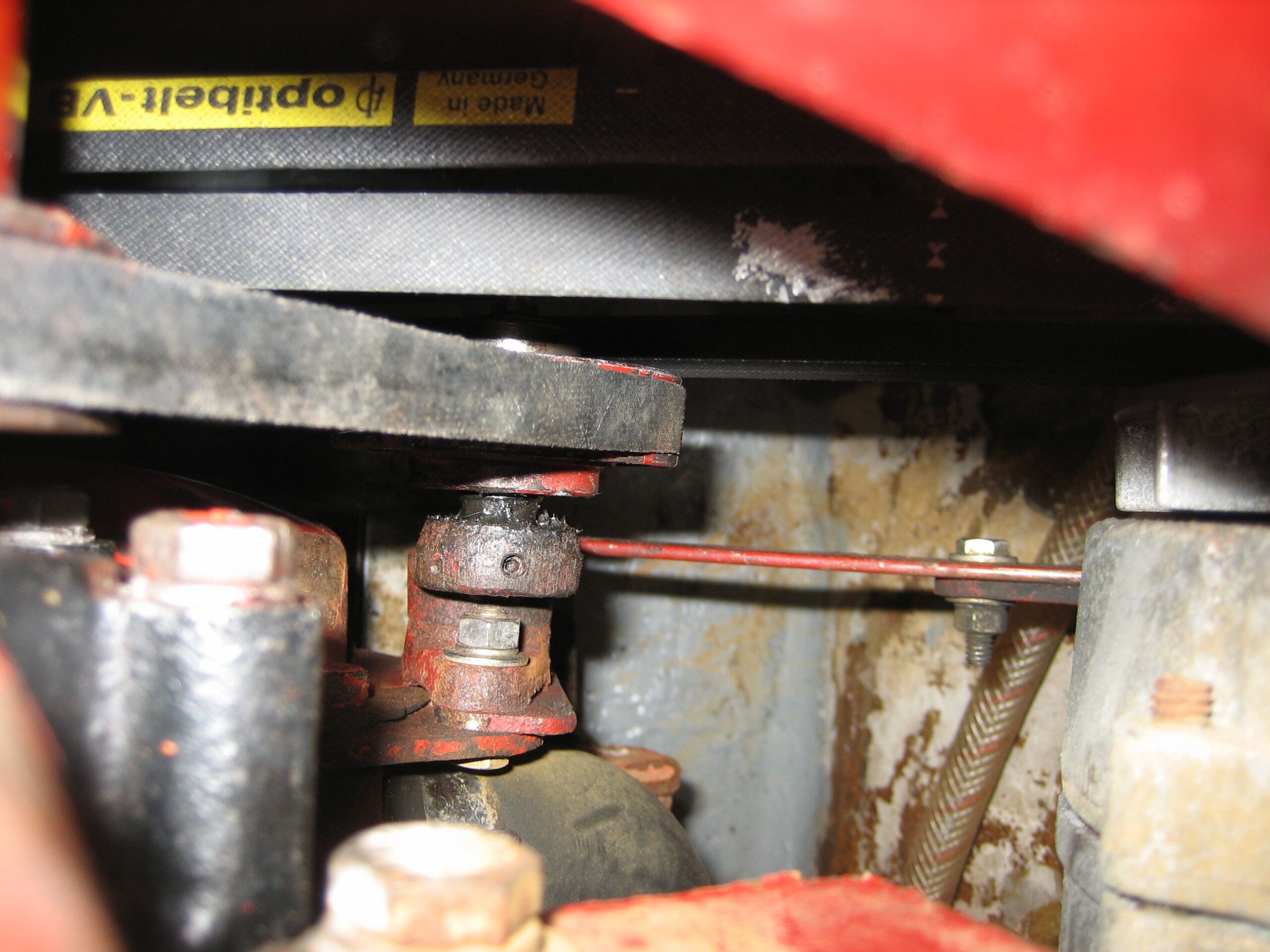
The problem: the alternator belt was rubbing on the idler pulley. This is a strange problem to have, because I never noticed it before, and we didn’t really change anything. Except that we replaced the water pump–so maybe the pulley on the new water pump wasn’t as close to the engine as it was on the old water pump? Then I started worrying that I hadn’t pressed the pulley far enough onto the pump–I recall it seeming like it was a millimeter farther on the old pump, and since this was the only thing we changed, I assumed this must be the problem.
So jonny pulled the pump off the engine again, and I took it down to the Tech Shop with me this time (last time I tediously managed to pull it off with a vice, but it was definitely the wrong way to do it, and now I have a tech shop membership anyway). I pressed the pulley farther on–too far in fact, it stopped being able to turn–then I used a puller to pull it off just enough so it would turn freely. So I am positive that I have the pulley as far on the pump as it will go. I gained MAYBE a millimeter out of it.
Then we had to laboriously scrape and clean off all the old gasket material (well secured with permatex!), buy new gaskets, and reinstall the pump.
After doing all that, the belts still rubbed. So then I took off the alternator and added a couple of washers to shim it farther out, and then finally the problem was solved. I don’t believe that I messed up the belt alignment through my actions; if anything, it looks like the alternator belts line up better with the added shims (though it is extremely difficult to tell by eyeballing it).
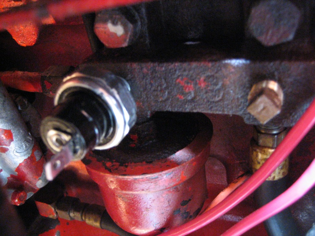
One of the terminals on the oil pressure switch that triggers the low pressure alarm broke off. The oil switch is mounted to a little manifold; also mounted to this manifold was a foot long hose that served no purpose. I took it off and capped the hole with a bronze stopper (before I did, I called Sherri at Transatlantic Diesel to double check–too often we take something off that we don’t understand only to later realize that there was a good reason for it).
(image shows new switch without wires attached; bronze square headed plug is to the right)
For two months we have had a frustrating diesel leak, just enough to cause the engine to lose its prime after sitting for a day. We can start it back up right away after running it, no problem. But wait a day, and we had to bleed the system again.
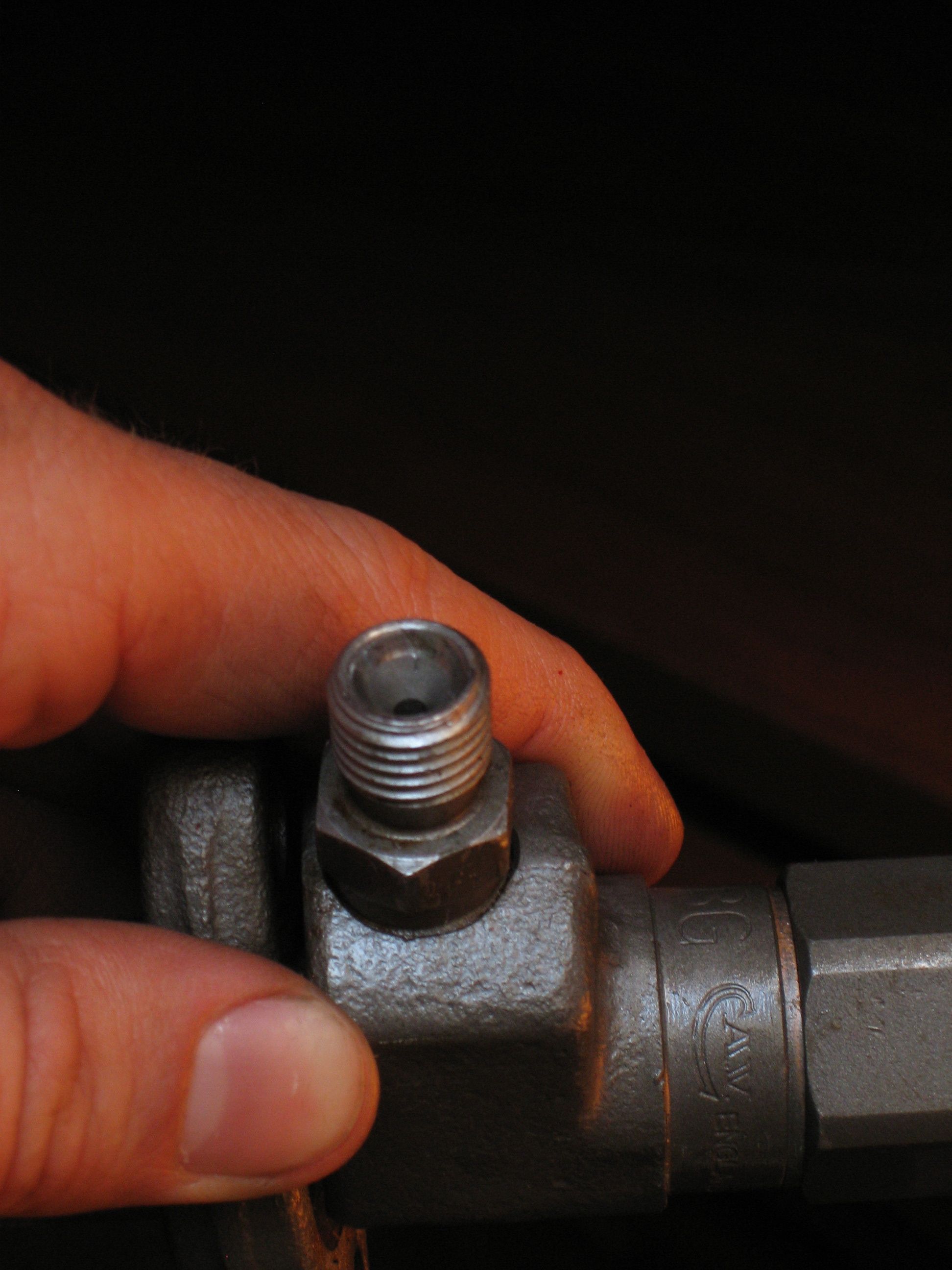
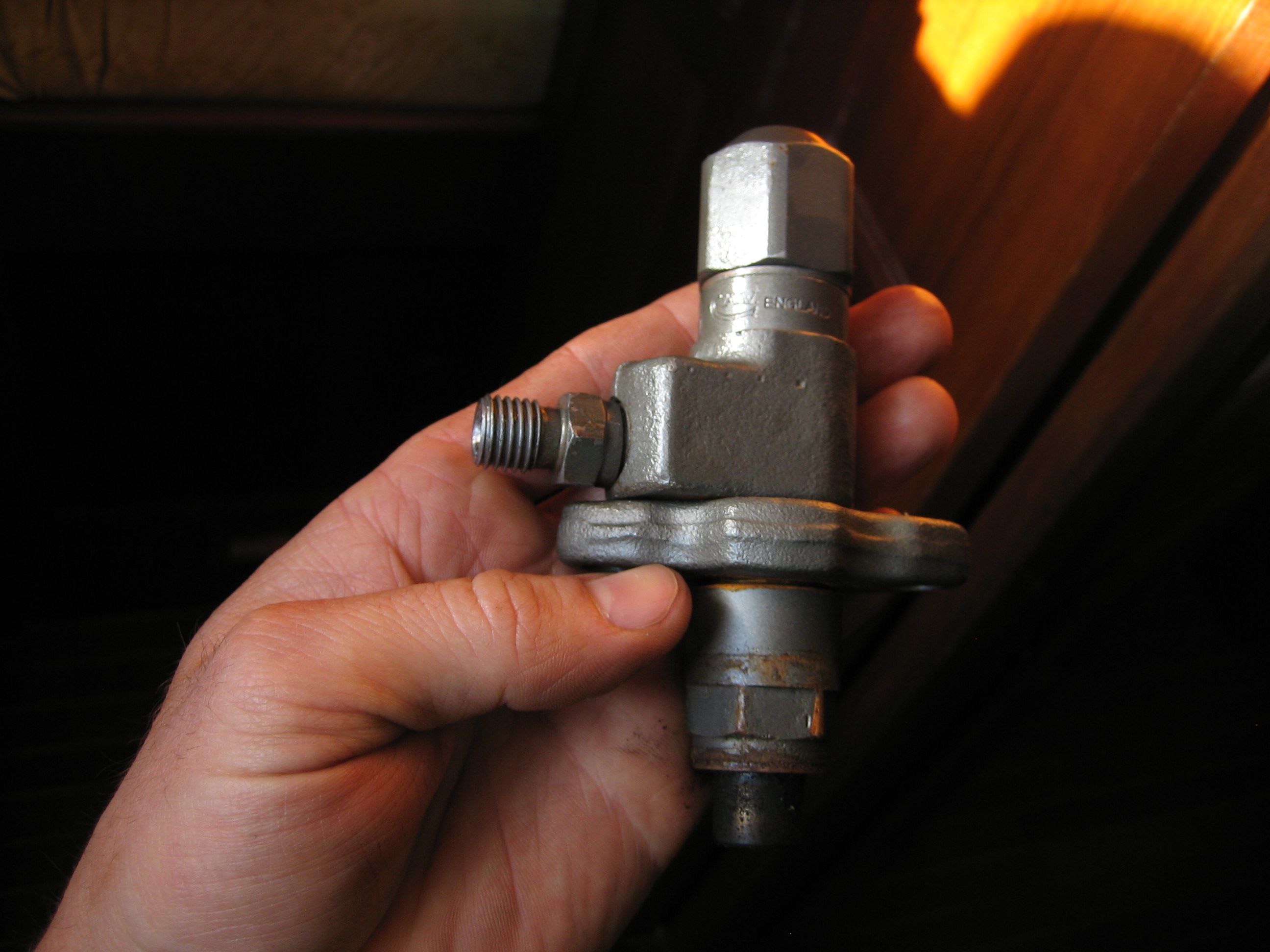
Pete thought that the fuel switch located on the injector pump was leaking, so Jon replaced that. Didn’t fix the problem, though I think it was part of the problem.
An injector started leaking from around the nut on the feed line. I discovered a tiny scratch on the surface of the nipple of the injector, undoubtedly created by some errant shard of metal when we put the injectors back in. I removed the injector and took it to Diamond Diesel in Oakland and they replaced the piece for free (I had them all rebuilt just a few months ago). This was definitely part of the problem, but it still didn’t fix our priming issue.
I decided that the fuel manifold to which the fuel switch is mounted was leaking, because it didn’t have a copper washer to seal it properly (no idea why). Took it off and added a copper washer. Leaking stopped, engine doesn’t lose its prime now.
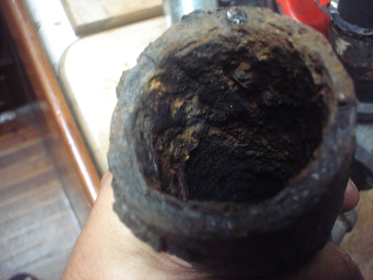
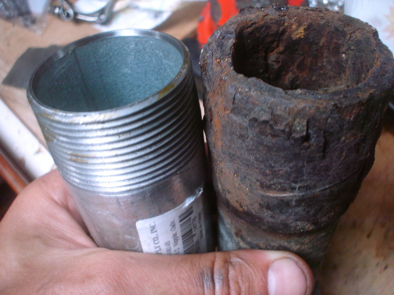
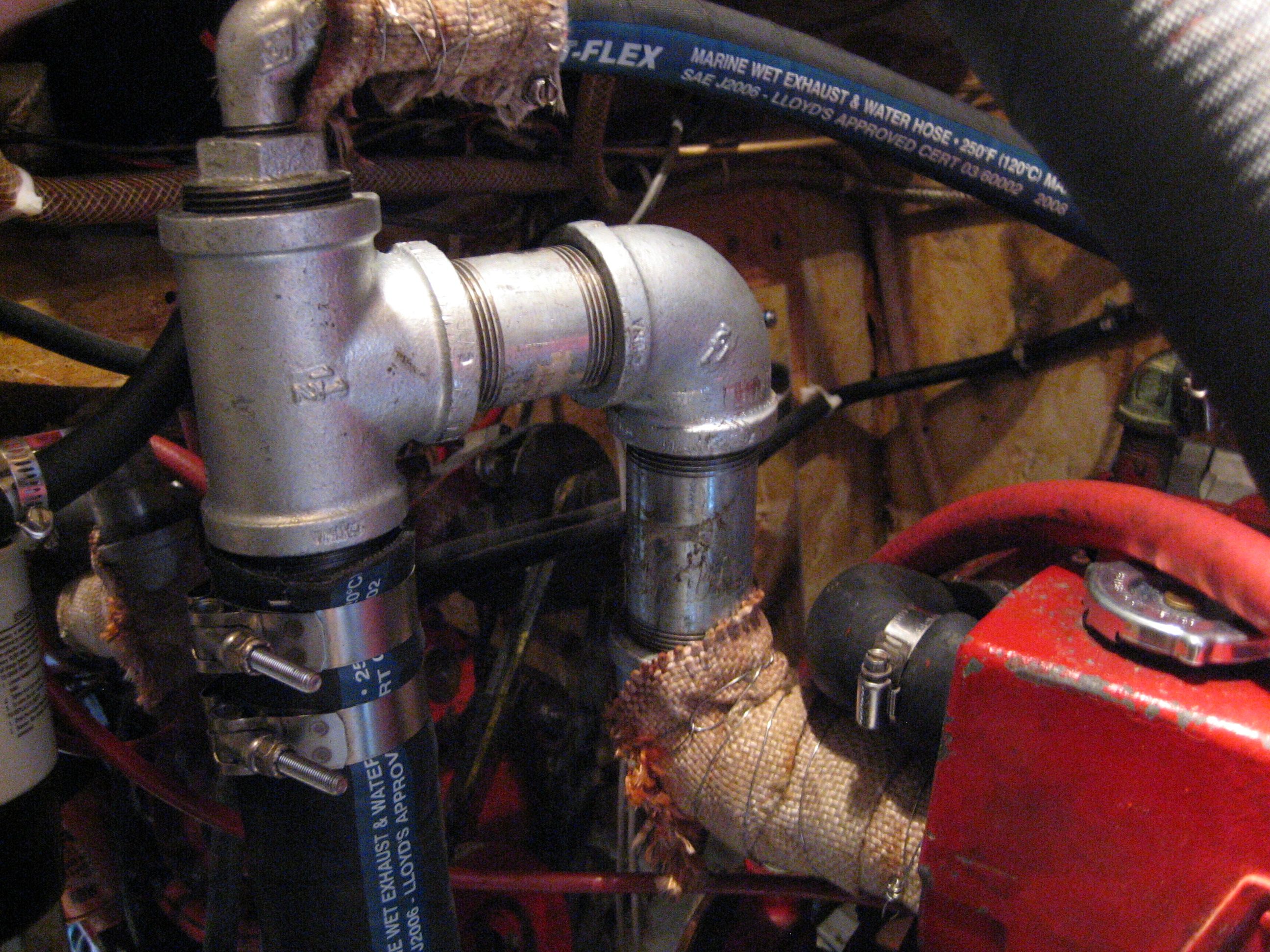
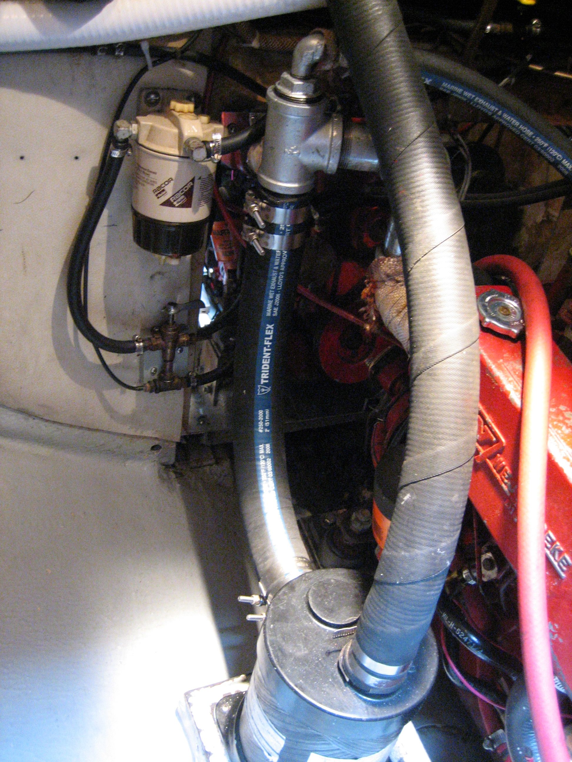
The engine has been overheating when pushed hard, so I was thinking that it was a reduced cooling capacity rather than an outright problem. I started by replacing the seawater hoses from the through-hull to the strainer and strainer to the v-drive. Jon replaced the hose from the pump to the heat exchanger, I replaced the hoses from the heat exchanger to the anti-siphon fitting and anti-siphon fitting to the exaust elbow. Jon soaked the heat exchanger, oil cooler, and transmission oil cooler in muriatic acid. I replaced the impeller when I added the speedseal cover. I soaked the anti-siphon fitting in muriatic acid. There was no way of telling how corroded the exhaust fittings were without taking them apart. In order to take it apart we had to cut it off with the grinder, so then we had to replace it regardless of the condition. I pieced together all the necessary fittings out of galvanized steel from a great hardware store over in Alameda called Pagano’s (it’s close to Svendsens, so convenient). One of the guys at Svendsen’s warned me that it might kill us to use galvanized (as opposed to bronze or stainless), and I know that the galvanized coating is dangerous when it gets hot enough to burn off, but a) I doubt it gets hot enough b) the previous fittings were galvanized c) I’m not paying $300 for bronze fittings for our exhaust elbow. We can’t afford to be cancer free!
Our engine overheats after we run it for a while (not right away), indicating reduced (not absent) cooling capacity. The sea water strainer is clean, we scrubbed the bottom to make sure the strainer mounted over the through-hull is clear, and replaced the impeller. The next step for us is to replace clogged hoses and clean the transmission oil cooler, engine oil cooler, and heat exchanger. I purchased muriatic acid at a local hardware store and jon did the deed of removing the heat exchanger, flushing with water, then soaking in acid, and flushing with water. He could tell that it made a difference just by looking at it. He is currently working on the hoses and other elements, so I can’t report on the result yet.
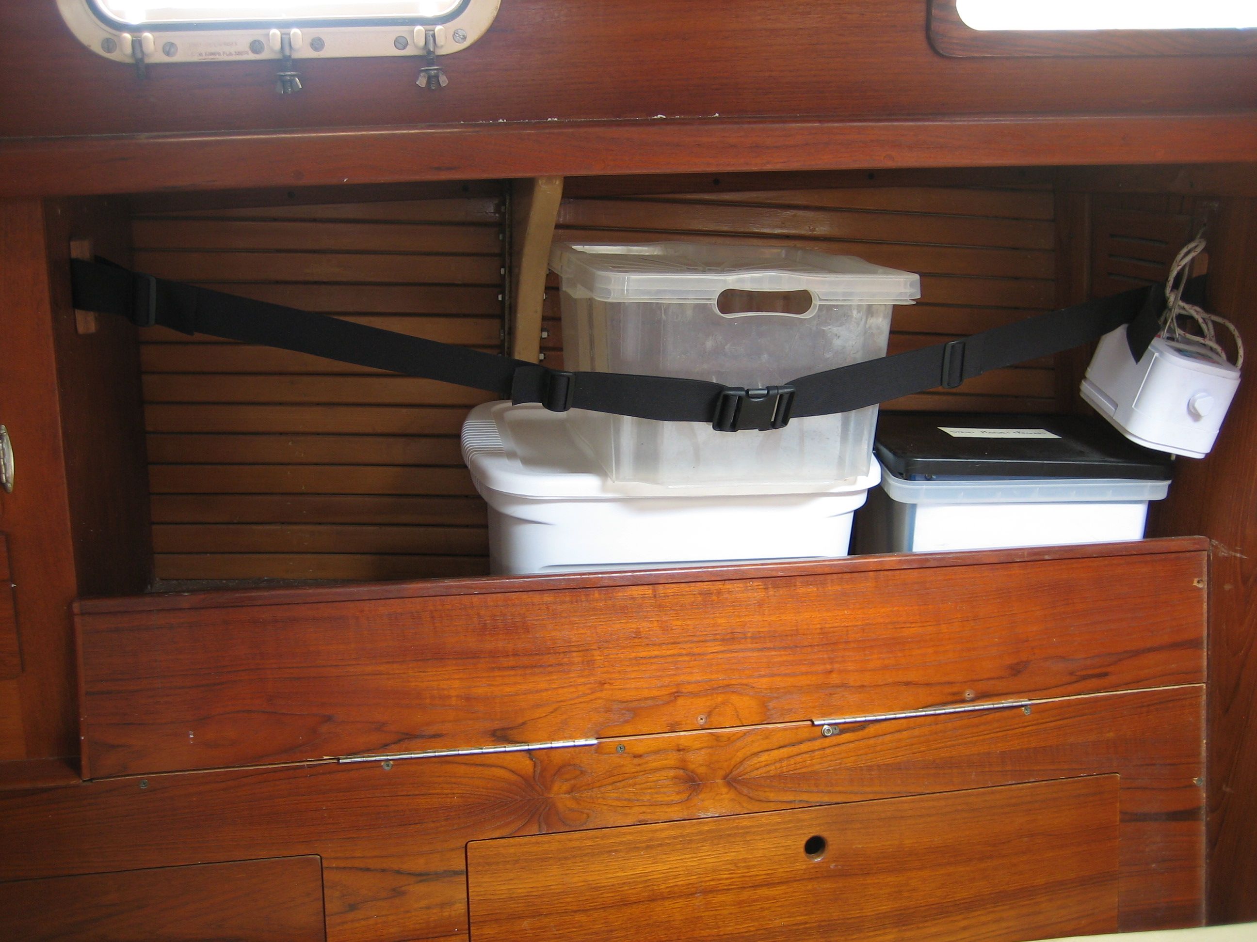
On the starboard side, the back of the port settee forms a short retaining wall in front of the bottom row of books, and this piece is hinged to fold down in order to access the books. The port side was not constructed this way, and we have spent the past year being annoyed whenever we try to pull our bins in and out of that storage spot. So jonny took the jig saw to it and used our remaining two sections of hinge scavenged from the old table to hinge it. A barrel latch will be installed on each end to secure it. Eventually I think we will build some shelves up in that space to better utilize it.
notice barrel latch on bottom left corner
we used piano hinges scrounged from dismantling old table
This was a problem of our own making. First we painted the bilge, including the edges against which the cabin sole board edges rest, which reduced the clearance enough to make it difficult to get the boards in and out. Then we sanded the edges down to make them fit. Then the raw wood on the edges, which we didn’t treat with anything, absorbed water and swelled, making it even harder to get them in and out.
Finally yesterday, using our latest fantastic new tool toy (Ryobi 3×21 belt sander–flat topped so you can flip it upside down and use it as a grinder) we sanded down the edges properly, and also the bottoms while we were at it, and coated all of those surfaces with penetrating epoxy. (we used Smiths Penetrating Epoxy, purchased at our local chandlery Svendsens in Alameda–for those who don’t know, the penetrating epoxy is as far as I can tell just epoxy extremely thinned down with volatile solvents, so that it is thin enough to soak into things, the solvent evaporates off and the epoxy cures over the course of a day or so).
Eventually, we will add latches to these boards so they won’t fall out when we’re upside down.
It is unforgiveable that I didn’t do this long ago–all it would have taken would be to drop a wrench onto the batteries just once and some really bad shit would have gone down–and I’m constantly working with screwdrivers and wrenches over the batteries.
I made covers out of an extra sheet of 3/8″ clear acrylic that we had. I cut out the pieces of acrylic with the cutoff blade on the grinder, and it is DEFINITELY the best way to do it among the tools we have. I’ve tried using the jig saw and the fein tool, and both are annoying and inferior. I glued a few tabs around the edges to seat the cover on properly with methylene chloride–TAP plastics sells it for just this purpose.
It is a convenient feature for the covers to be clear so we can what’s going on with the batteries. Also, the covers now form a great table for placing tools while working in the engine room :-).
The covers remain unfinished–I stopped messing with them when I realized that when we put the new batteries in they will need to be modified.
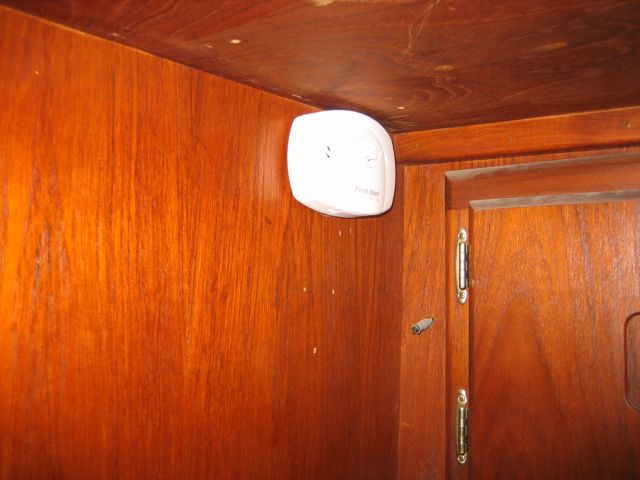
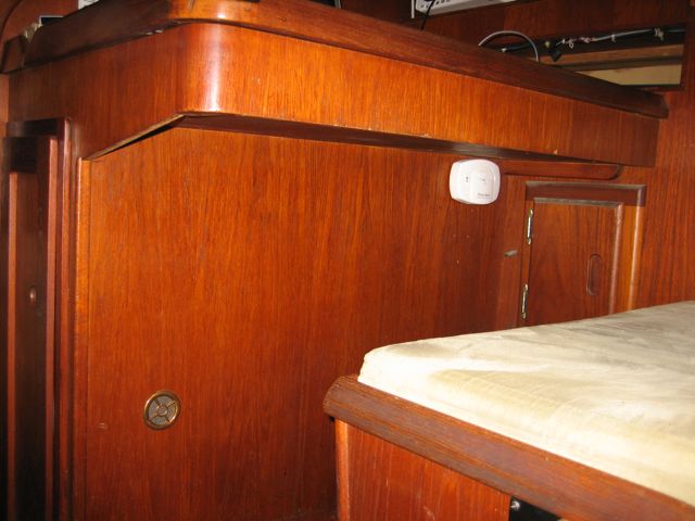
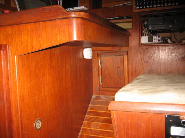
Due diligence. Found a battery (2 AAs) operated one for $20 from Ace hardware. Jonny mounted it up underneath the nav table in the corner where our knees don’t reach. We briefly looked into whether CO rises or falls–mount at the ceiling or floor–and discovered that it is the same density, so it will rise if it’s hotter, fall if it’s cooler, so it doesn’t matter where you mount the detector. We chose to mount it under the nav table, up in the corner.
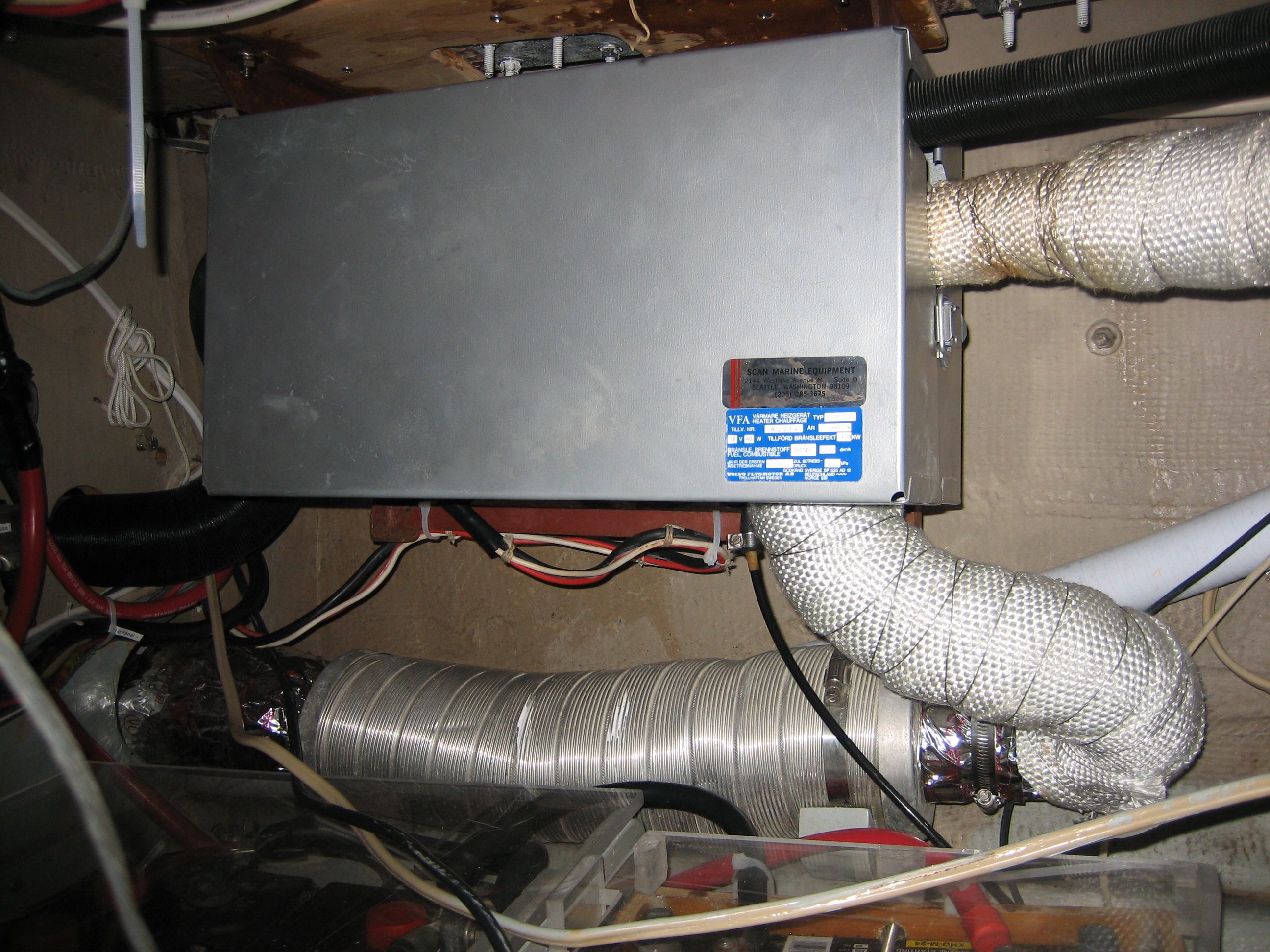
I had already remounted the furnace outboard and forward of its old spot a few extra inches to gain us additional space in the engine room (this happened while it already was removed to access the jib car track and stanchions to rebed them). While I was at it, I partially dismantled the furnace, satisfying myself that it was in pristine condition (how rare!) and needed no immediate attention from me.
Some short lengths of ductwork were missing: the piece through the wet locker and the piece underneath the nav seat. I replaced the one in the wet locker with the common, expanding type available at home depot. I wasn’t excited about the durability of it, but I wrapped it with a ton of foam insulation and then taped it all over with the metal duct tape to strengthen it. The section underneath the seat had to be stronger (tools get dumped on it) so I found a double wall scrap piece from Urban Ore down the street from us (a great source for obtaining other people’s garbage). The fitting that joined the duct to the vent was missing, so I fabricated one out of a section of single wall metal duct that was flexible enough to bend into the shape I wanted with pliers (and extensive shaping with the cutoff blade).
The section through the wet locker still gets too hot to touch and scares me, but I don’t think it’s dangerous. I wrapped the entire exhaust section with fiberglass tape designed for the purpose (previously just the last two feet were wrapped with it) and secured it with stainless seizing wire so it wouldn’t work loose.
The last thing I have to do is install a tiny little fuel filter in the fuel line–I found one that is meant for this purpose in the spares bin and I think it’s a good idea. Not to mention I’d rather store it in usage in the fuel line than in a bucket in our locker.
exhaust ducting that exists aft, to starboard of cockpit


")


")