The old one had rotted away. We replaced it with epoxy saturated (Smith’s Pentrating Epoxy) marine grade plywood. Instead of screwing it to the fiberglass in the bilge, I through-bolted it.
Author: admin
-
Rebuilt bilge pump mounting plate (beneath cabin sole)
-
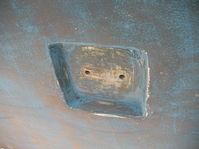
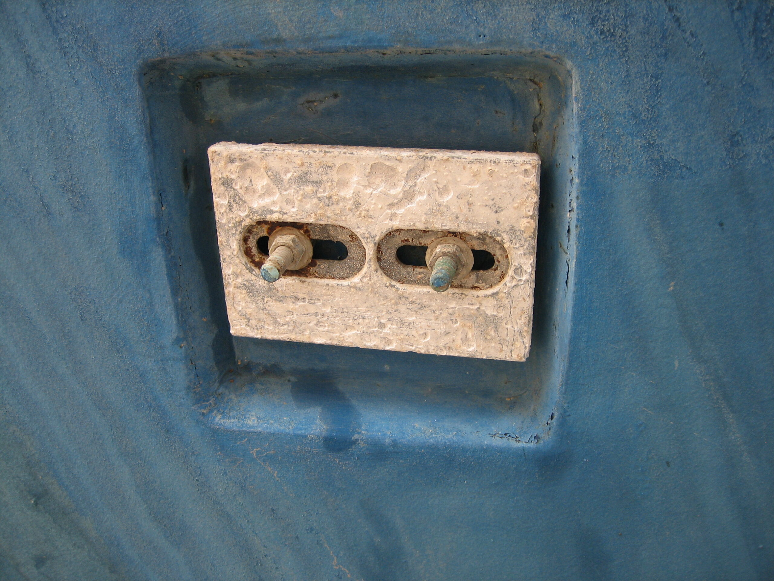
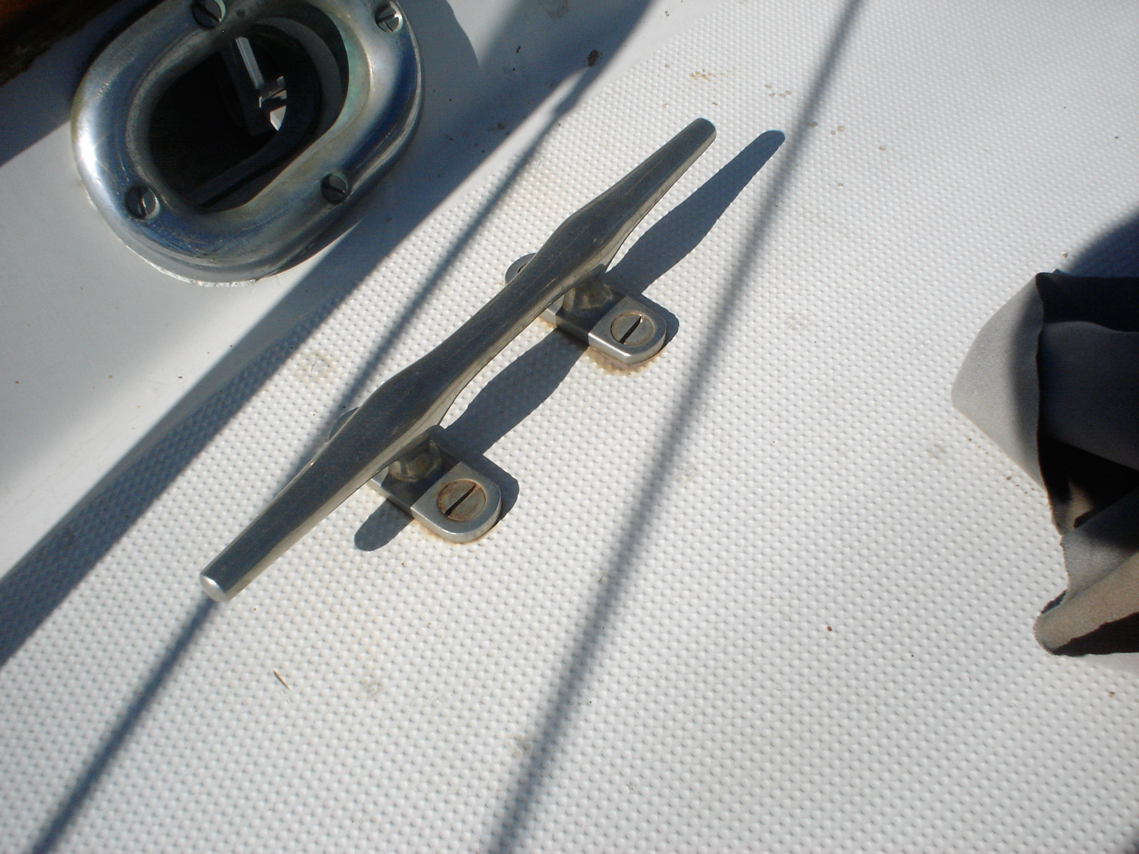
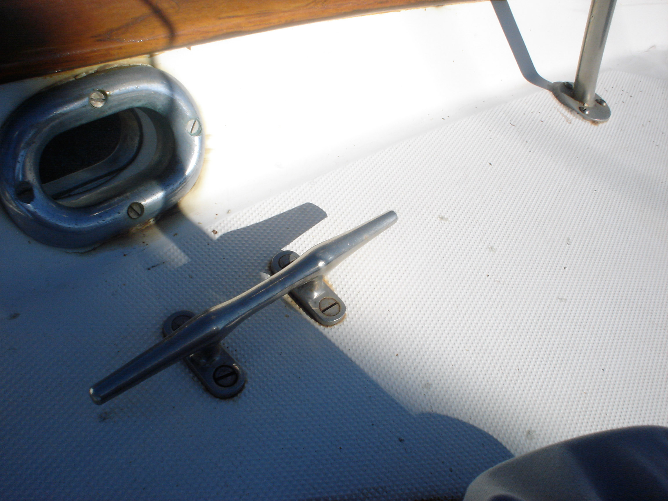
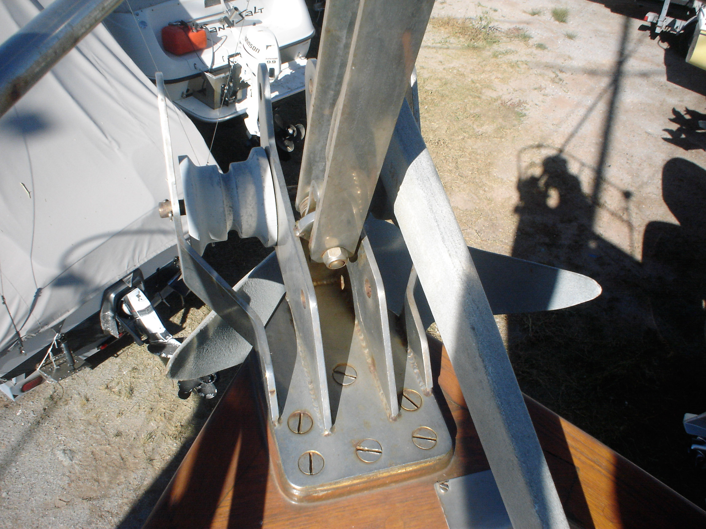
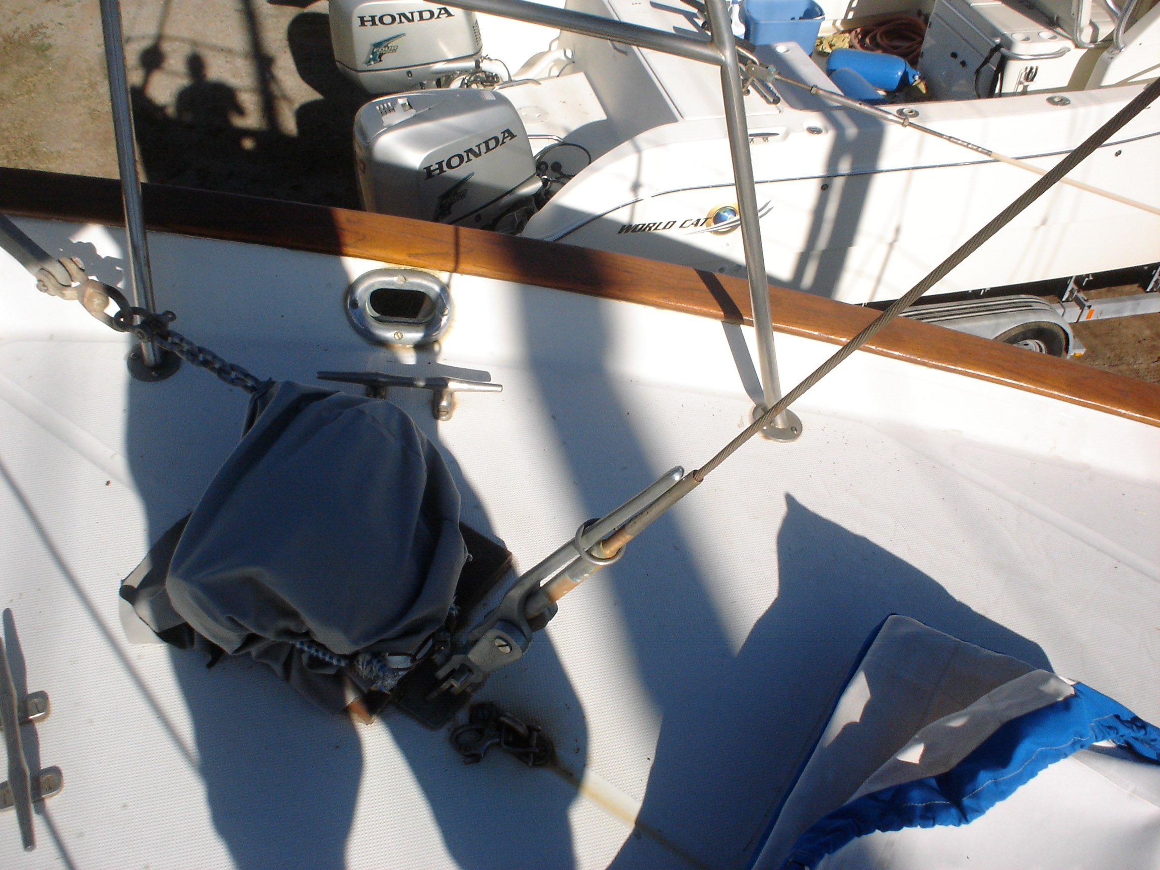
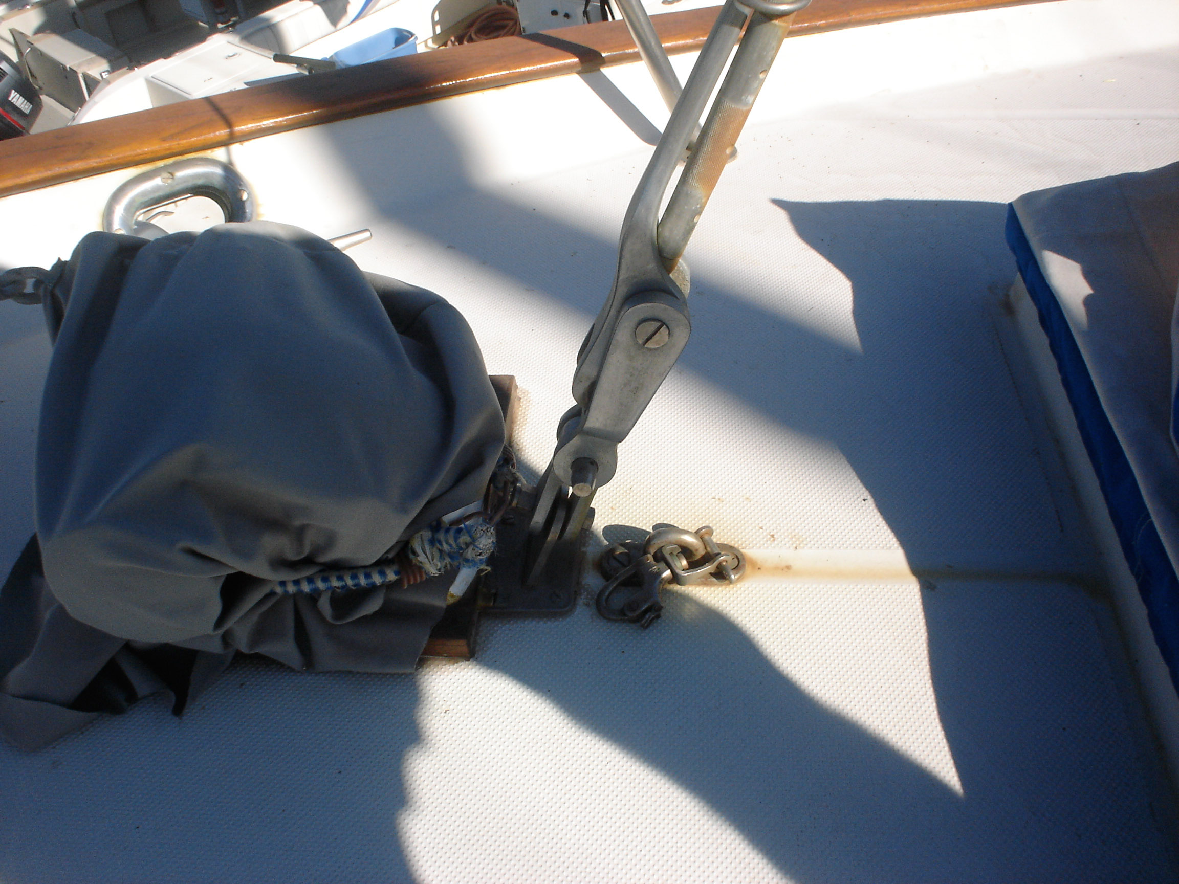
Replaced bow pulpit backing plates
When we had it trucked up from Mexico we removed the bow pulpit for 14′ clearance. In doing so, we discovered that the stainless bolts were inextricably locked to the aluminum (?) backing plates (which were 50% gone from corrosion, especially the ones in the anchor locker). So we ground off the heads of the bolts on deck, leaving the issue for the Berkeley workyard.
Our excellent friend John Ryan made us up some replacement backing plates out of stainless. We put it back together with neversieze on the threads and lifecaulk as the bedding sealant. I’ve settled on lifecaulk–a polysulfide sealant–as my number one preference. I used to think that I would use 5200 on everything, until I started trying to take apart old stuff that was put in with 5200. Now I stick with the lifecaulk. And I have gone sort of crazy with the neversieze–everything we take apart is a chore, requiring pounding, heating, lots of penetrant, extractor bits, and half the time we still end up drilling it out and replacing it. With the neversieze, I expect you’ll be able to take it apart pretty effortlessly for decades. But I still hate the stuff. My dad uses it (and used to make me use it when I was growing up on the farm) all the time, and it’s messy as hell. It gets all over everything and it spreads infinitely and it only comes off with gojo. Hate the shit, but I find myself using it on everything.
-
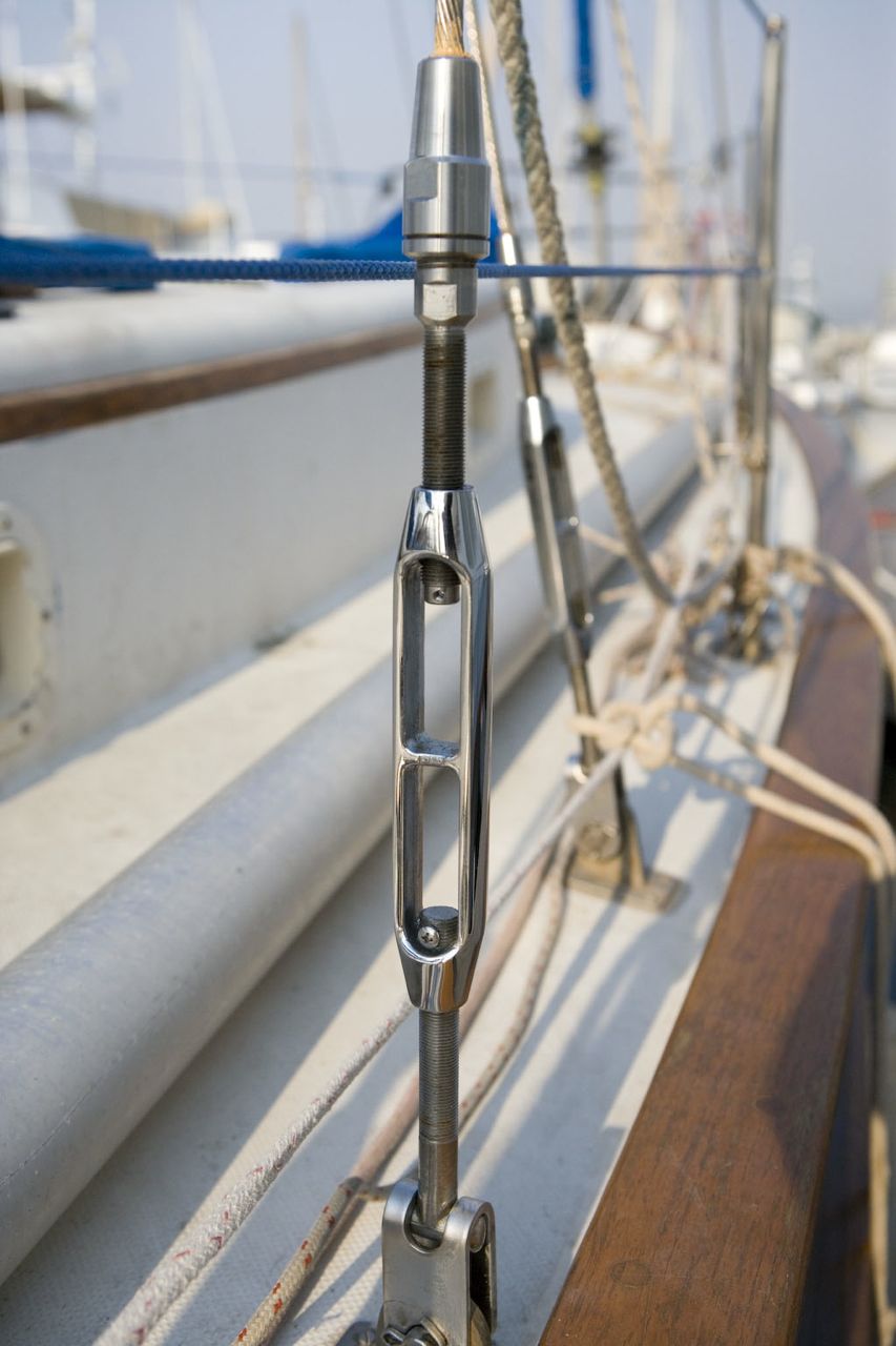
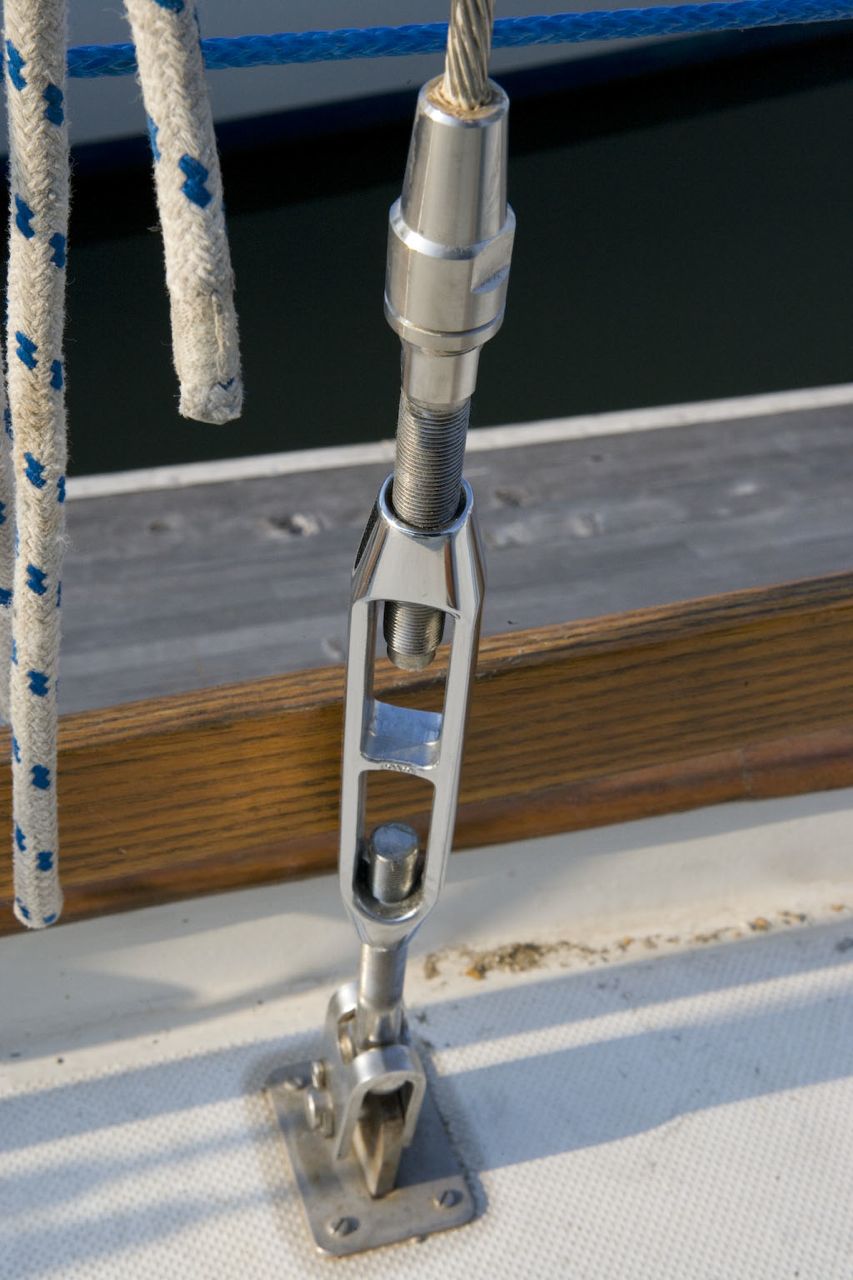
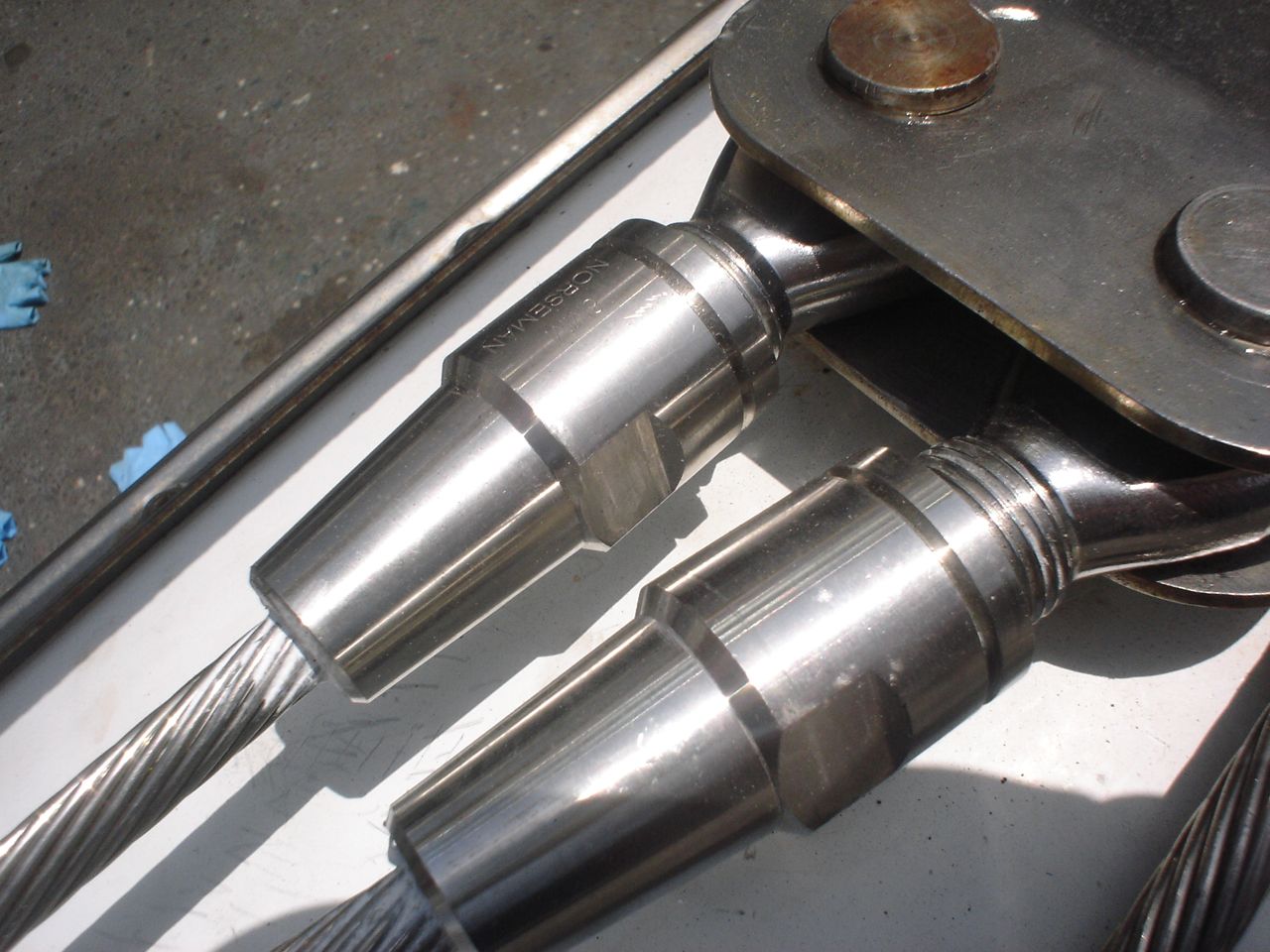
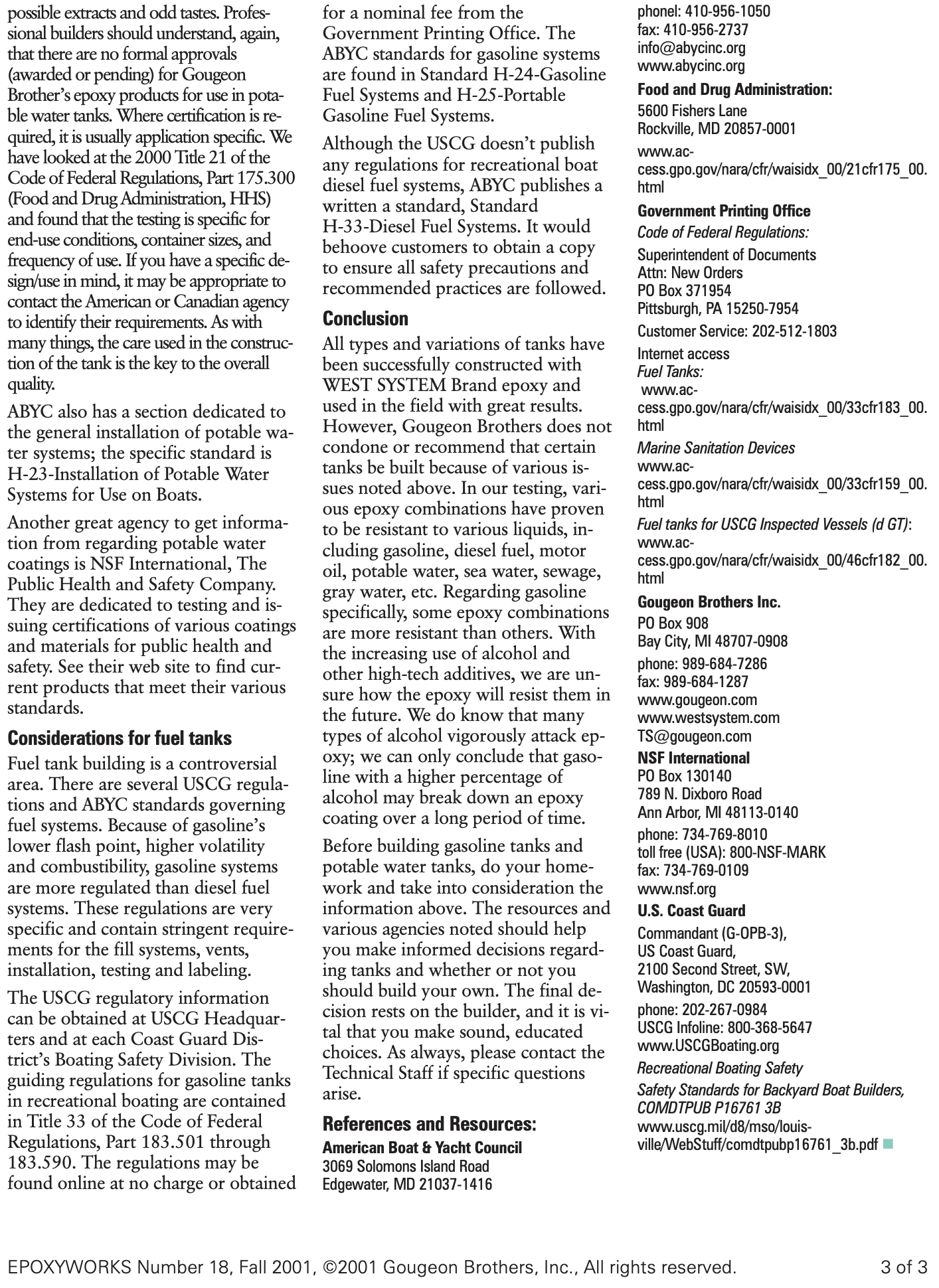
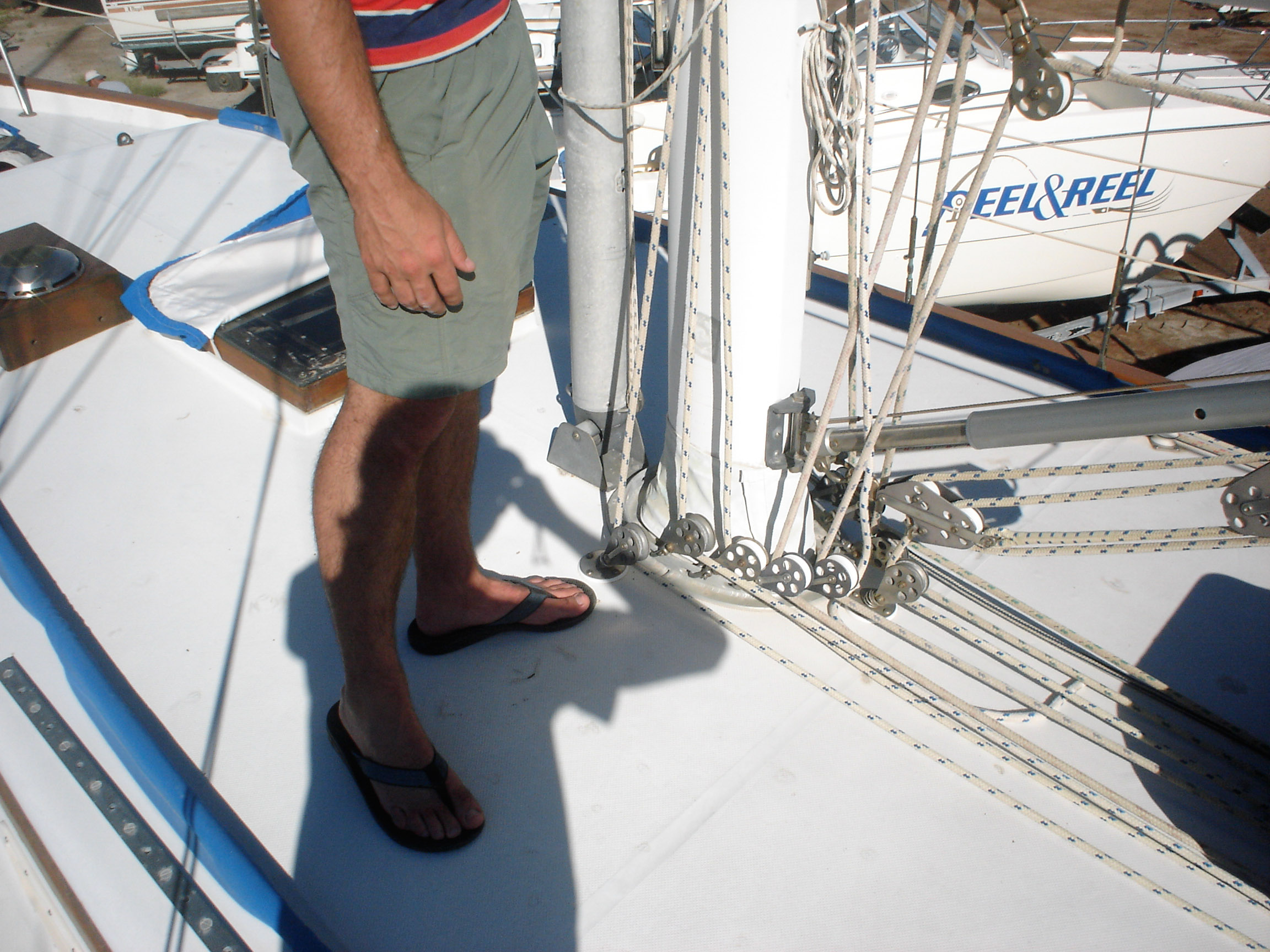
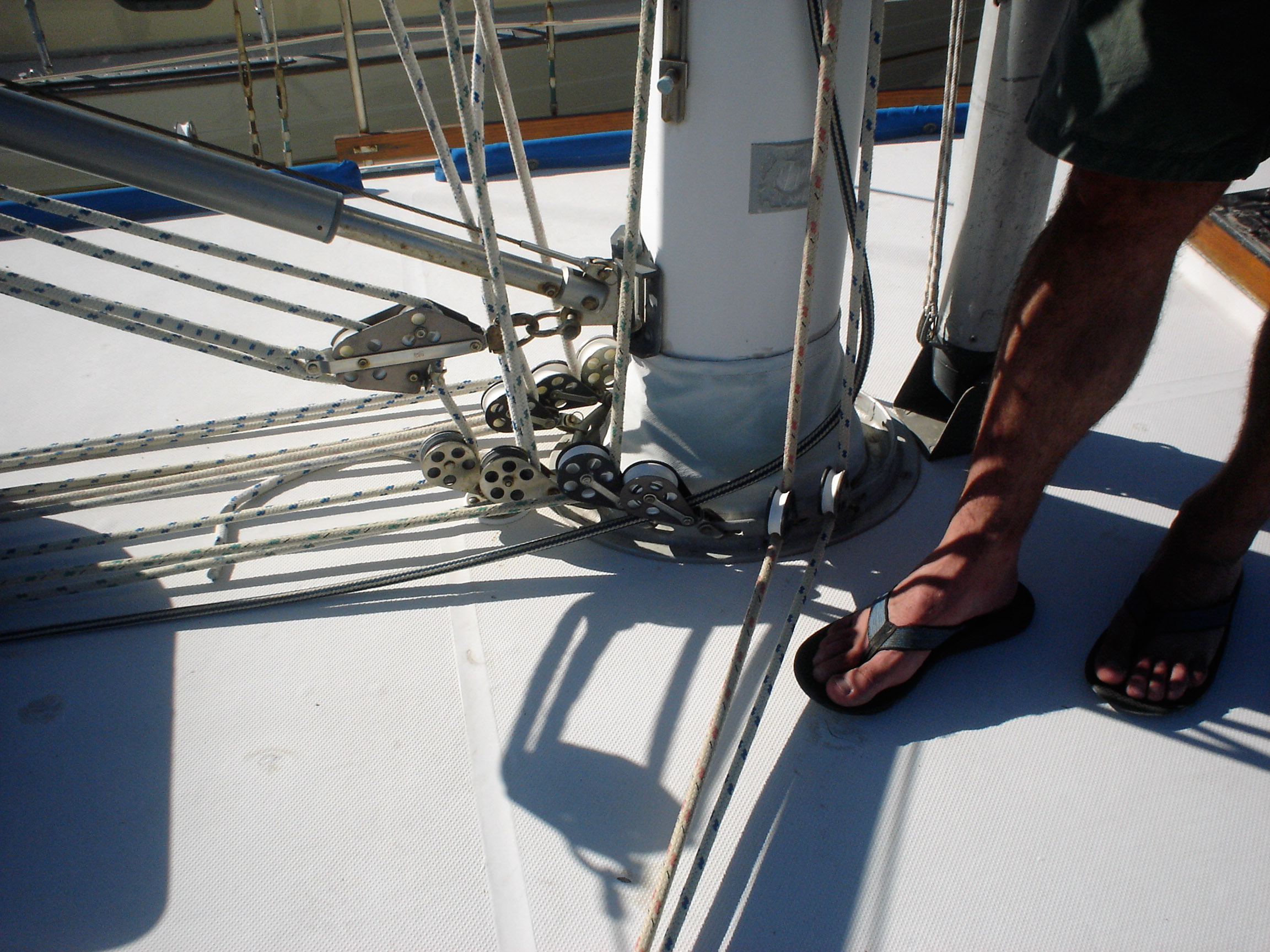
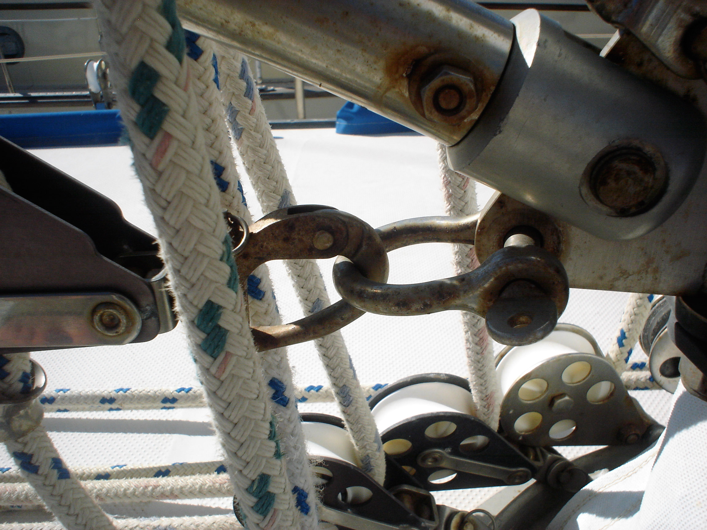
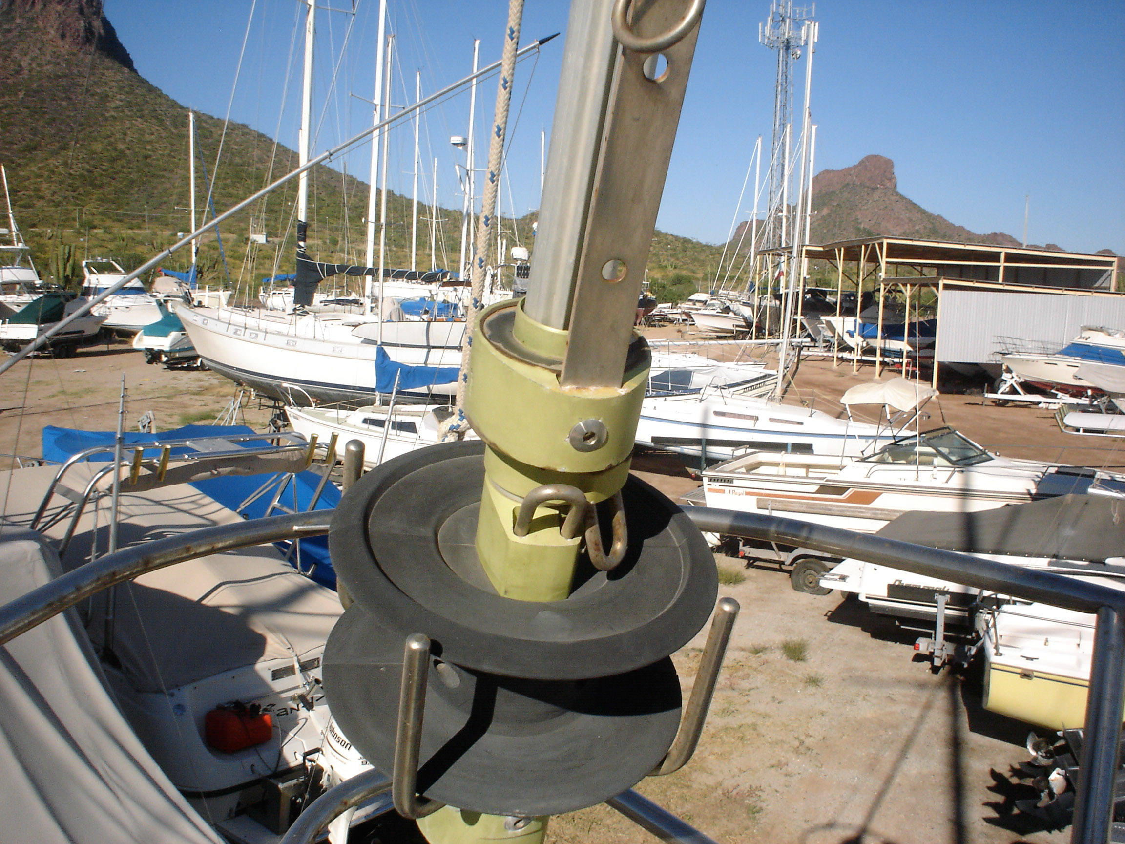
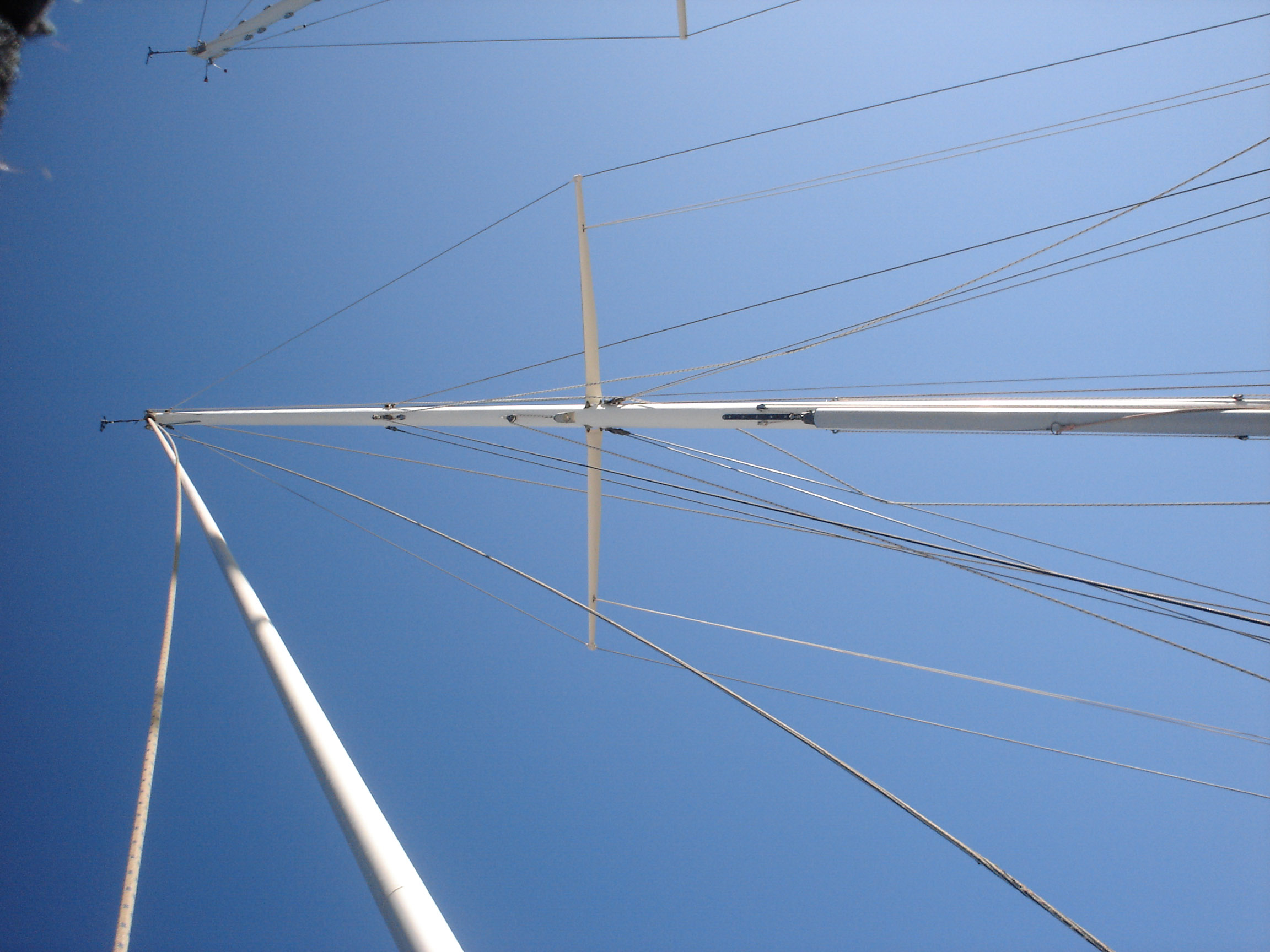
Replaced standing rigging
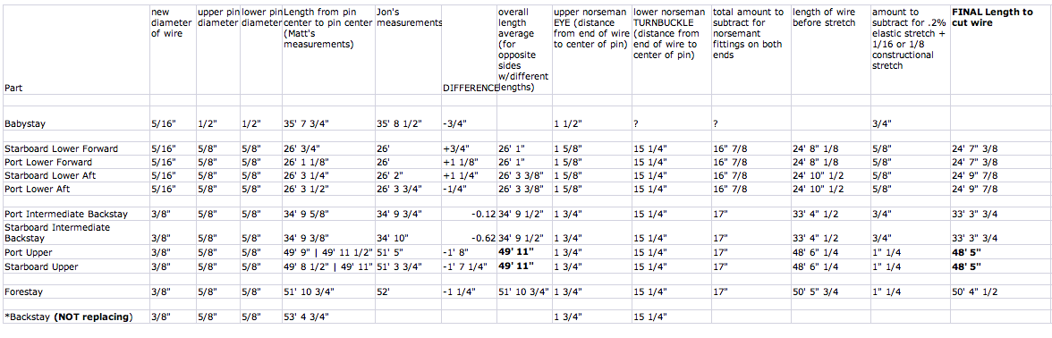
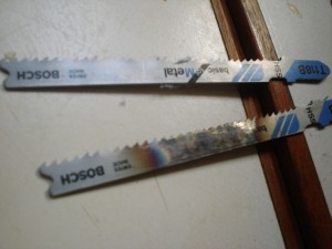
We redid everything except the backstay, which had been replaced in 2005 with a rod. The backstay was in great condition, and was already setup with the ssb insulators, so we felt it would be silly to replace a perfectly good rod. We used 316 stainless 1×19 wire, in two diameters: 3/8″ for the forestay and uppers, 5/16″ for the lowers, the babystay, and the intermediate backstays. We used norseman fittings, top and bottom, so that we could do everything ourselves. We measured from scratch, so to speak–from the hole in the tangs to the holes in the chainplate. Then we subtracted an amount for the upper terminal, the lower terminal, and the turnbuckle in order to determine what length to cut the wire. We cut the wire using a diamond blade on a dremel tool. This works just fine, but is slow. If you have a grinder, get a thin cutoff blade for it and use that (by the end we got around to doing it this way). We did all of this in the living room at our old place, 2,000 miles away from the boat, hoping that our measurements were all correct (we wanted to have it all ready to go when the boat arrived in the workyard, to minimize yard expenses). Here is our final spreadsheet of numbers. I decided on this plan using Brion Toss’s “Rigging Apprentice”. I used his numbers for constructional stretch as well. Like many do-it-yourself minded cruisers, we are much indebted to Toss for passing on his knowledge. When we restepped the mast, we discovered with delight that our measurements were spot on–each turnbuckle is now extended slightly more than halfway, which allows for some additional stretch and some tightening when we do a final tuning of the rig. Instead of using cotter pins to lock off the turnbuckles, we put a small machine screw through each hole with a nylok nut–it’s way faster to remove the nuts and pull out the machine screw than to bend the cotter pin back and pull it out–and the machine screws don’t cut and rip things like the cotter pins do.

-
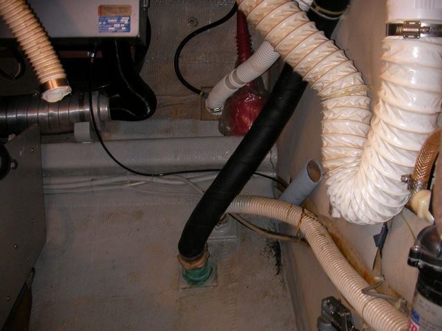
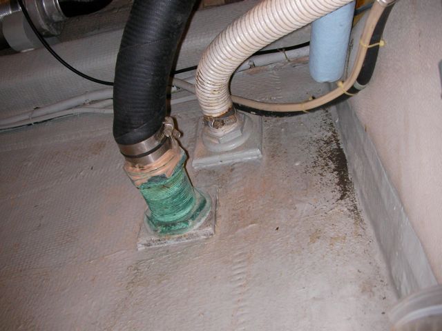
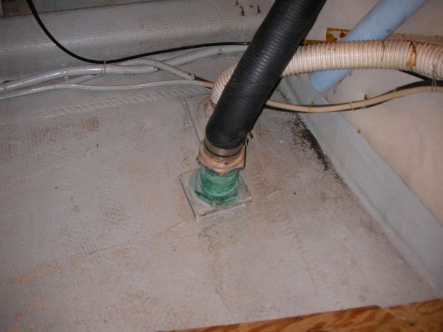
Redid underwater zinc installation
The old installation used two bolts through the hull; the head of the bolt was on the inside of the hull, lock washer and nut on the outside. The electrical terminal was under the head of the bolt inside the hull. This meant that the electrical terminals could not be removed, cleaned, or replaced without pulling the boat out of the water (which explains why the old terminal was rendered worthless by corrosion). Moreover, the bolts used were stainless, which is not very conductive. We purchased extra long silicon bronze bolts, cut off the heads of the bolts, and used doubled nuts with lock washers both on the inside and outside of the hull. This way the terminal can be accessed and replaced without affecting the zinc installation.
SANYO DIGITAL CAMERASANYO DIGITAL CAMERASANYO DIGITAL CAMERA -
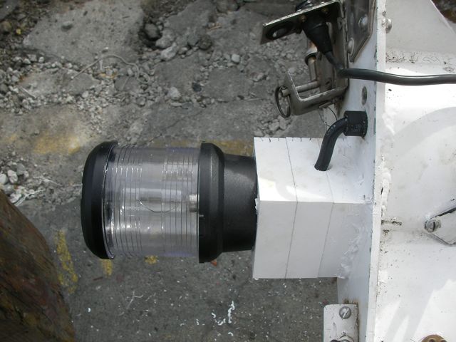
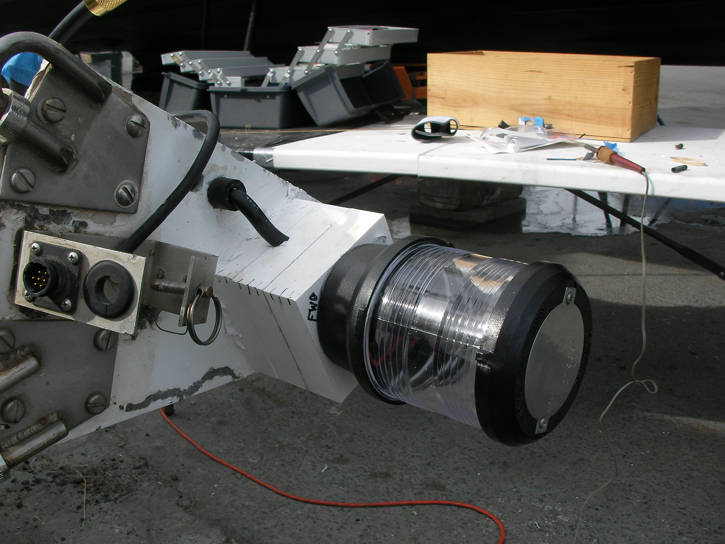
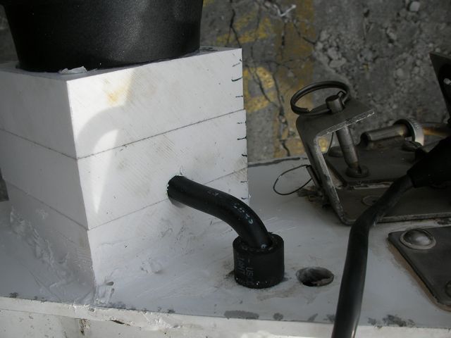
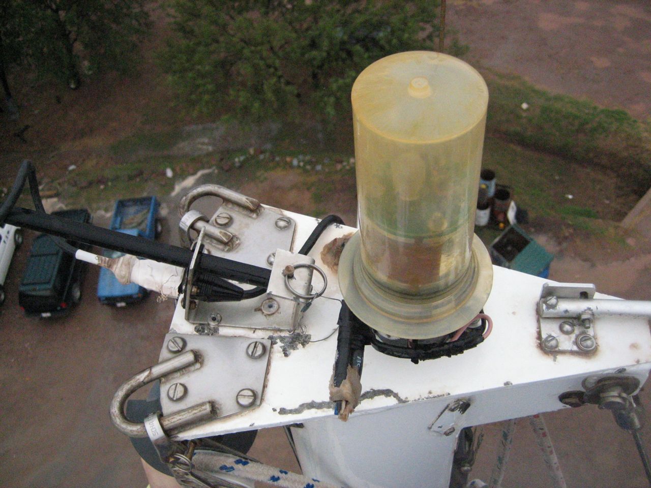
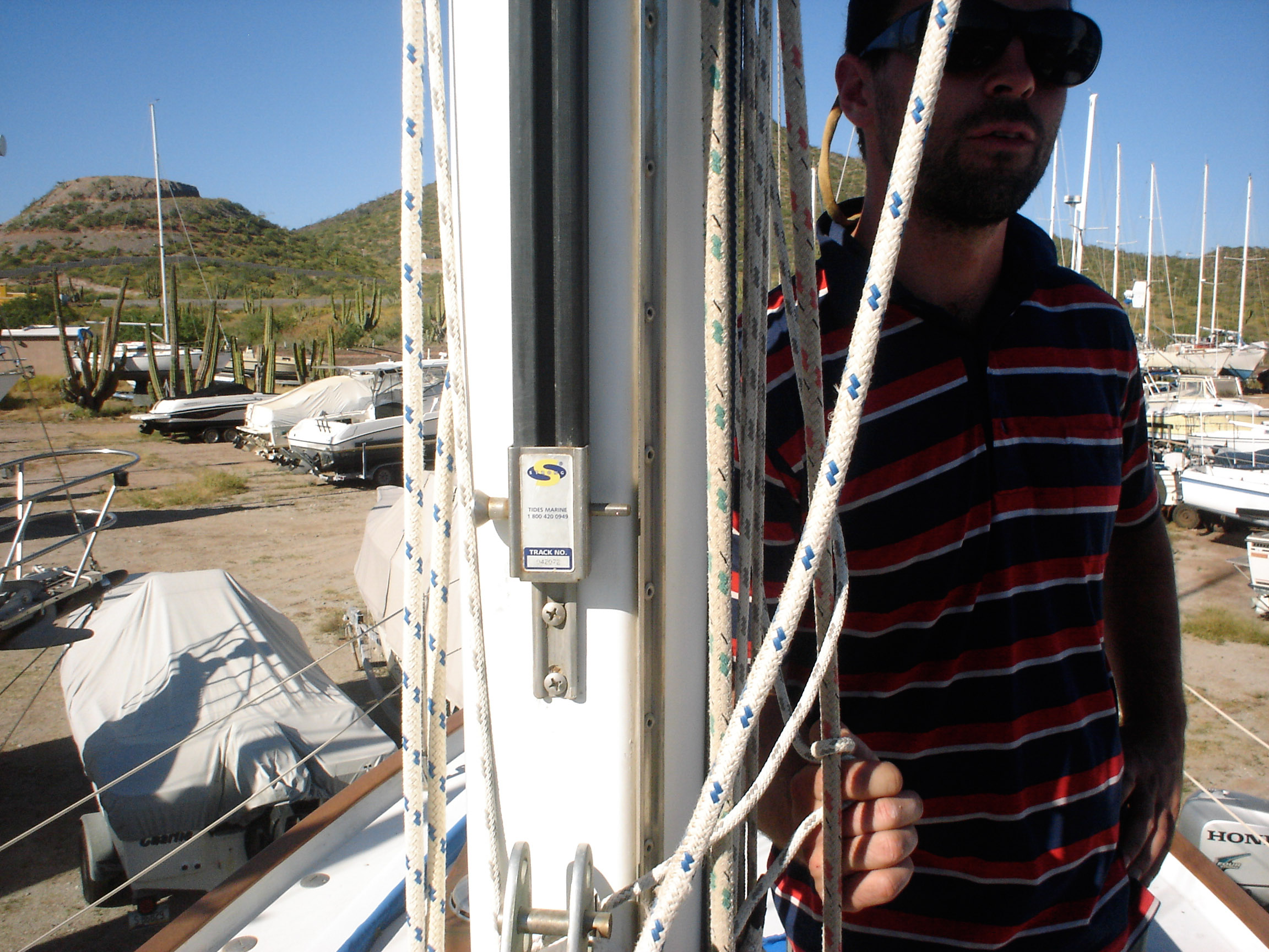
Replaced masthead trilight, LED bulb
We purchased a FirstStar LED trilight bulb, which is conveniently a light-activated anchor light and trilight all in one bulb that fits a standard socket (only two conductors needed; switch the polarity to switch the function). Our old masthead housing wasn’t a standard socket, and was nearly opaque besides. We replaced it with a standard Aqua Signal series 80 fixture. But we weren’t happy with how low the housing sat–the visibility was blocked by other mast hardware. So jonny bought some c-board and we mounted the fixture atop four stacked 1″ pieces of c-board. I even routed the wire through the c-board to come up exactly underneath the fixture, to avoid water intrusion. We’re very proud of the result.
-
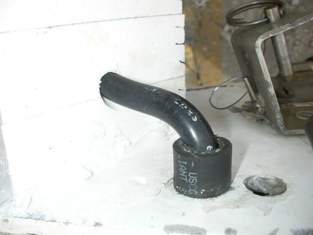
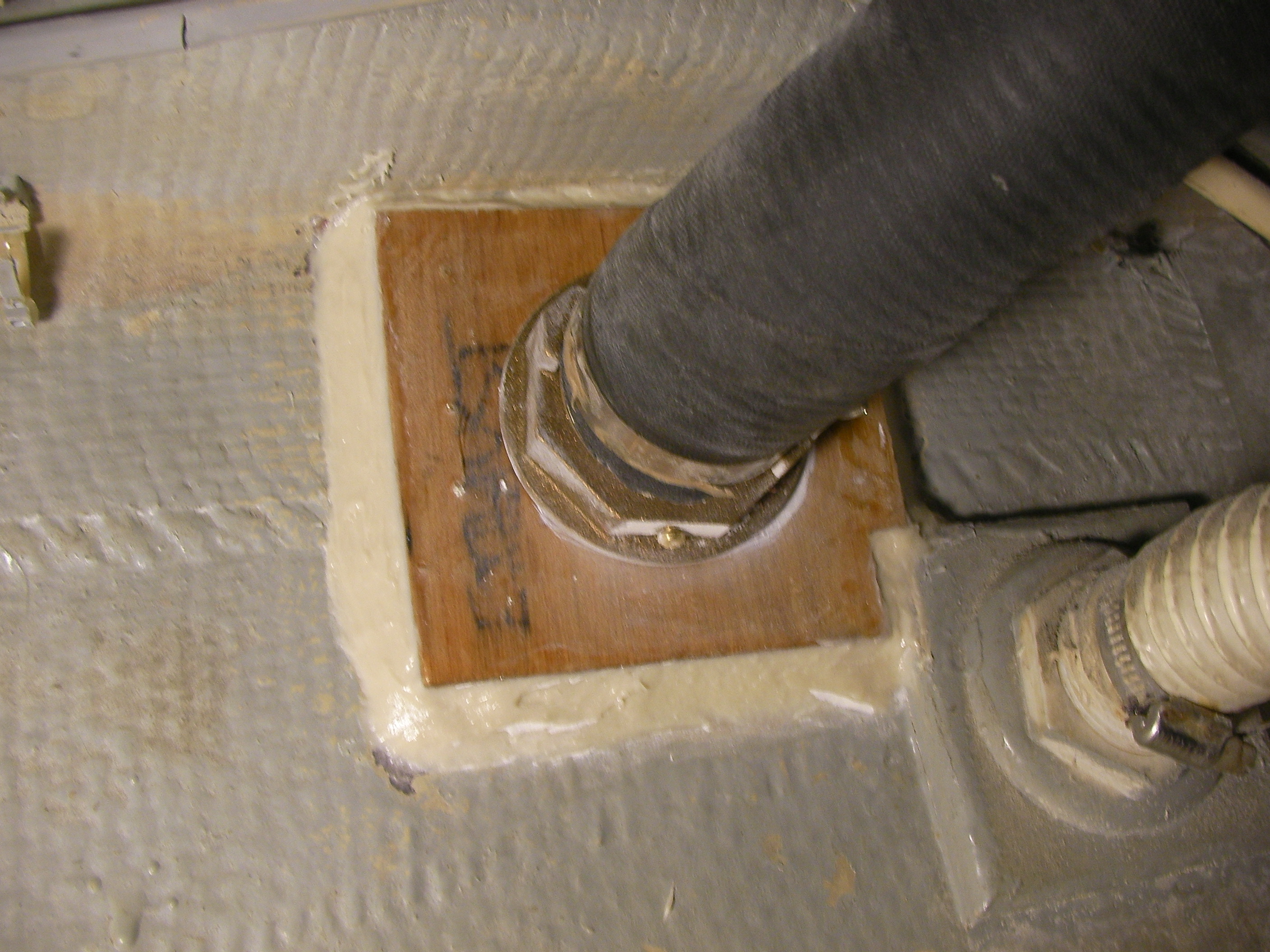
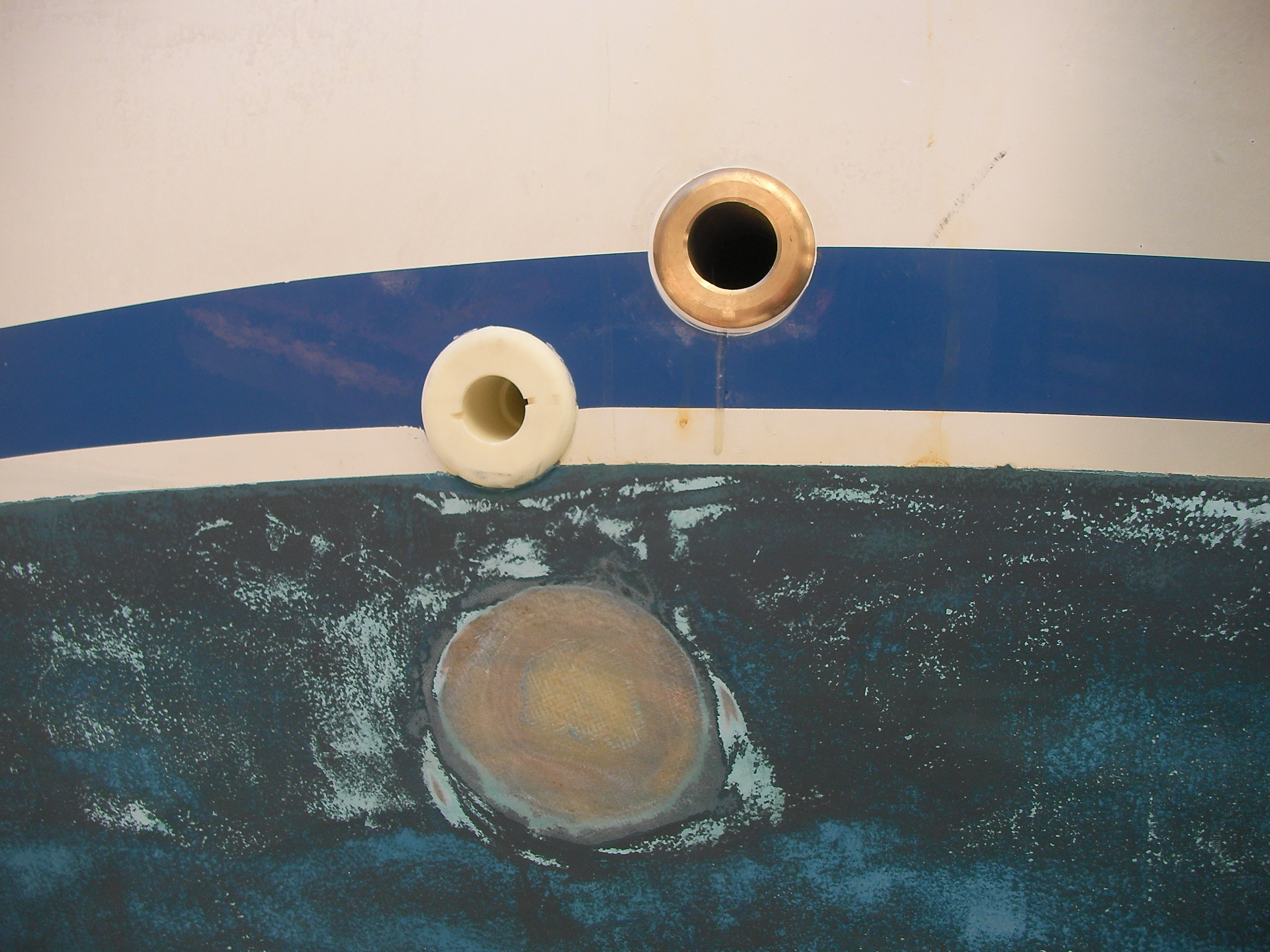
Moved engine exhaust through-hull
The through-hull was a few inches below the waterline. The exhaust through-hull should never be below the waterline, for two reasons: 1) you need to be able to see that water is coming out of the exhaust, to be sure that raw water is cycling through the cooling circuit 2) there is greatly increased possibility of seawater backing up the exhaust and flooding the engine–which is a bad bad thing to do to an engine
We moved the engine exhaust through-hull up above the waterline a few inches, and glassed over the old hole. The old engine through-hull had a janky fitting to connect to the hose, which was prevented from leaking solely from excess 5200. So we found a through-hull threaded on the bottom for the nut, with barbs at the top for the hose. It’s above the waterline now so we elected not to put a seacock on it.
SANYO DIGITAL CAMERA -
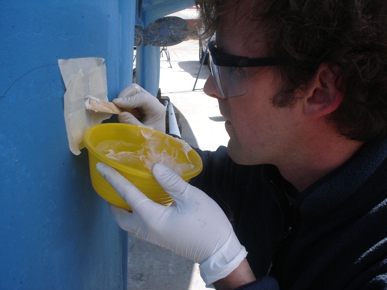
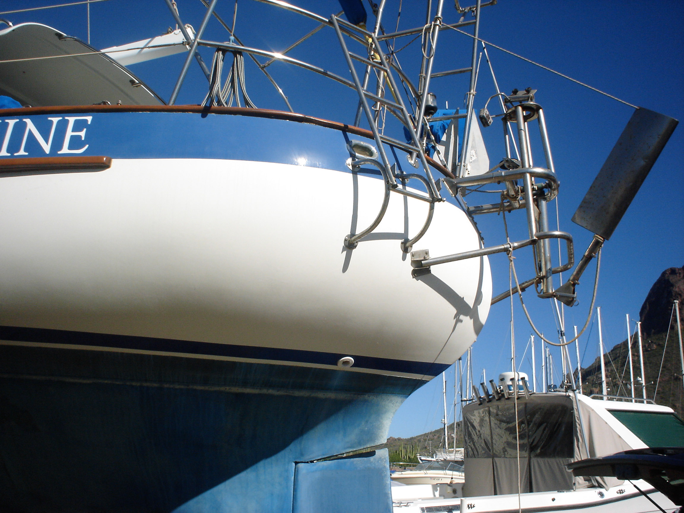
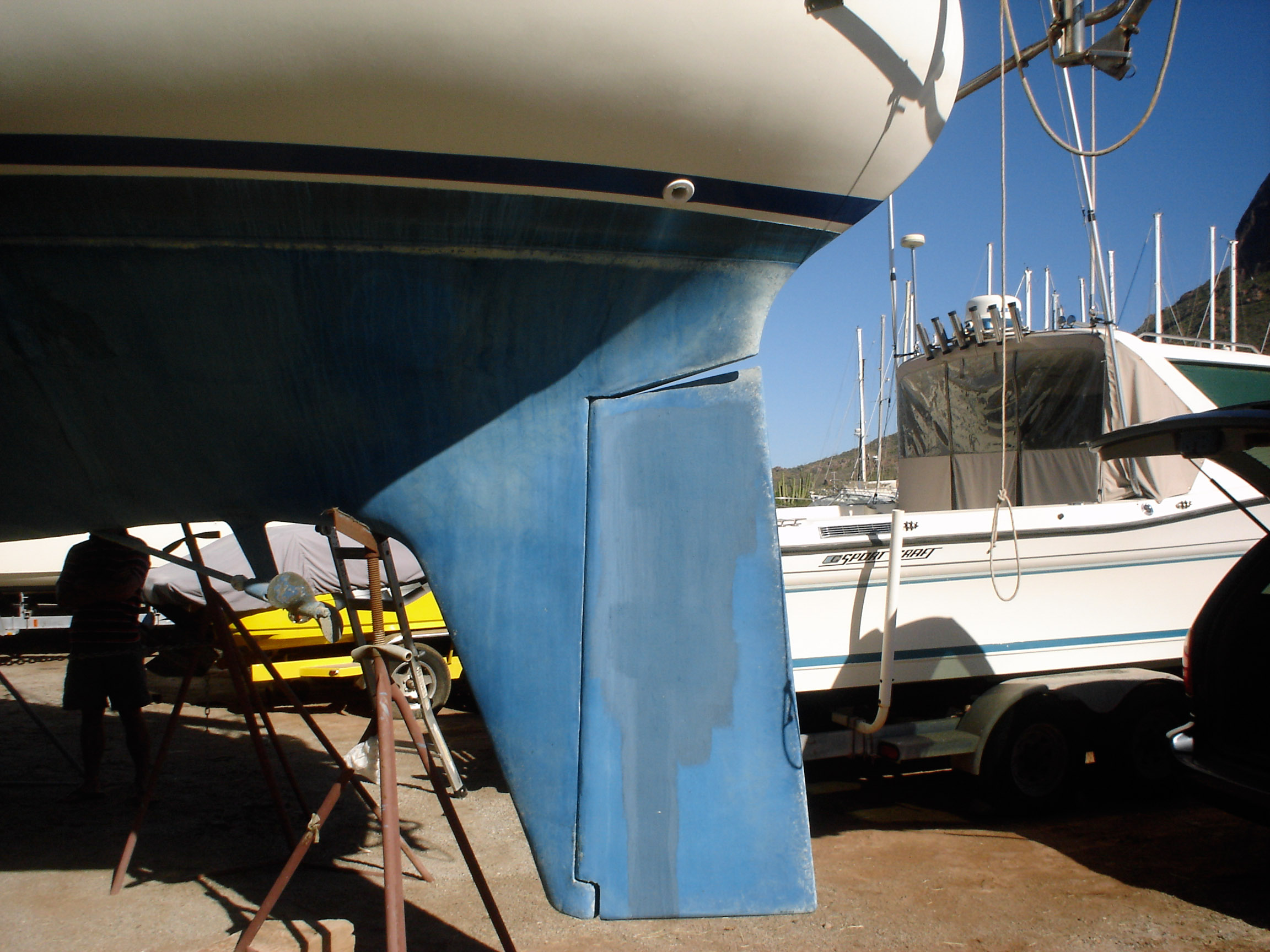
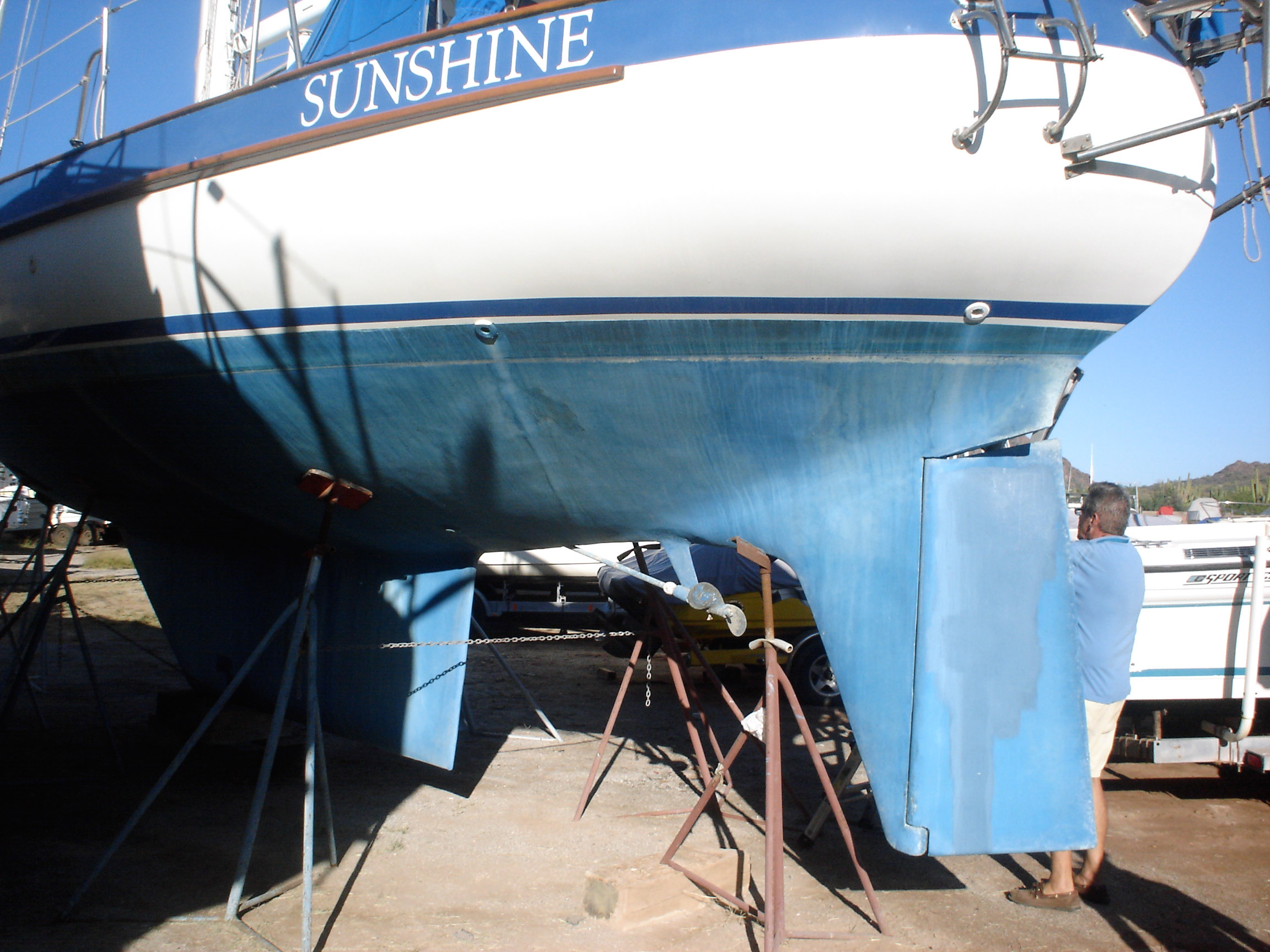
Repaired delaminated rudder
Our rudder delaminated (fiberglass pulled away from the foam) very slightly, no more than 1/8″, from sitting in the mexican desert where the sun would expand and contract it every day. I know that it happened there, because the yard workers repaired it and it sat for awhile without sailing, and it delaminated again while sitting there. The only really important issue is whether there is water in the rudder that is corroding and rotting away the internal metal structure. If that happens, the metal tabs inside can break off and you can lose your steering–which would be very bad indeed. There was no water in our rudder (well okay like two drops) so the delamination that we had wasn’t very alarming. But we repaired it anyway. We drilled holes and injected epoxy using a syringe, then filled the holes with thickened epoxy, and then eventually sanded these fair before priming and bottom painting.
-
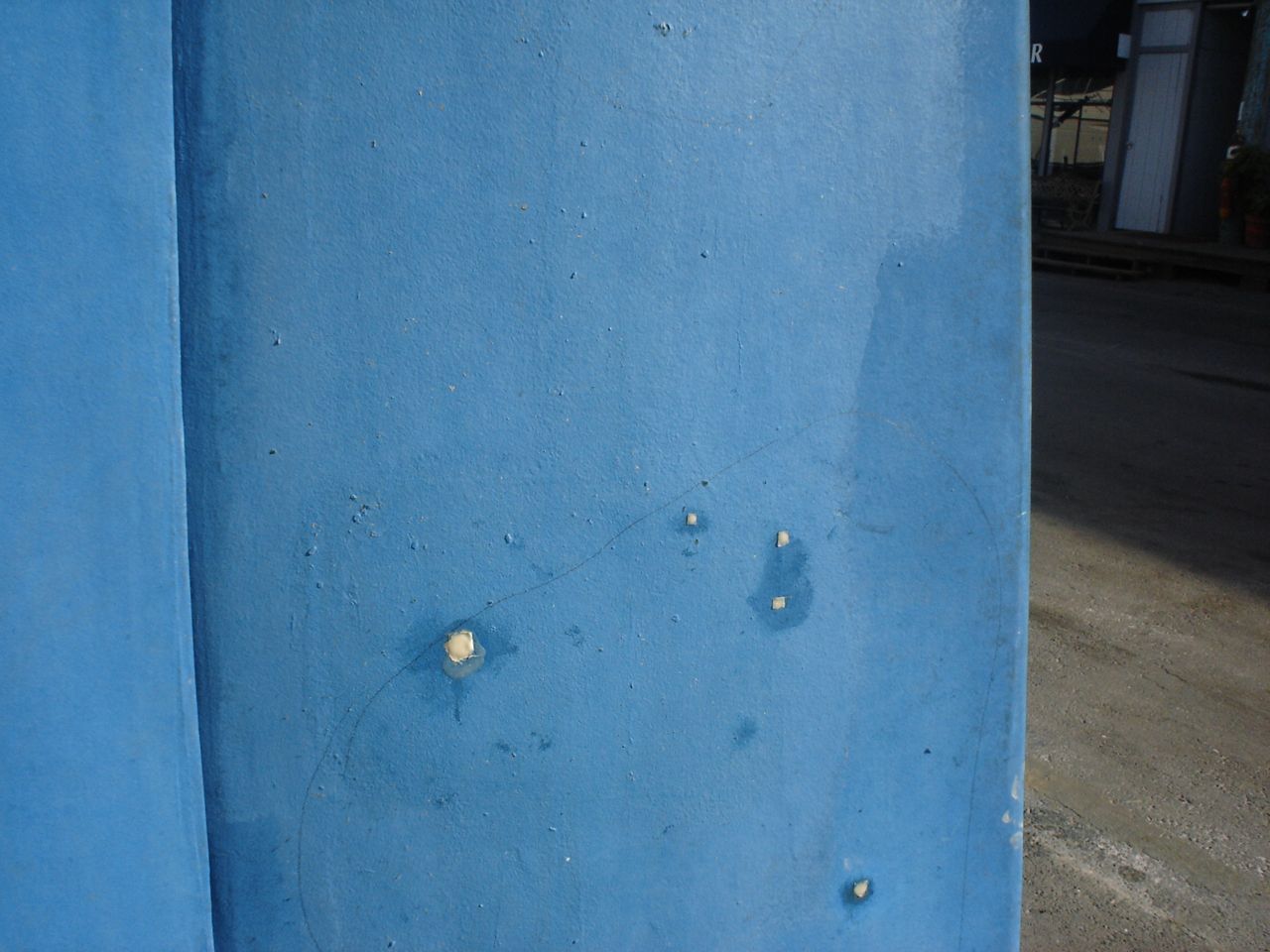
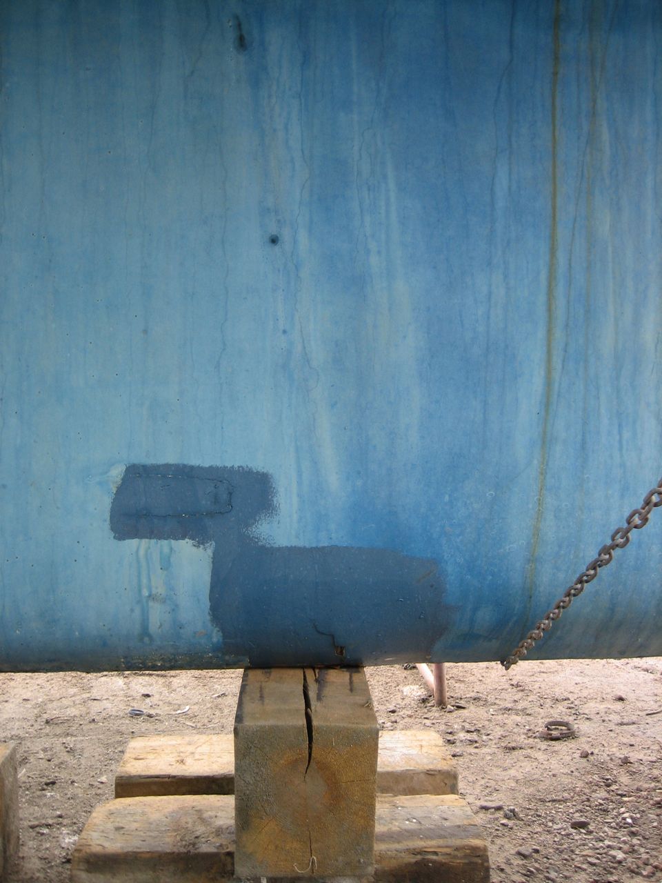
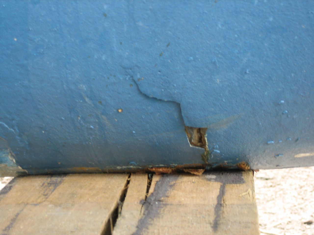
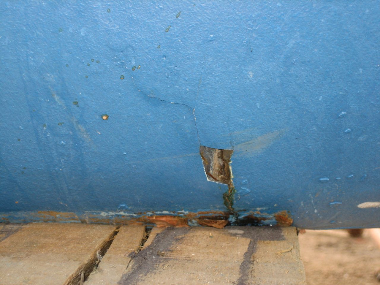
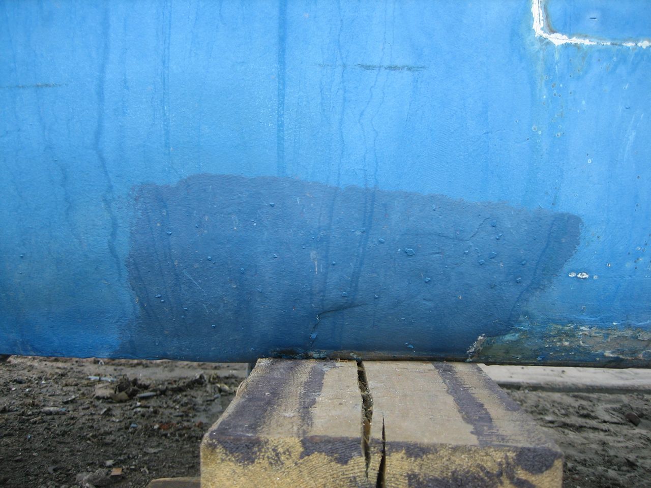
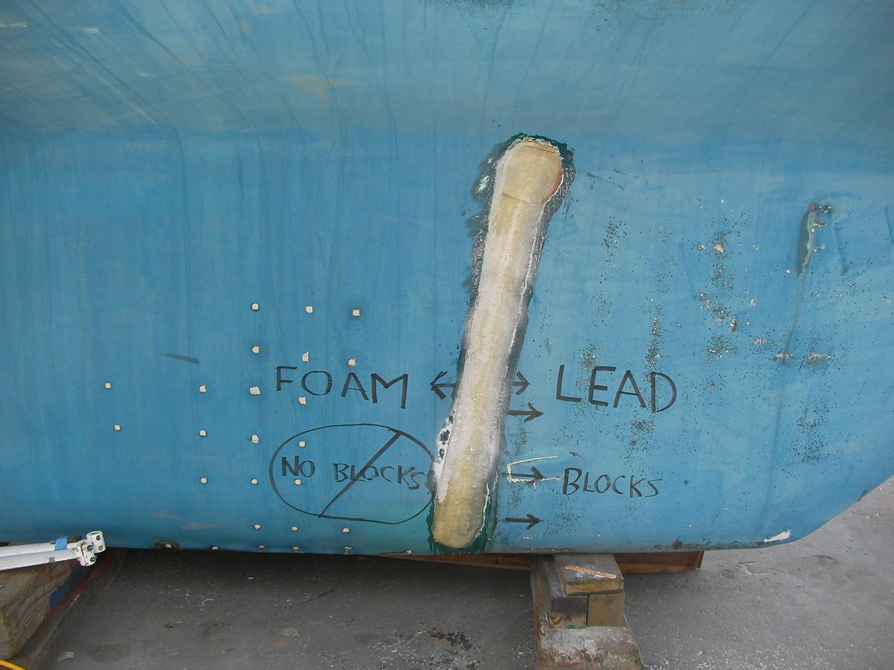
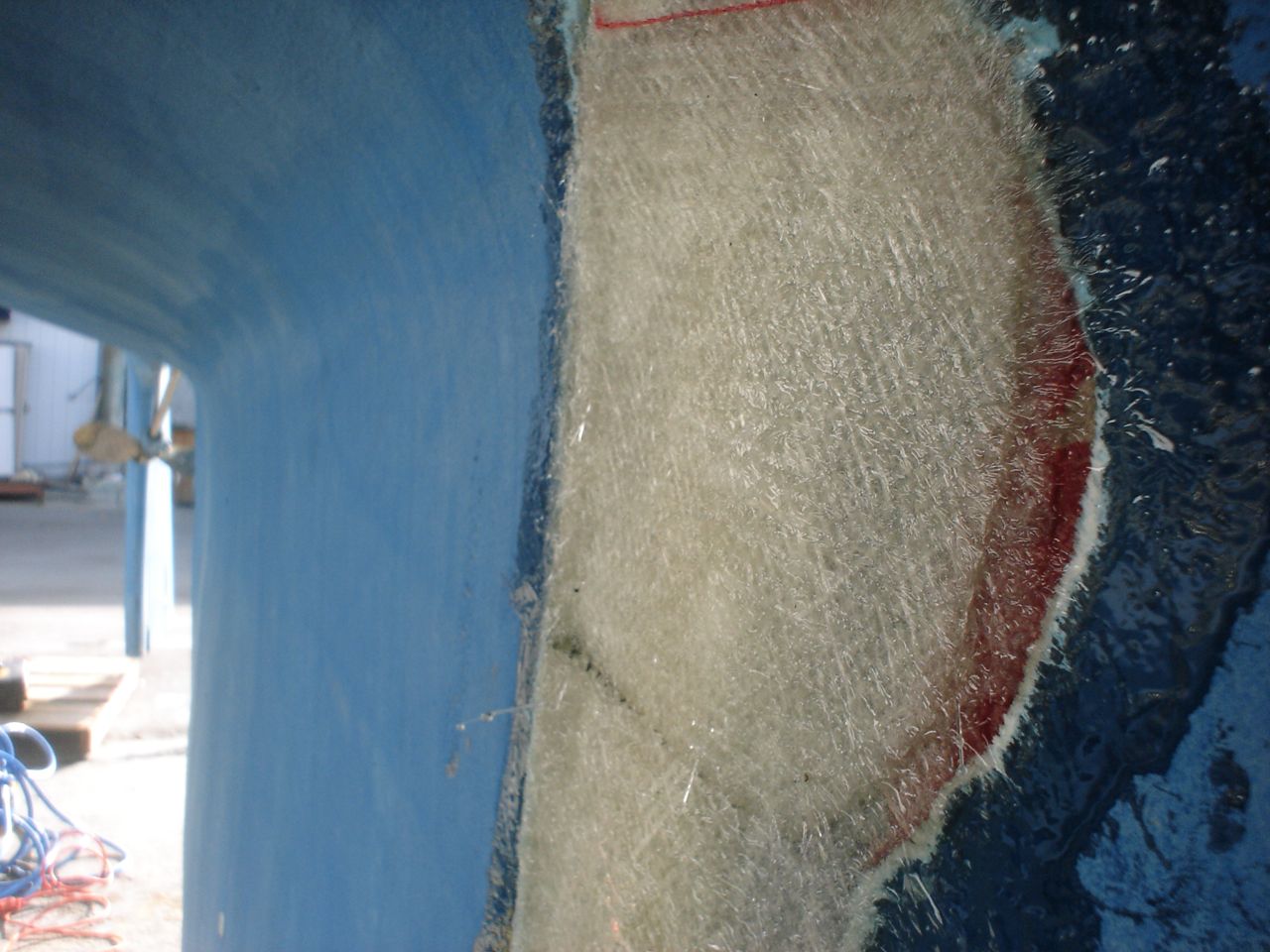
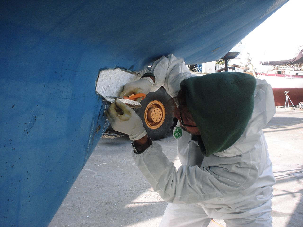
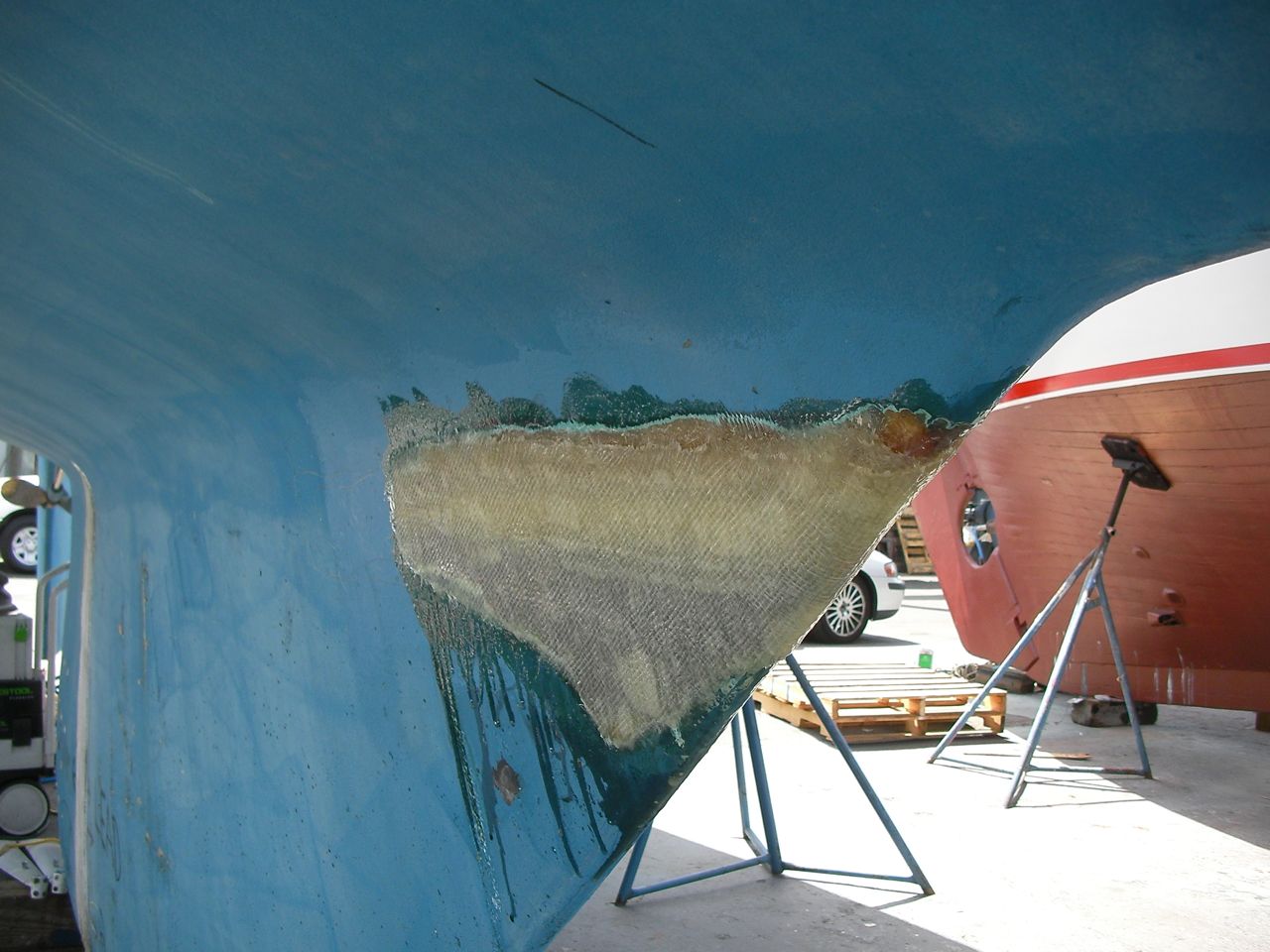
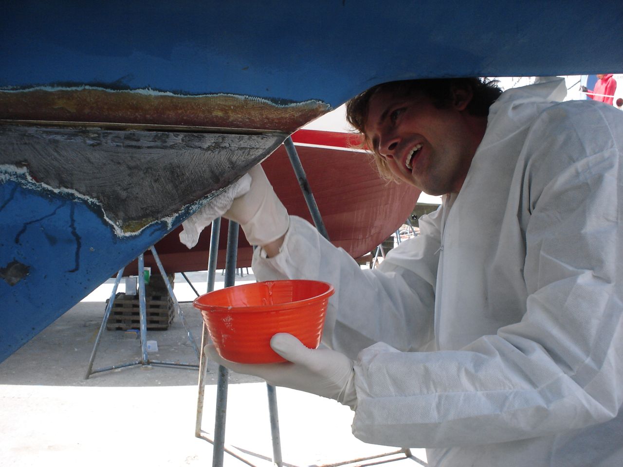
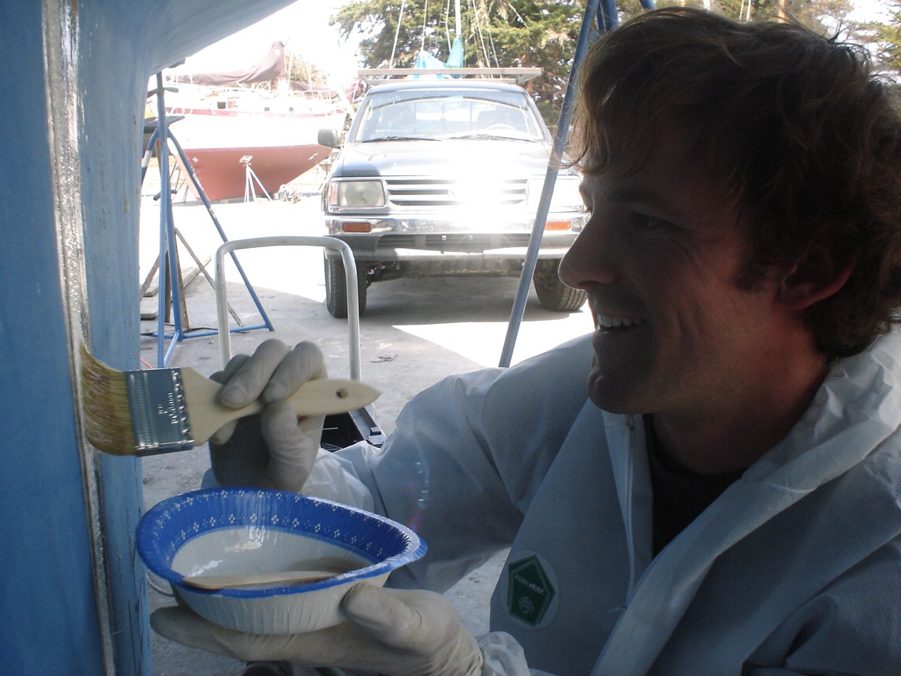
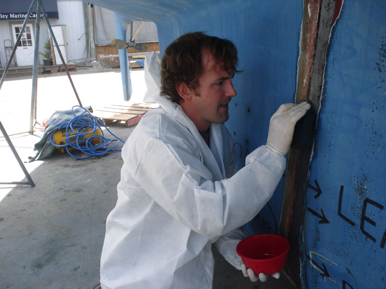
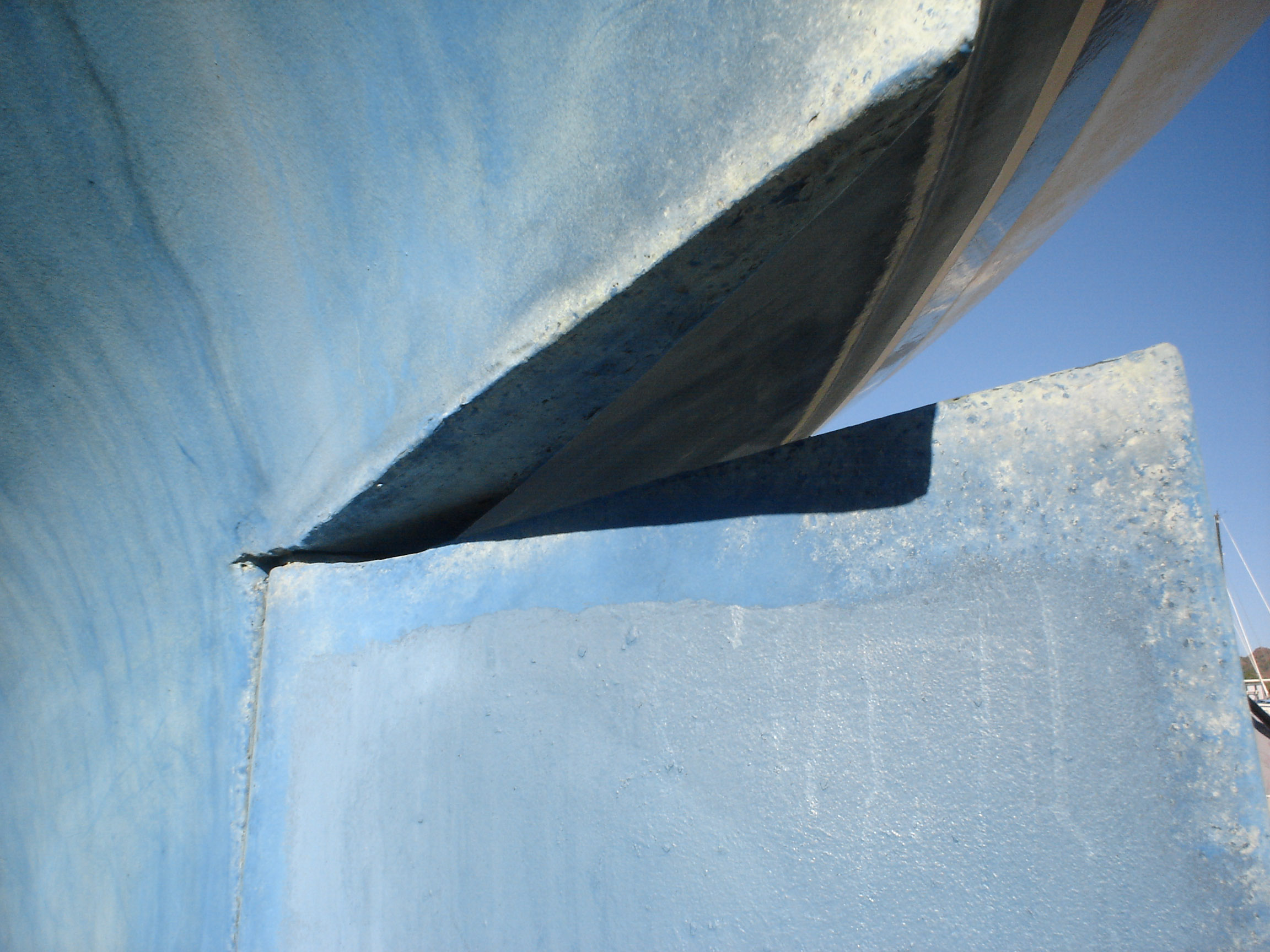
Repaired keel damage
Our keel is half lead, half foam. The front half is lead, the aft half foam. The problem with this is that the join between the two is apt to crack–the keel flexes, the yard sets it down on the foam, maybe even just sailing it, whatever did it, it cracked on us and was admitting/weeping water. (Sometime after our hull number, uniflite wised up and started making the bottom half lead, top half foam.) Down in mexico, I drilled a ton of holes into the foam, bottom and sides, in order to drain the water that was living in there. I also ground down the join so it could dry out. Also, the “smile” at the top front of the keel was weeping slightly from a crack in what I believe was the fairing compound they used. I ground this down in anticipation of drying it out and glassing over it also. In the Berkeley workyard we injected epoxy into the holes I had drilled to repair the mild delamination. Then we used knytex fiberglass fabric to glass over the join (many layers–I had gone a little overboard with the grinding). We glassed over the “smile” the same way. Then we ground down/sanded down the fiberglass fair with the hull. Then we used Quikfair (two-part epoxy fairing compound) to fair the areas smooth. Then we sanded these down fair. Then it was ready for priming before bottom painting.
SANYO DIGITAL CAMERASANYO DIGITAL CAMERA -
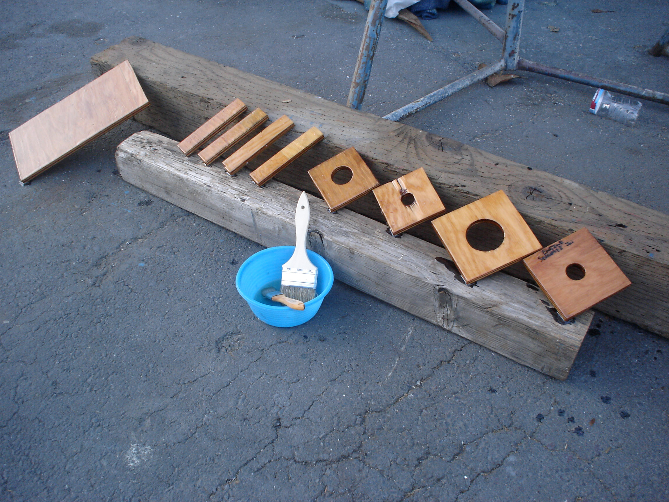
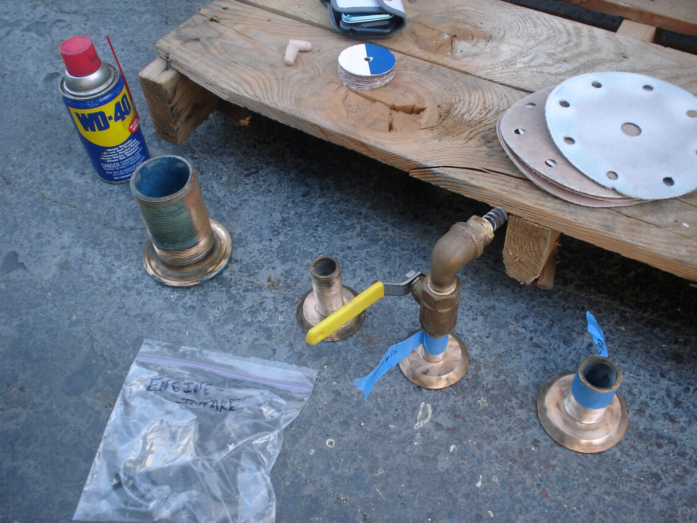
Through-hulls, Seacocks, Backing plates
There were 8 below the waterline through hulls when we bought the boat: one for the depth transducer, one for the impeller transducer, two for the head, two for the galley, an engine intake, and the engine exhaust. Some of the through-hulls had seacocks, others had inline ball valves screwed onto the through-hulls. The engine exhaust had no seacock or valve. Only two (the head in and out) has sufficient backing plates. In all cases, the seacocks were not screwed down all the way to the hull; the through-hull nuts were screwed down to the hull and the seacocks were screwed on top of them.
We added proper backing plates to every below waterline through-hull. The backing plates are 3/8″ marine grade plywood, saturated with penetrating epoxy to waterproof them.
We installed flanged, ball-valve seacocks on each through-hull. The seacocks are lag screwed into the backing plates (not all the way through the hull). The seat for the lag screw was drilled out and injected with thickened epoxy, so that the lag screws are not penetrating into the wood in any spots.
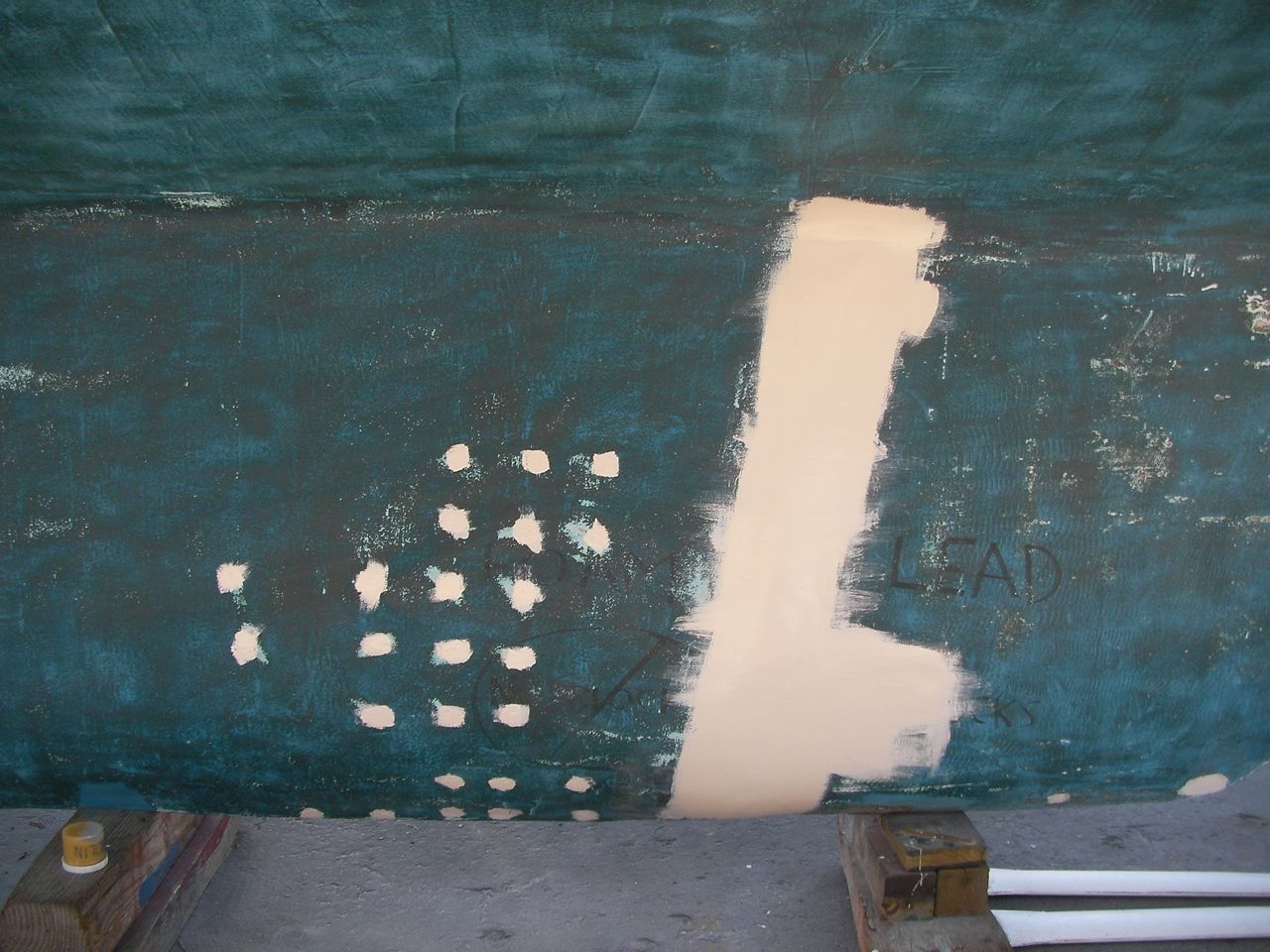
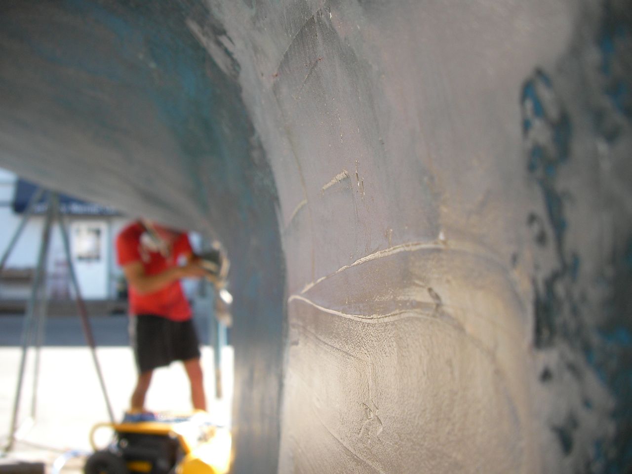
We ran into numerous roadblocks during these jobs. 1) A few of the old through-hulls were not long enough after adding the backing plate, so we had to purchase new ones, measure the amount of thread needed inside the boat, then cut off the excess (so the seacock will fully screw down to the backing plate). 2) After installing the backing plates in the galley, we discovered that they weren’t close to parallel to the hull, so jonny spent hours grinding them down to an angle so the seacocks would sit flat (see the video below). 3) All the old through-hulls on the boat were insets, with a countersunk flange. Unfortunately, the through-hulls at Svendsens has differently shaped flanges. So we glassed over the two head through-hulls (you can see this in the third picture below), drilled out new holes, and then used standard mushroom through hulls. This ended up taking far longer (the glassing part) than I thought it would. In retrospect, we should have shaped the old insets to accomodate the flanged through-hulls that we could buy at Svendsens, using the dremel and/or thickened epoxy to make a new seat. 3) It took some time to mark where the lag screws would go, drill out oversized holes, fill them with thickened epoxy, remark where the lag screws were to go, then drill pilot holes for the lag screws.
SANYO DIGITAL CAMERASANYO DIGITAL CAMERASANYO DIGITAL CAMERASANYO DIGITAL CAMERASANYO DIGITAL CAMERASANYO DIGITAL CAMERASANYO DIGITAL CAMERASANYO DIGITAL CAMERASANYO DIGITAL CAMERASANYO DIGITAL CAMERASANYO DIGITAL CAMERASANYO DIGITAL CAMERASANYO DIGITAL CAMERASANYO DIGITAL CAMERASANYO DIGITAL CAMERASANYO DIGITAL CAMERASANYO DIGITAL CAMERA -
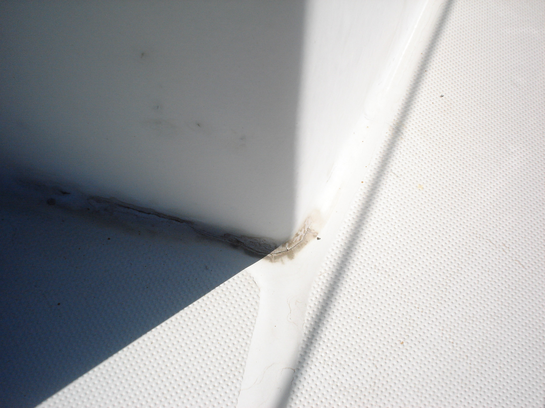
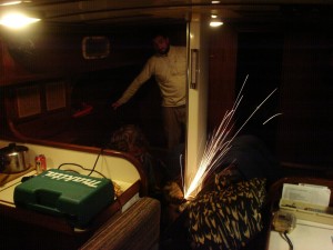
Replaced Propane Locker Drain
The drain for the propane locker was completely clogged, and the locker itself was full of rust colored junk (clearly the hatch gasket is not working and will need to be replaced). Jonny and I cleaned the locker and replaced the drain one dark night in mexico.
-
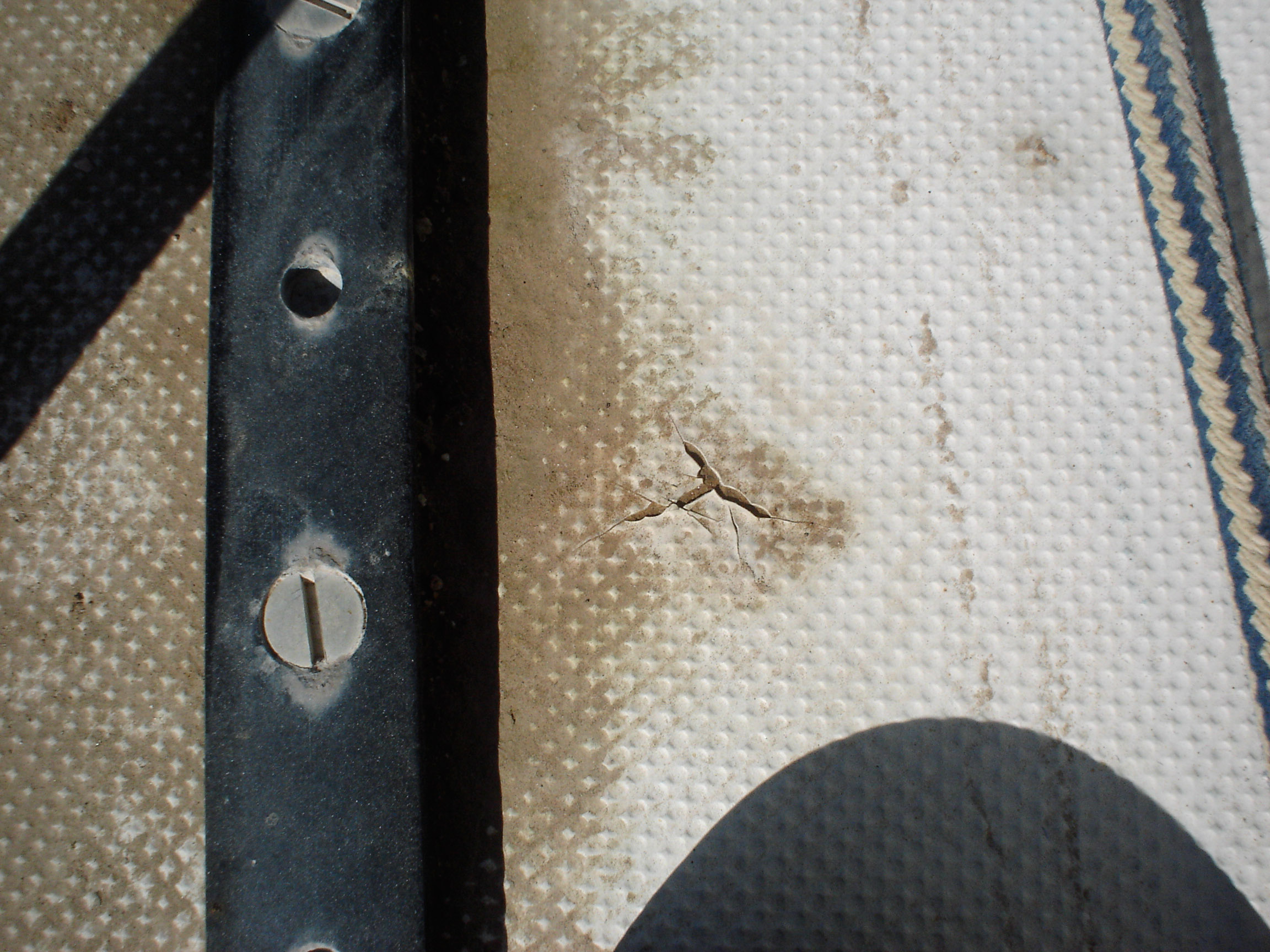
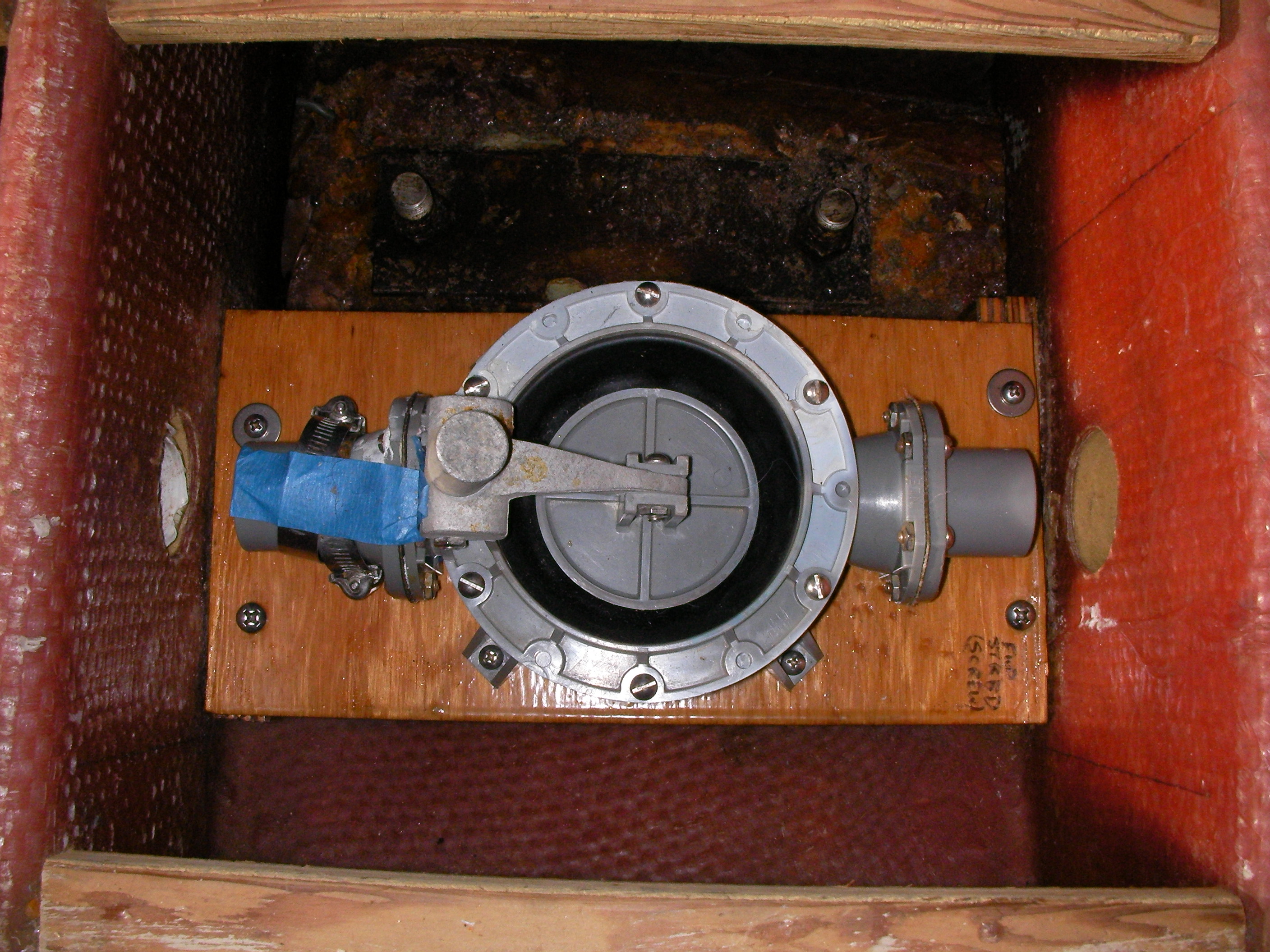
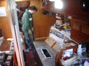
Serviced manual bilge pumps
Jonny and I completely dismantled the two manual bilge pumps, cleaned and inspected every part, and put them back together. They were in pretty good shape and probably didn’t need to be given the full treatment, but now we have more confidence in them.
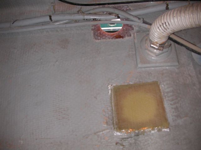
Upon removing the pump that was in the bilge, I discovered that it had been mounted to an untreated piece of lumber, and that the board had been screwed into the fiberglass with low-grade steel, which at some point just rusted in half, so when I grabbed the pump the whole board came right up with it.
So I remounted it on a piece of marine grade plywood, painted with a few coats of penetrating epoxy, mounted mounting strips in the bilge, and put it back down there with through-bolts on everything.

SANYO DIGITAL CAMERA -
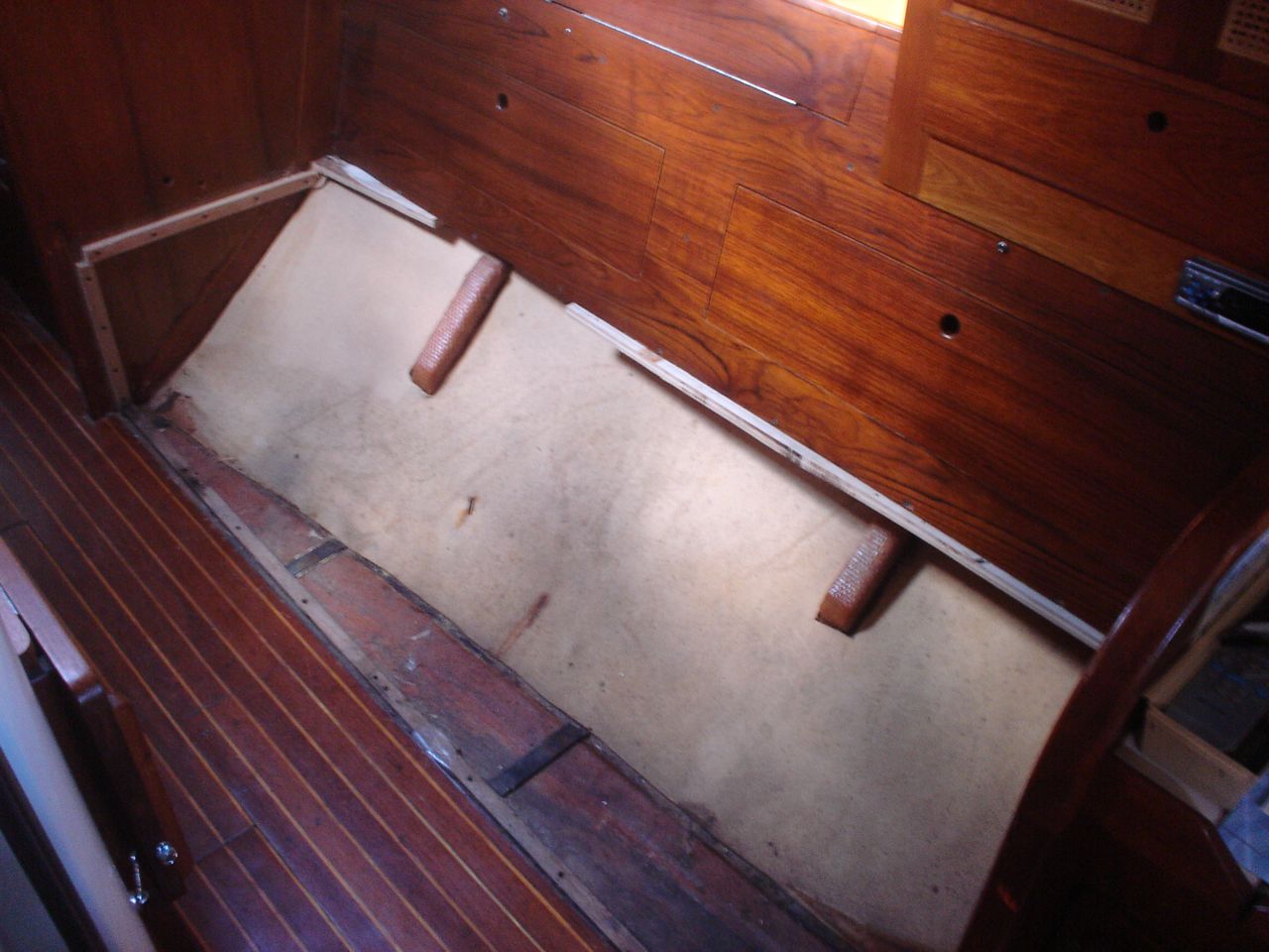
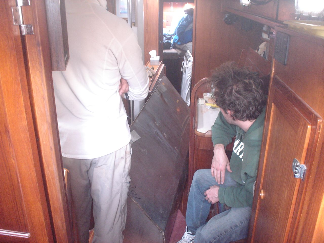
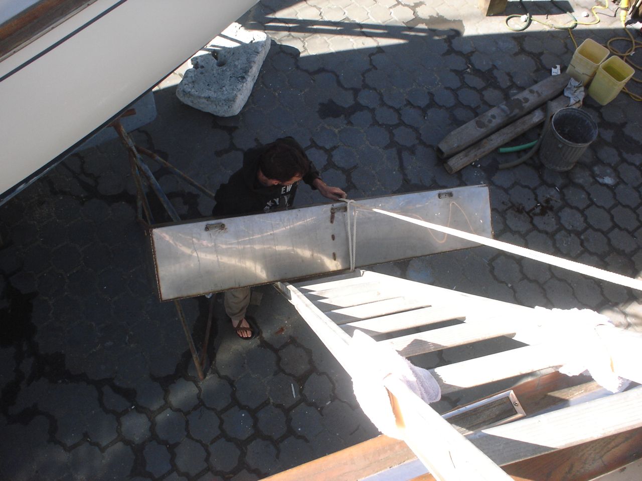
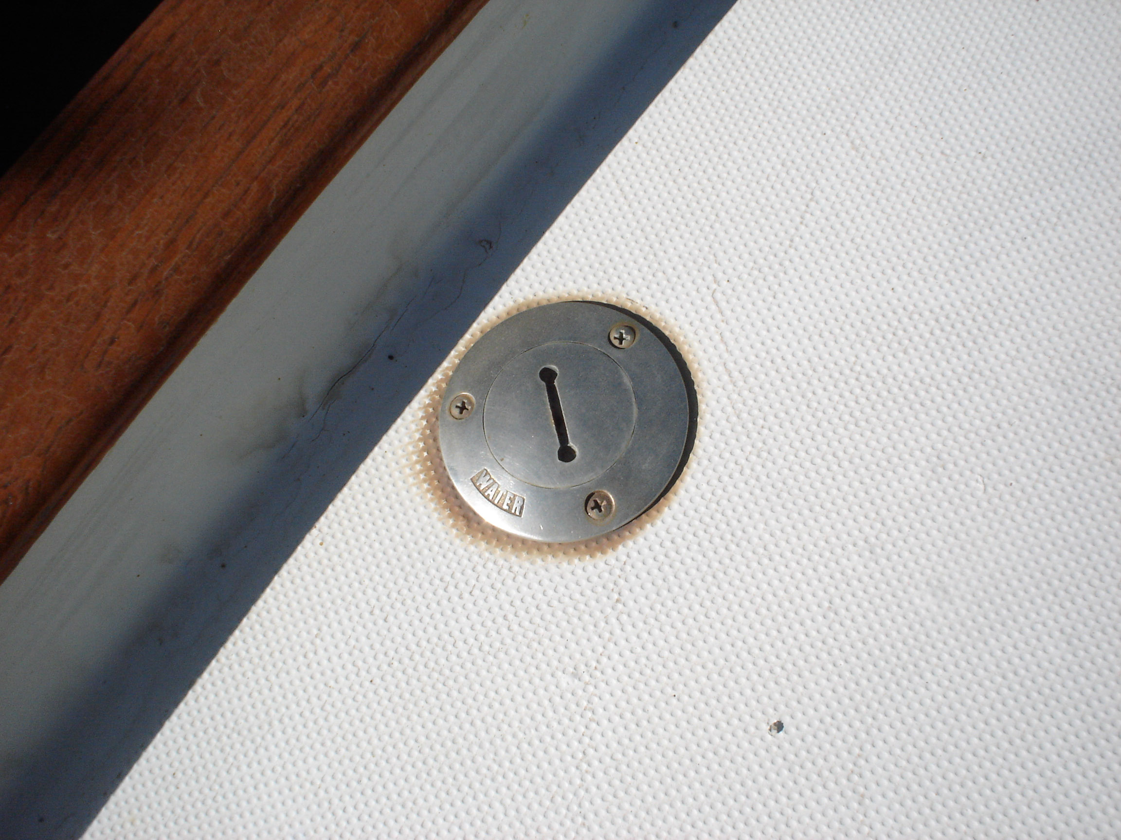
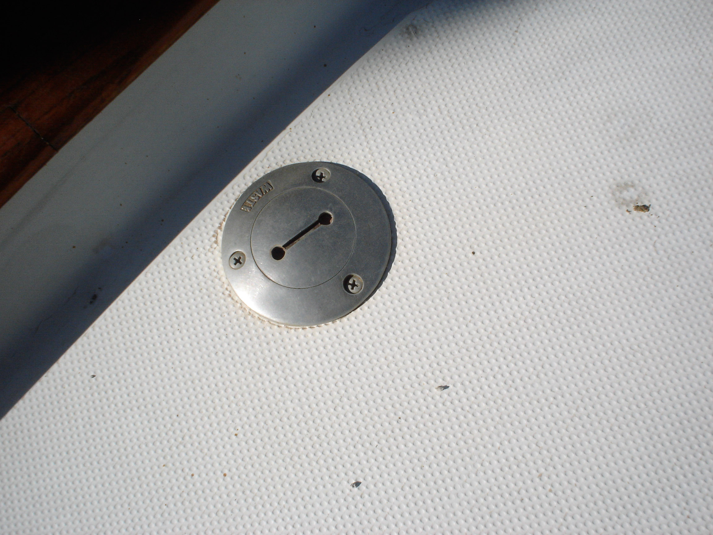
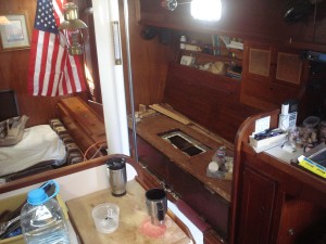
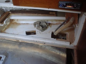
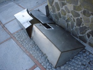
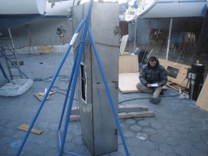
Replacing Watertanks, Pt I (removal)
Over the christmas work trip to mexico we removed the existing, leaking, stainless steel watertanks from the boat. It was an extraordinarily tedious job.
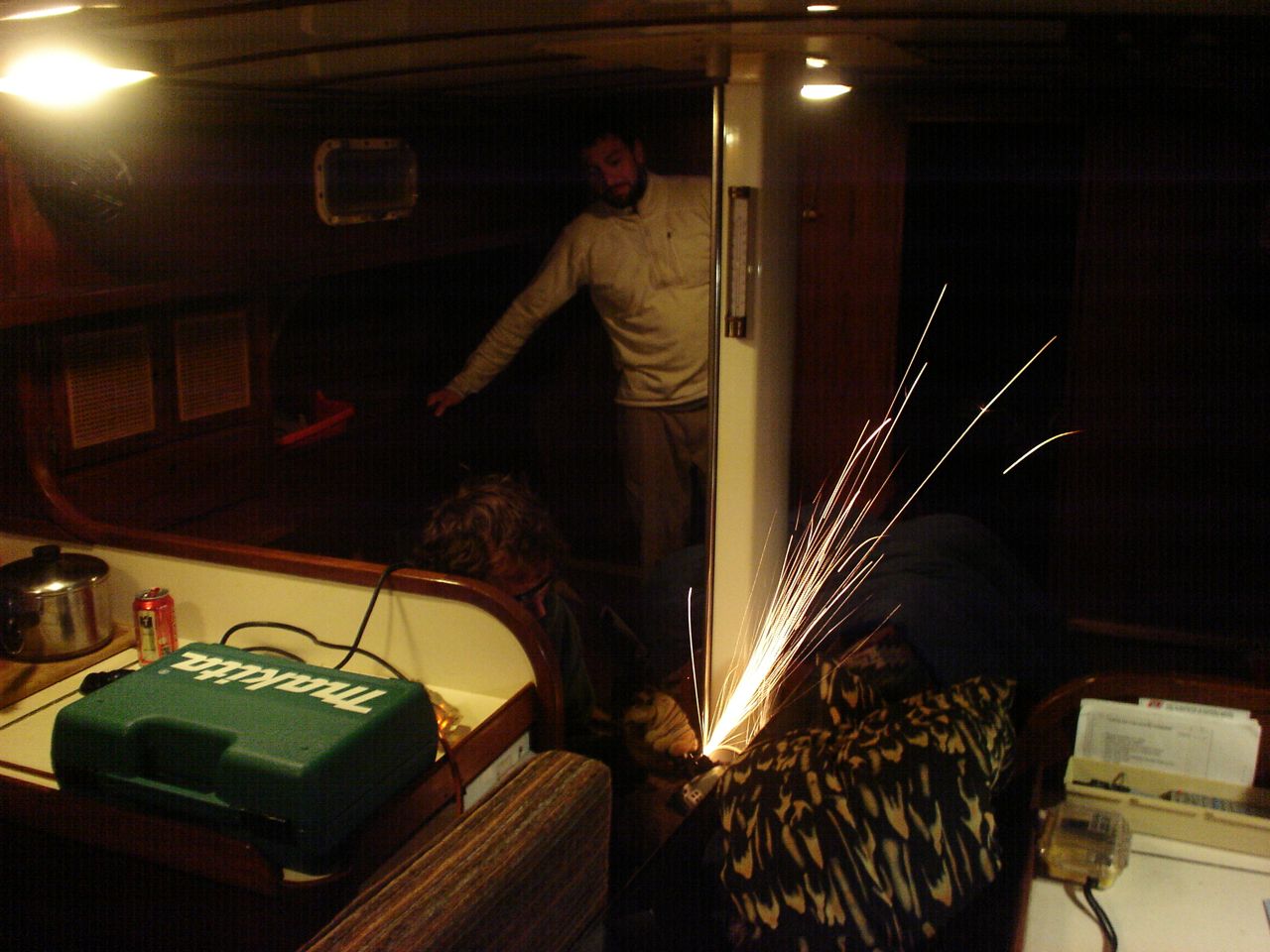
Our idea is to replace the stainless tanks with our own home-built West System plywood/epoxy tanks. We have 150gallons of tankage; if we had less I would have elected to use Ronco plastic tanks, but they don’t make ones near big enough and I didn’t want complicated plumbing stringing multiple tanks together. The watertanks are bolted to the hull in two places on the backside of the tank (each one), via a machine screw to fiberglass stringers. The tanks were installed in the boat and the settees and storage were built around them, so it is necessary to cut out access hatches through the bottom of the storage compartments behind the settee. We determined where to cut these access hatches by using a mirror and a yardstick to estimate the location of each stringer. I really really hate having to cut new holes in the boat, but in this case it truly was unavoidable. The tanks are not identically sized; the starboard tank is slightly smaller. We were able to take the starboard tank out the companionway–it was a very tight fit. After that sigh of relief, we were extremely dismayed to discover that the port tank is larger and definitely doesn’t fit. We went back and forth trying to decide whether we should tear about the companionway trim or cut up the tank. We weren’t sure we’d be able to get the tank out even if we ripped out all the trim, so we elected to cut the tank up down below. This proved to be an epic task, and that’s an understatement.

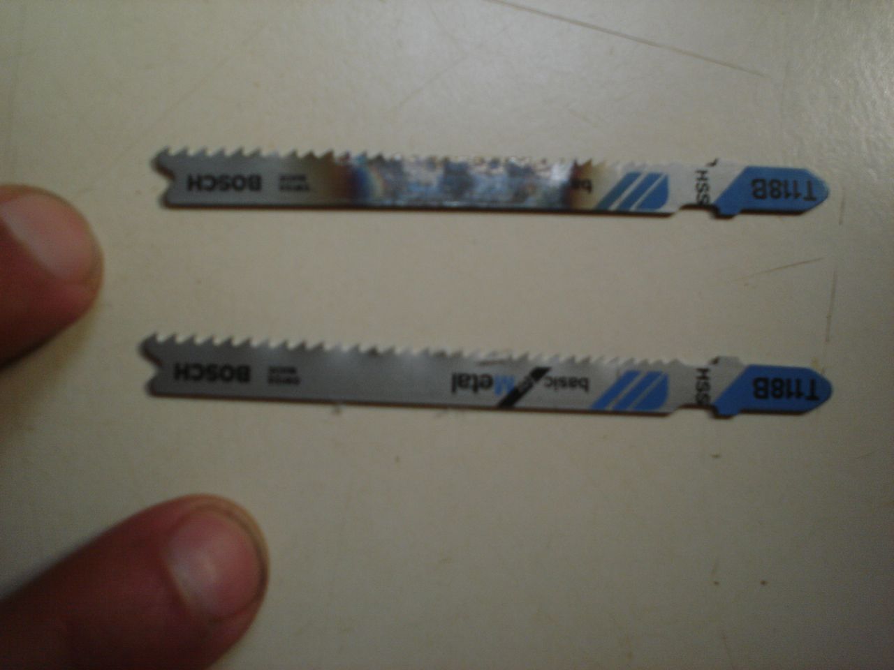
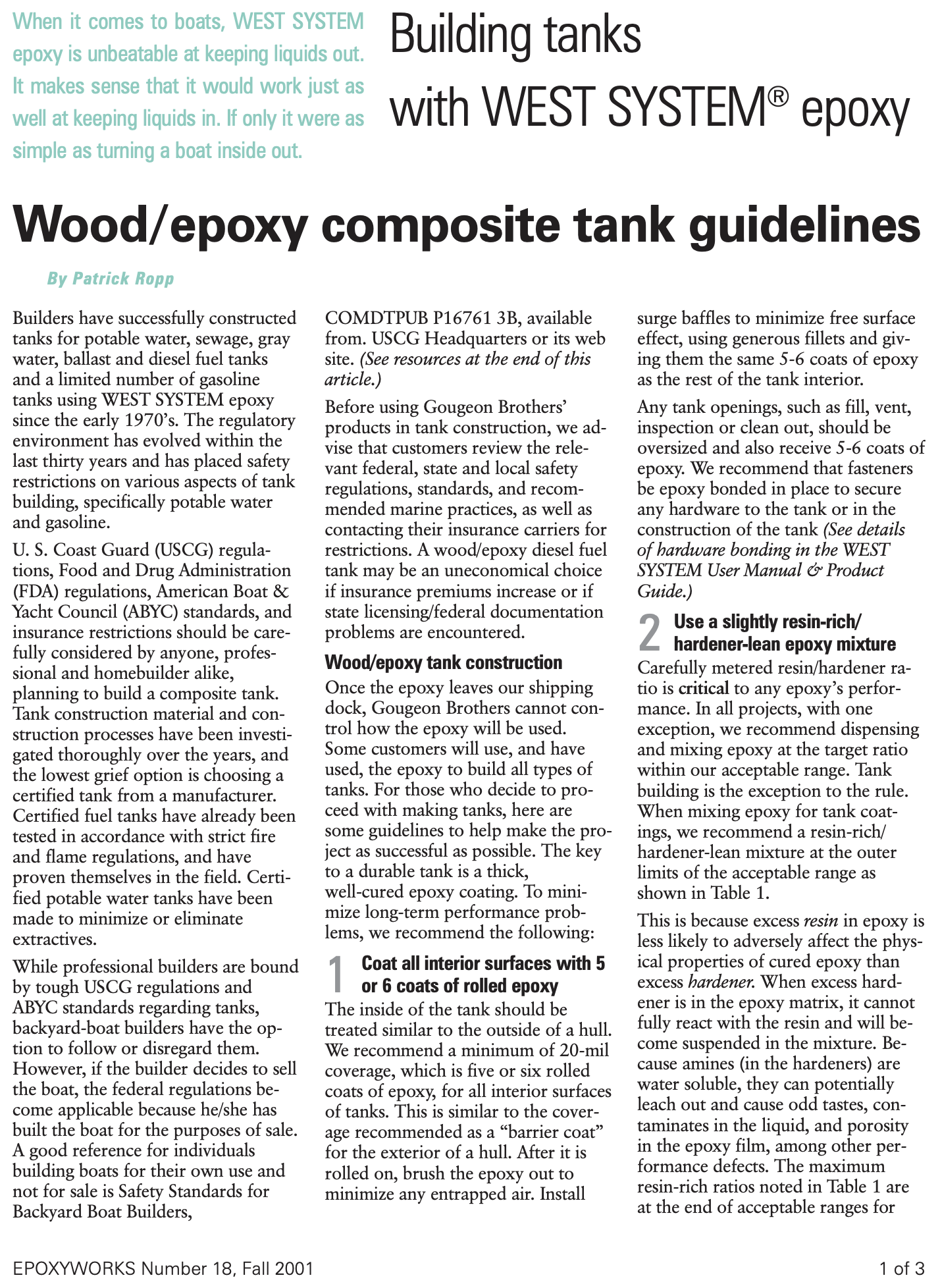
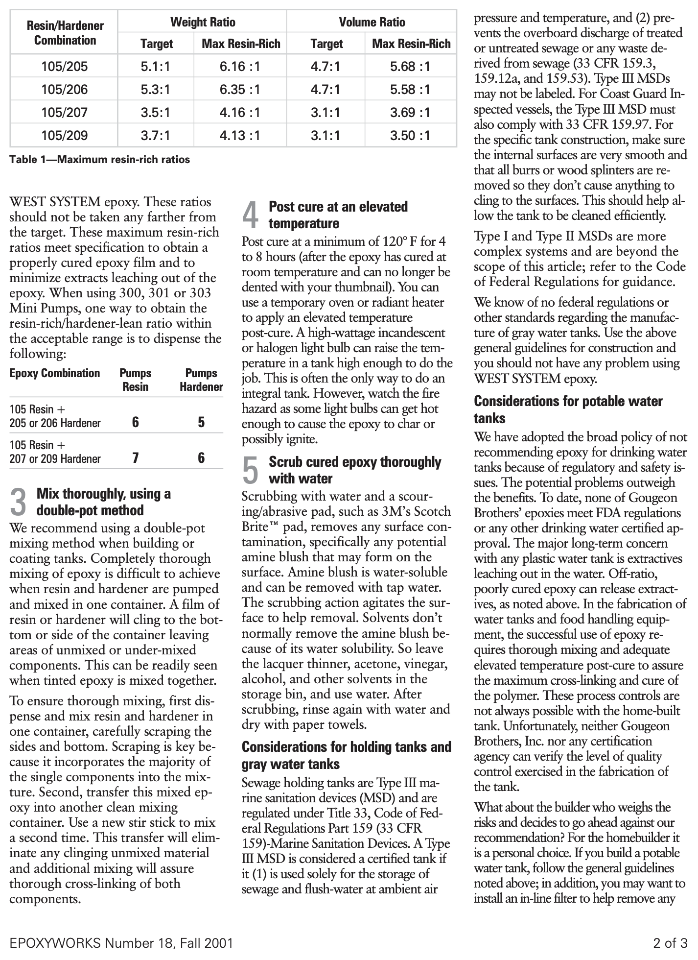
 The tanks are out of the boat. We gave one away to one of the guys that works in the marina workyard, the other was destroyed when we cut it in three pieces. We chose to build our own replacement tanks out of fiberglass, epoxy, and plywood. This may have been a poor decision, but there are no take-backs at this point. We bought wood and epoxy and fiberglass and drove it to mexico, where we spent more money on fiberglass and epoxy (way overpriced). Then we didn’t finish the job and decided to truck the boat up to SF, so it was all a waste of time and money. We’ll be building the tanks up here in SF, as we should have from the beginning. Hindsight is 20-20. I am using the West System epoxy method, and I’m going to follow their special additional instructions (images below) regarding potable water tanks. These special instructions consist of a slight lack of hardener, thorough mixing habits, and a period of elevated temperature for post-curing. I anticipate stage II to take place in May.
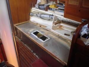


-
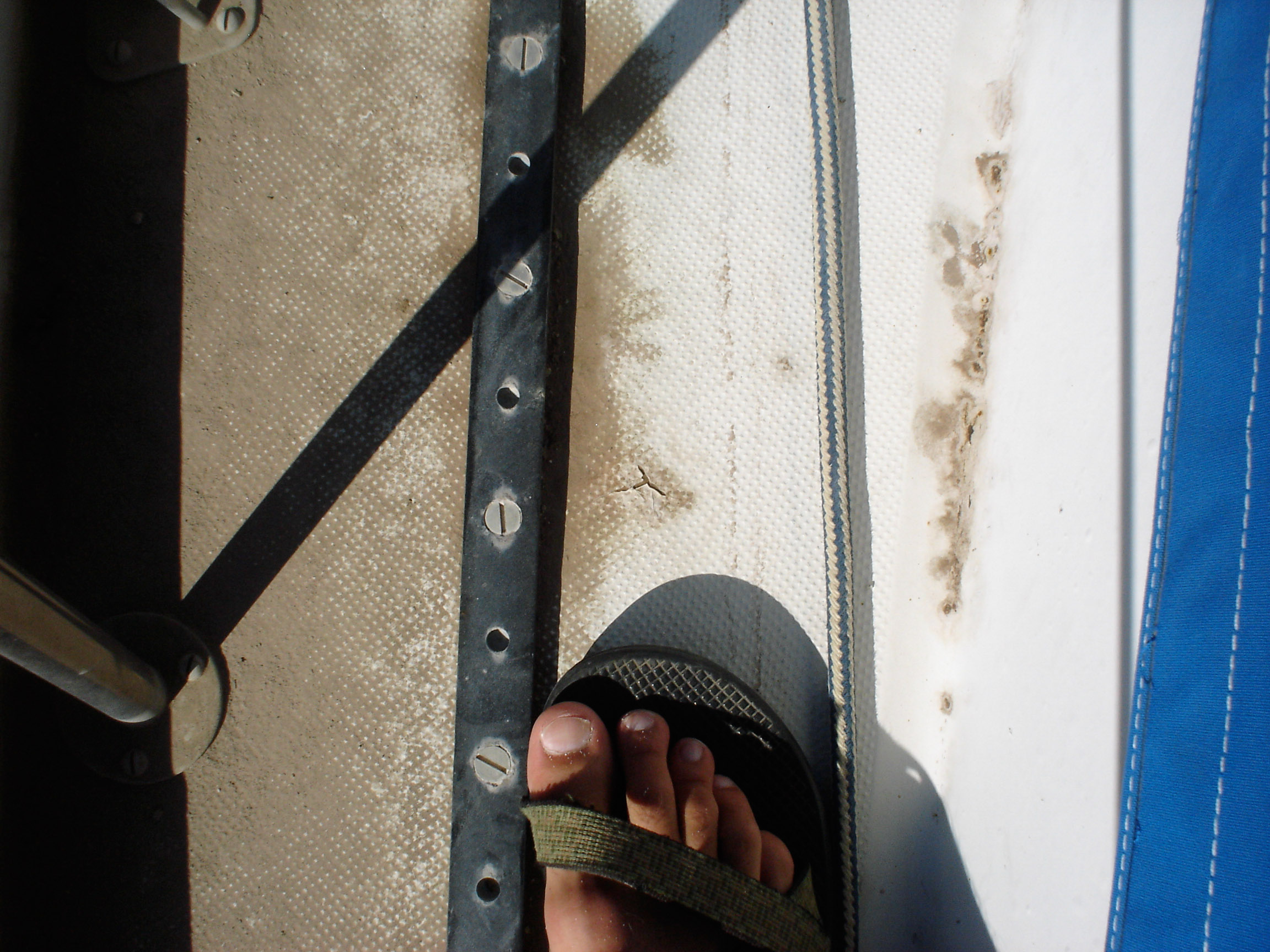
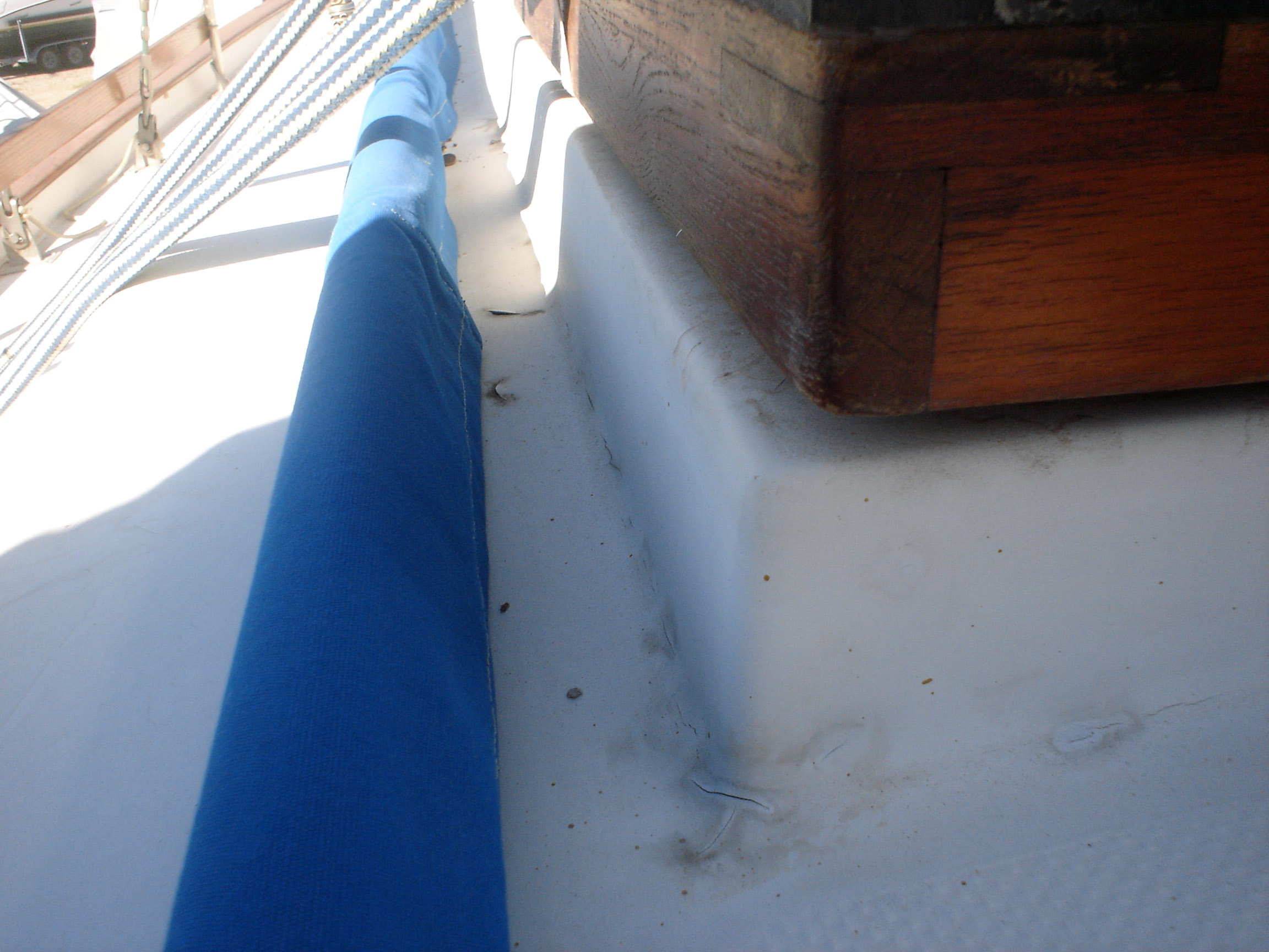
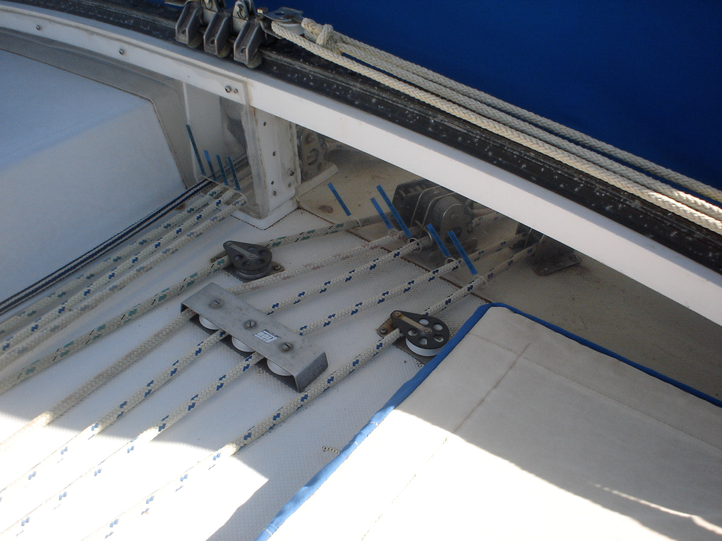
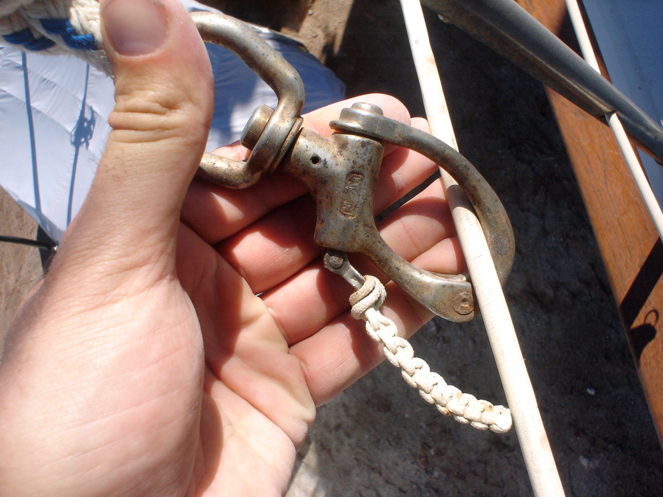
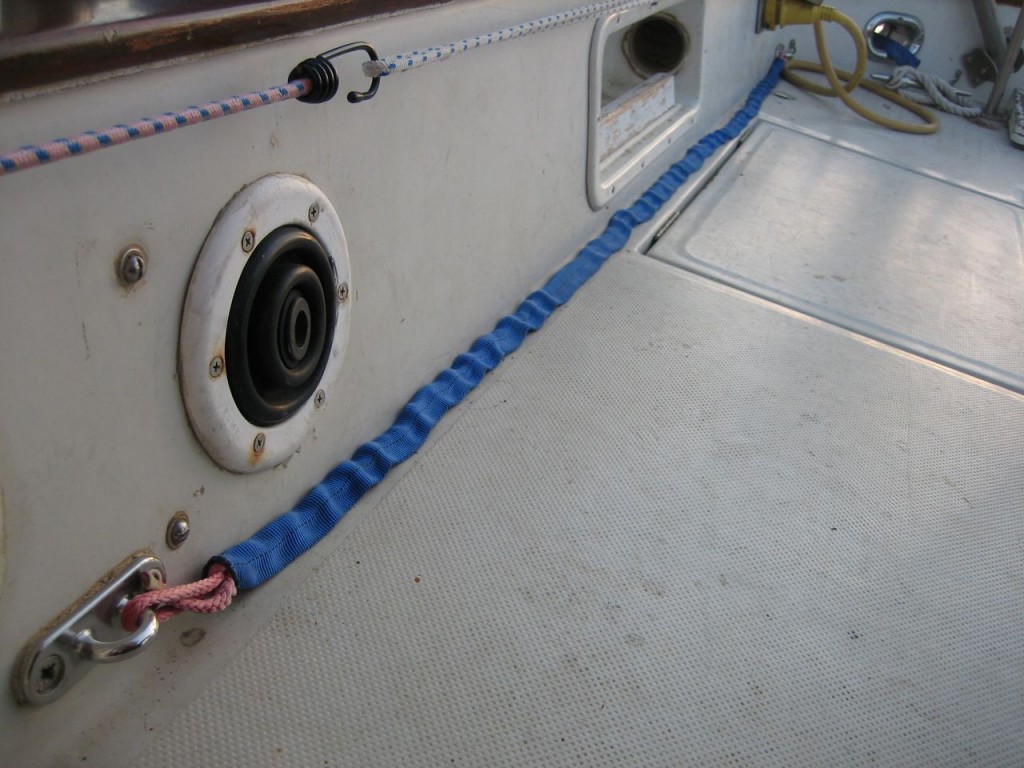
Assembled new jacklines & tethers
Webbing is nice for jacklines because it doesn’t roll under the feet. But it degrades in the sun and the strength goes to shit. Somewhere I read a good idea–thread line down through the center of the tubular webbing and have the advantages of both. So that’s what we did. I bought blue 1″ tubular webbing and 1/4″ amsteel, and jonny did the deed of threading the amsteel through the 40ft lengths of webbing. We made our own tethers by threading shockcord through tubular webbing; one end gets a trigger release snap-shackle (that will be the pfd side) and the other end, a steel biner. These things retail for $100 or so; ours were much cheaper.
In the cockpit, we installed two padeyes behind the starboard seat to run a jackline, so that you can clip in before leaving the companionway, and stay comfortably clipped in while hanging out in the cockpit.
Our policy: must be clipped in whenever it’s dark.
-
Serviced Packing Gland
When we did the sea trial, the shaft seal leaked.
We have a PSS shaft seal, which is a purely mechanical seal that doesn’t require any sort of packing as in a traditional packing gland. It consists of a stainless collar that is pressed against a graphite fitting. The idea is that it’s slippery, sealed, and doesn’t heat up. Here’s a diagram from the excellent “How Boat Things Work” by Wing.
On the sea trial the shaft seal leaked slightly at an idle, and more so as the engine was brought up to operating speed. During the xmas work trip Jon tackled this job. Loosen the set screws, slide the collar up, figure out how to reach in there to clean it, push the collar back down, tighten, easy. The only tricky thing is that after many years, the rubber bellows loses it’s elasticity, so we were clueless as to how tight was tight enough. We just pushed the collar as tight as we could and locked it down. When we ran the boat in february, it didn’t leak.
-
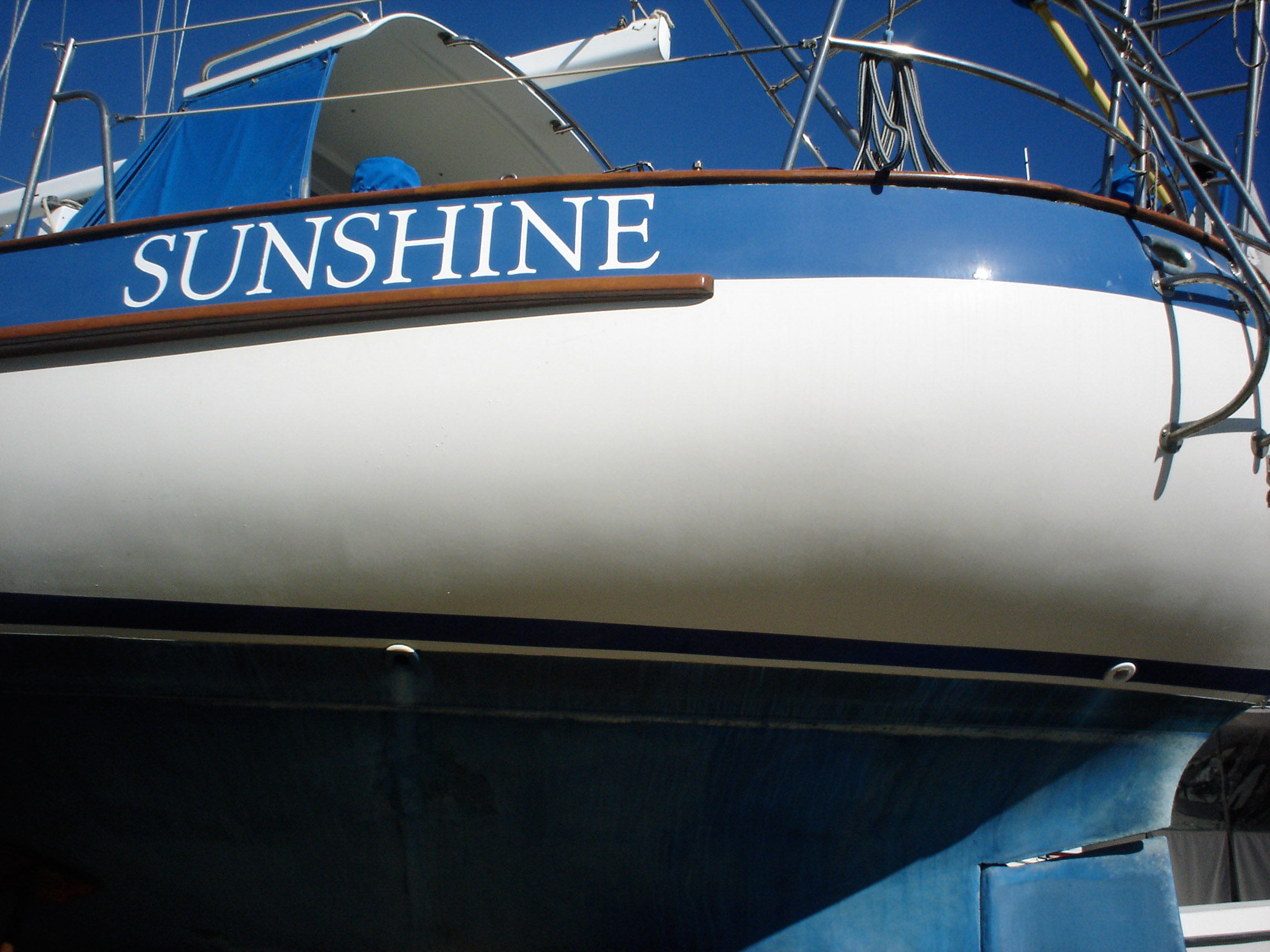
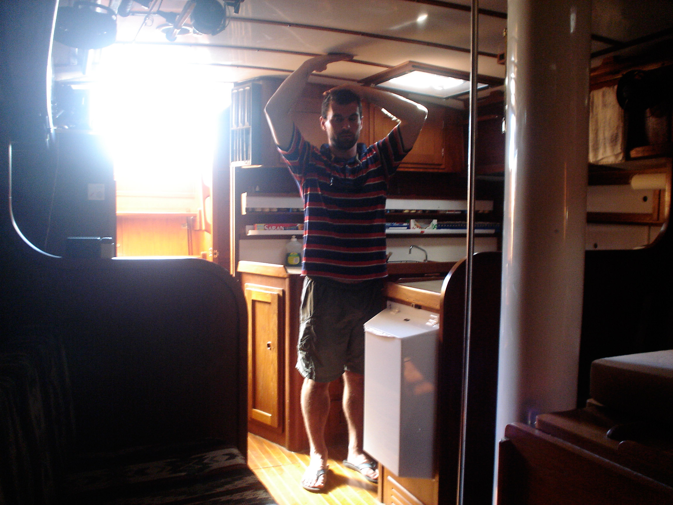
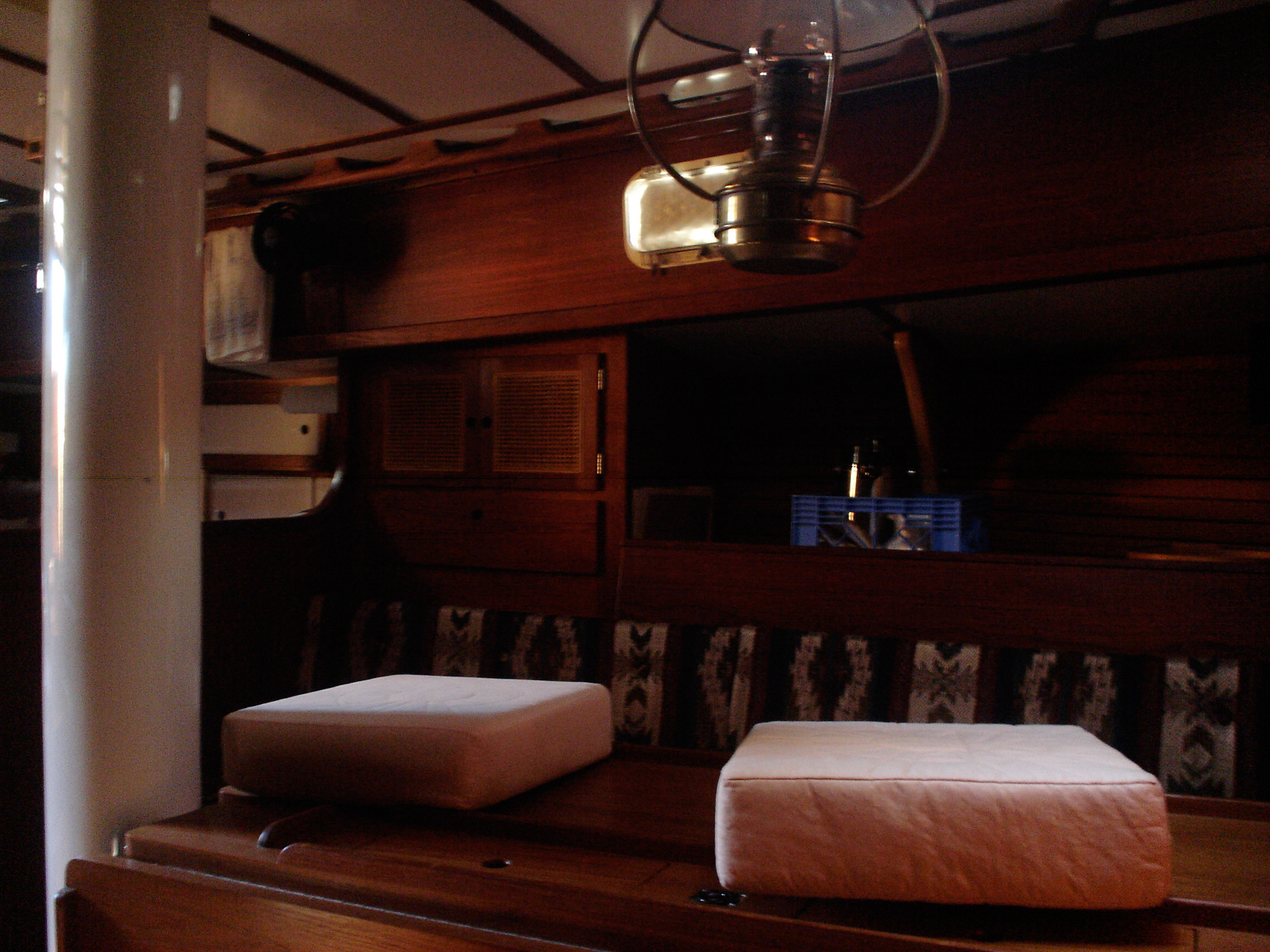
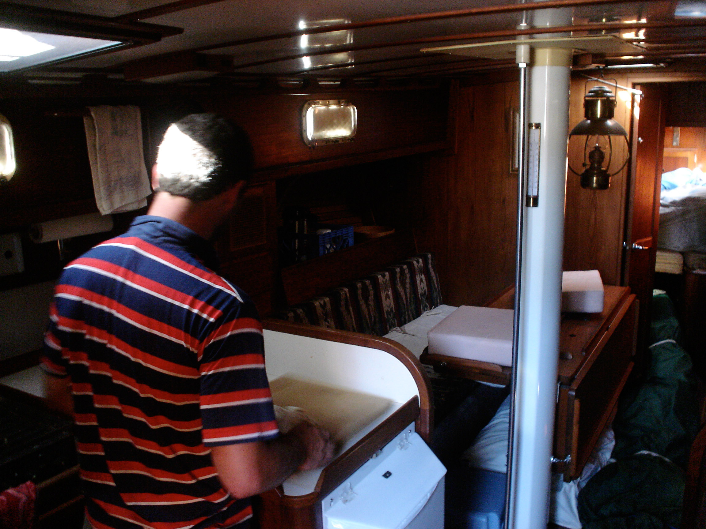
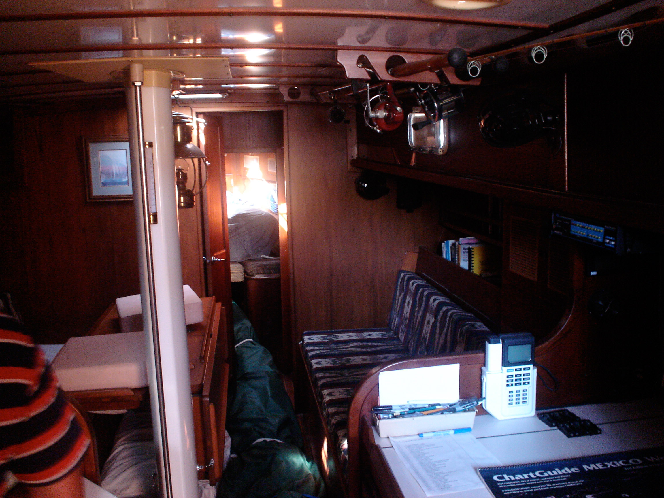
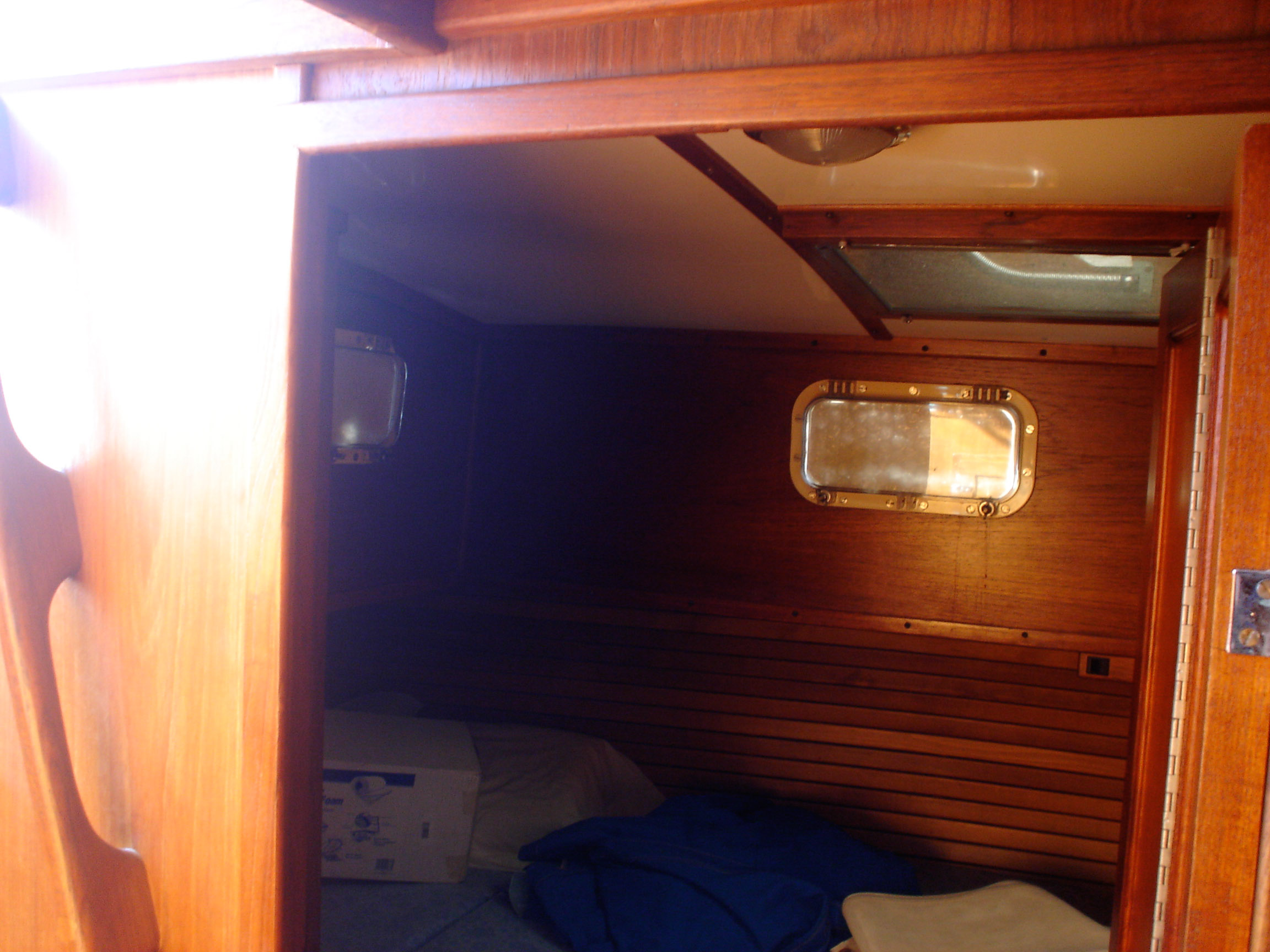
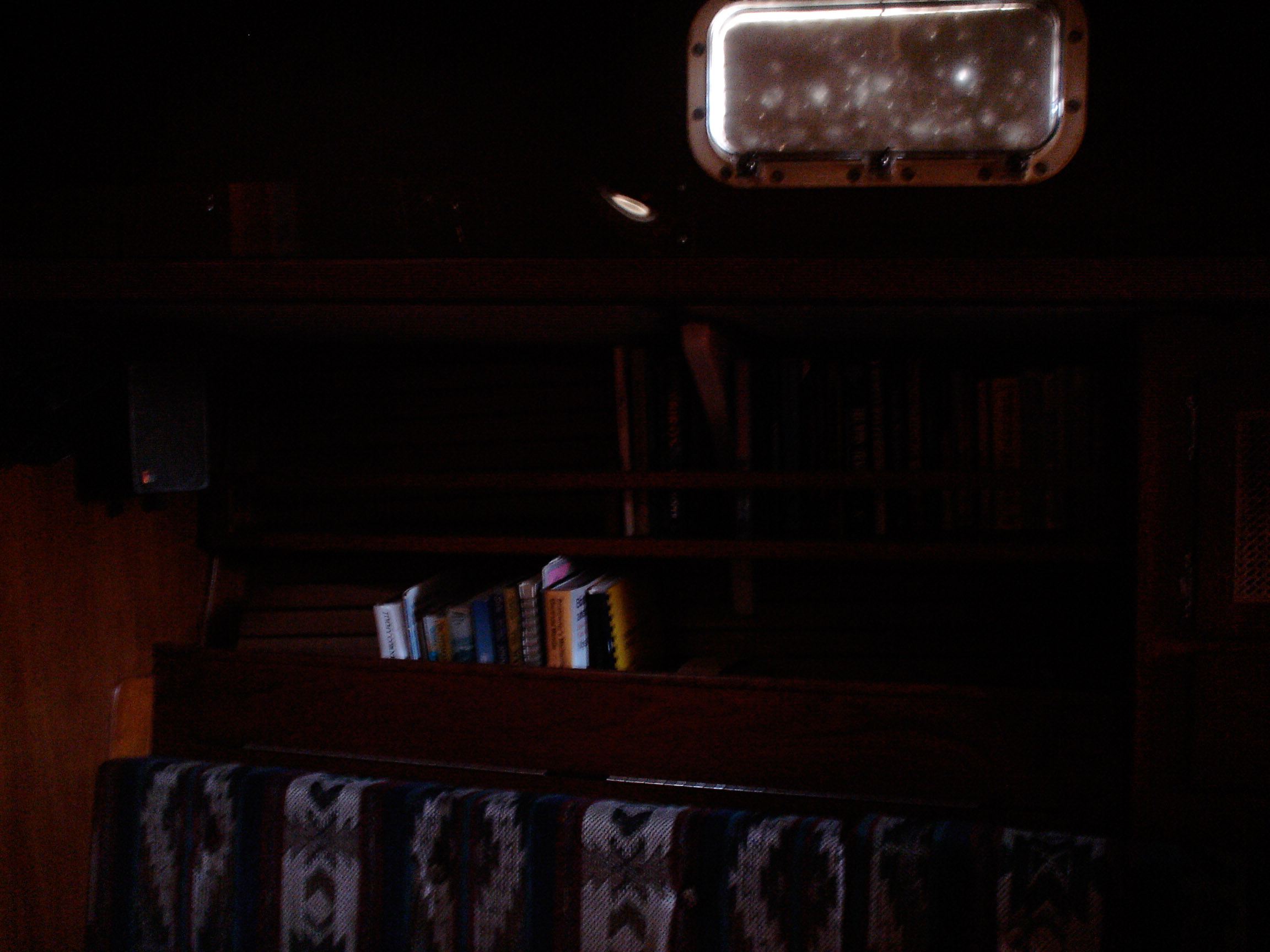
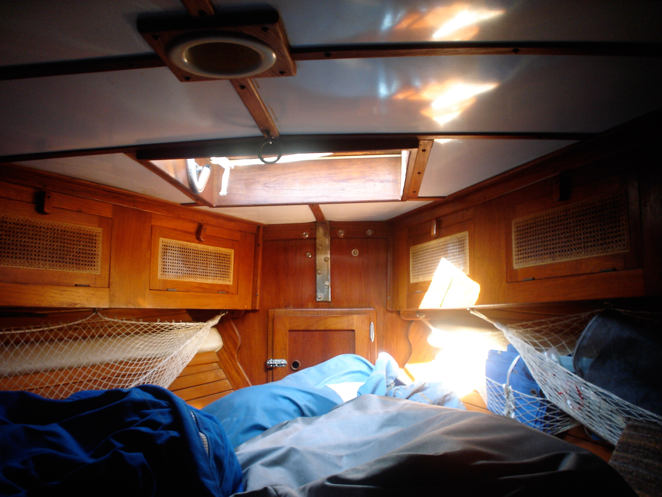
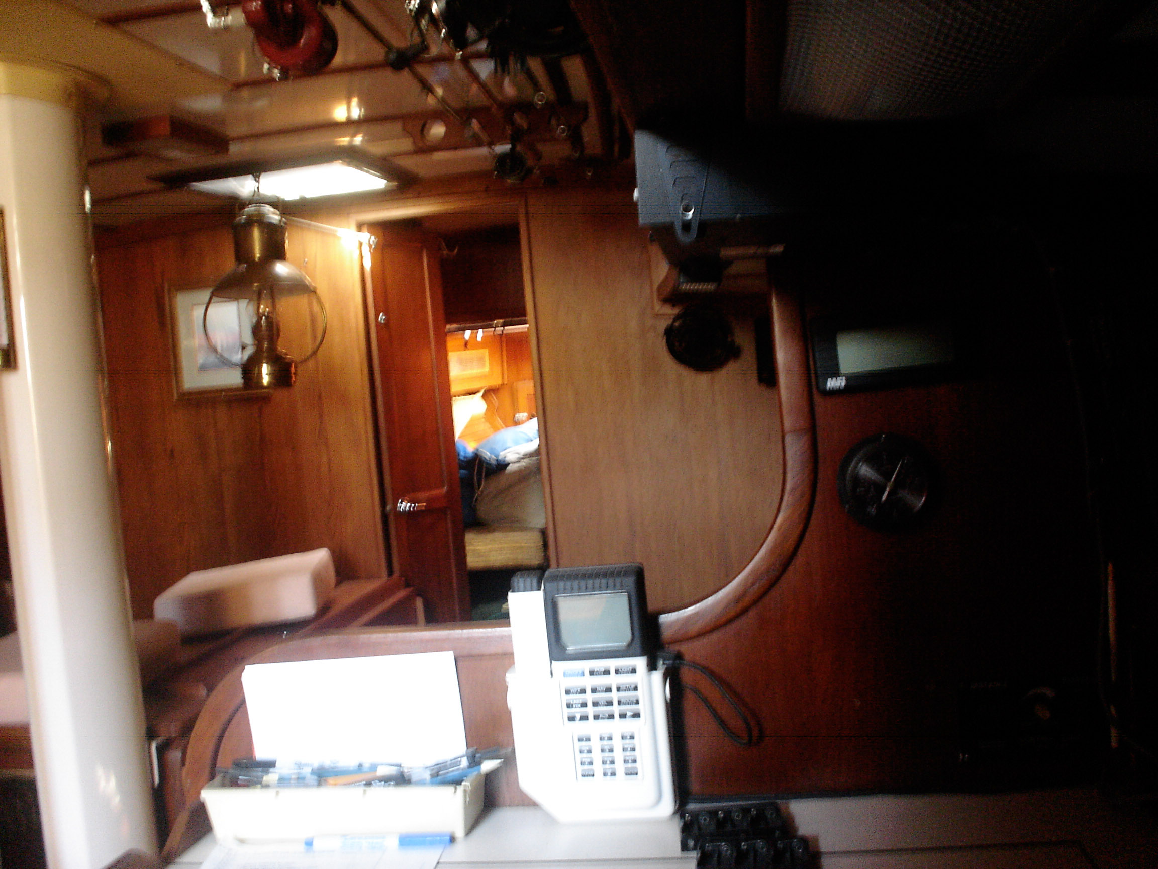
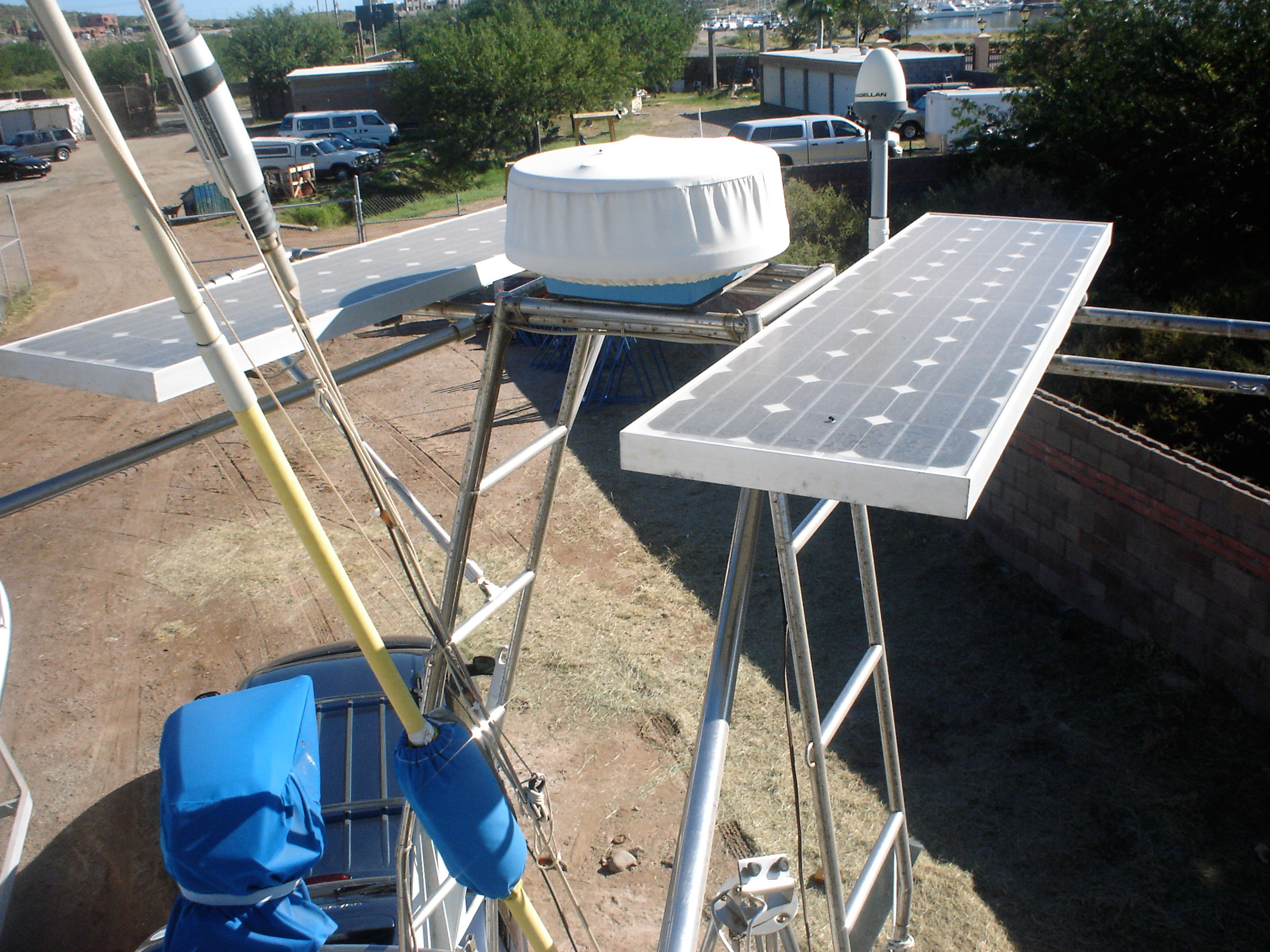
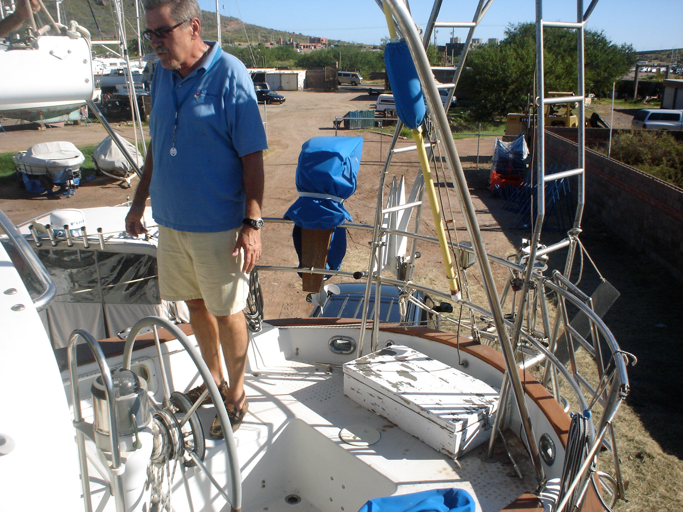
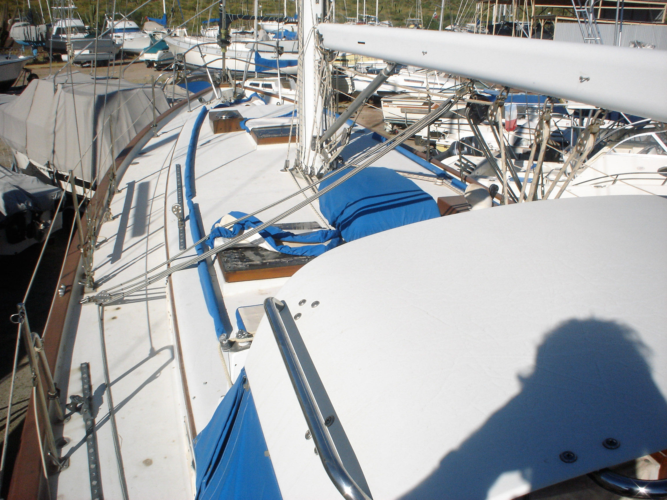
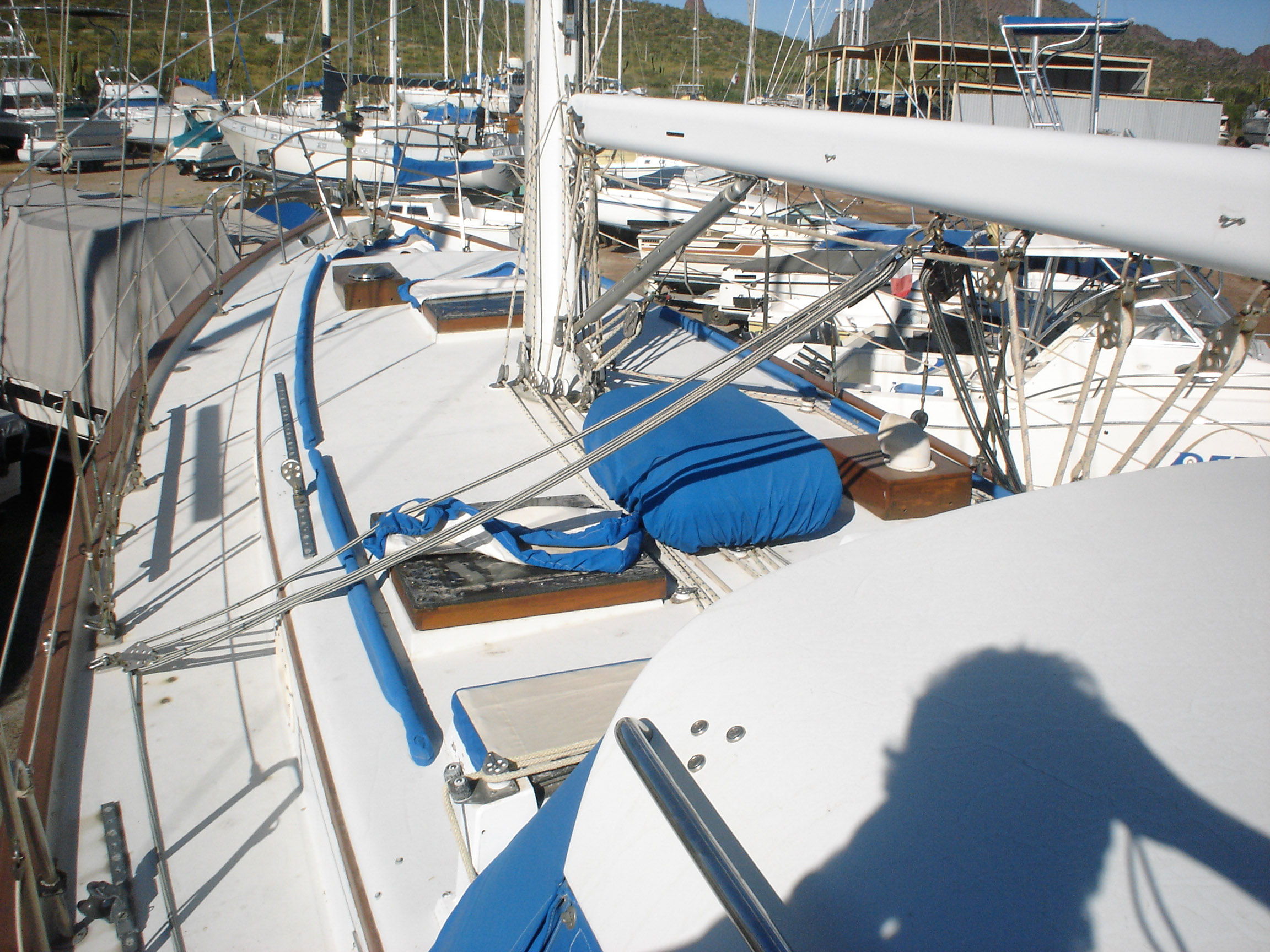
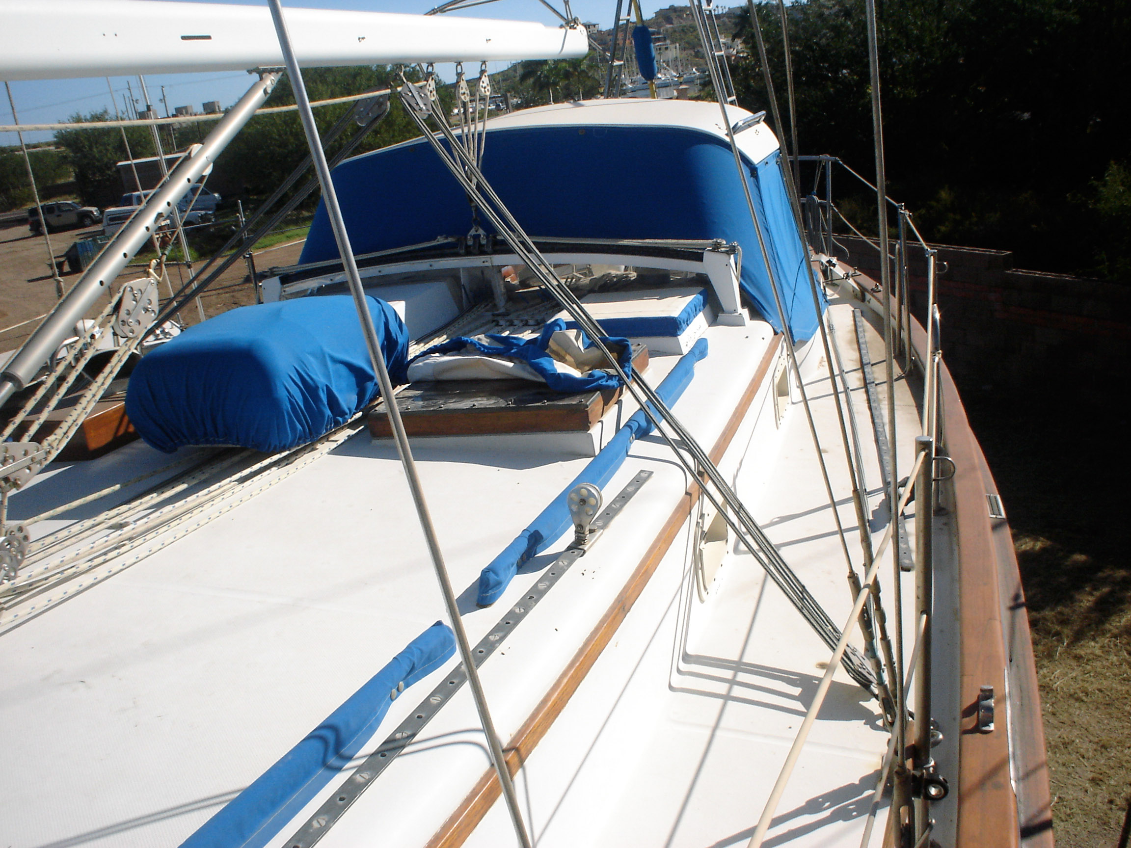
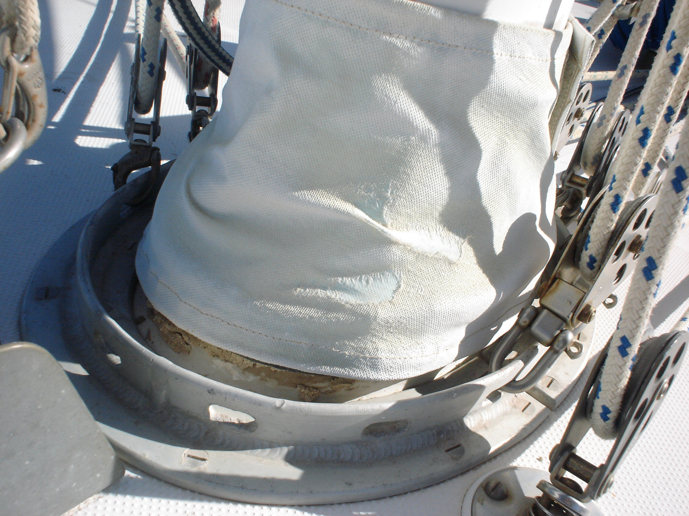
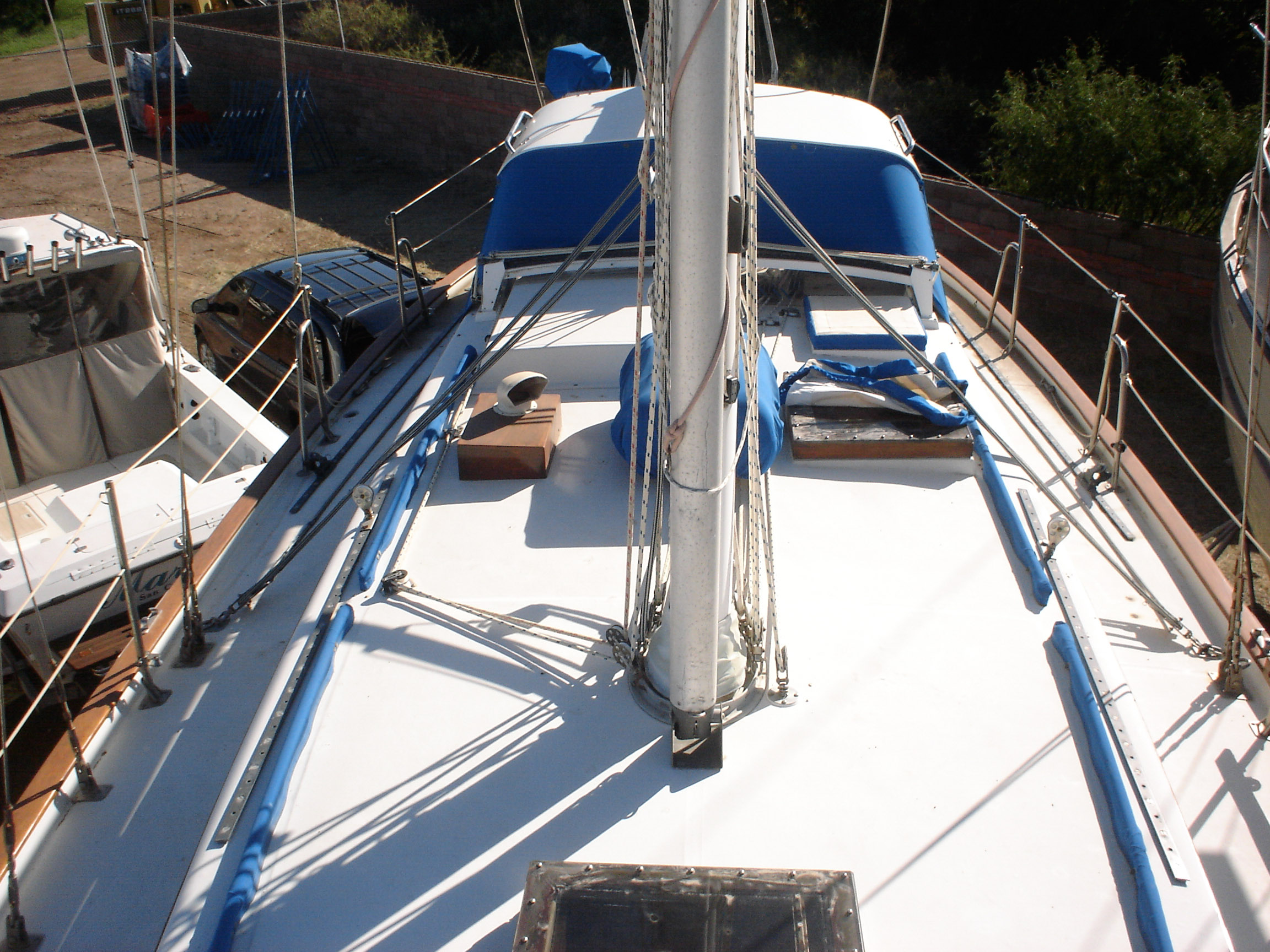
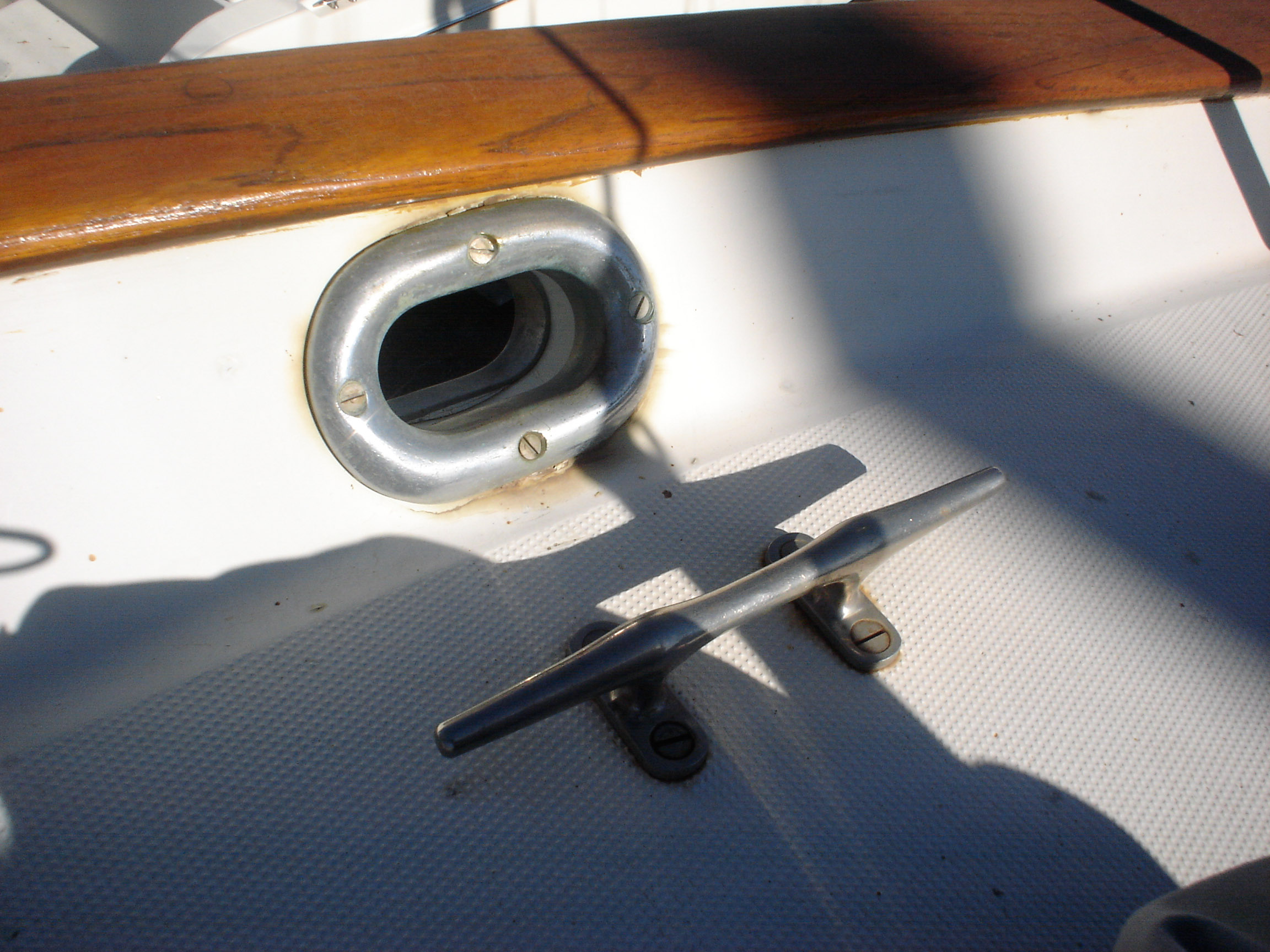
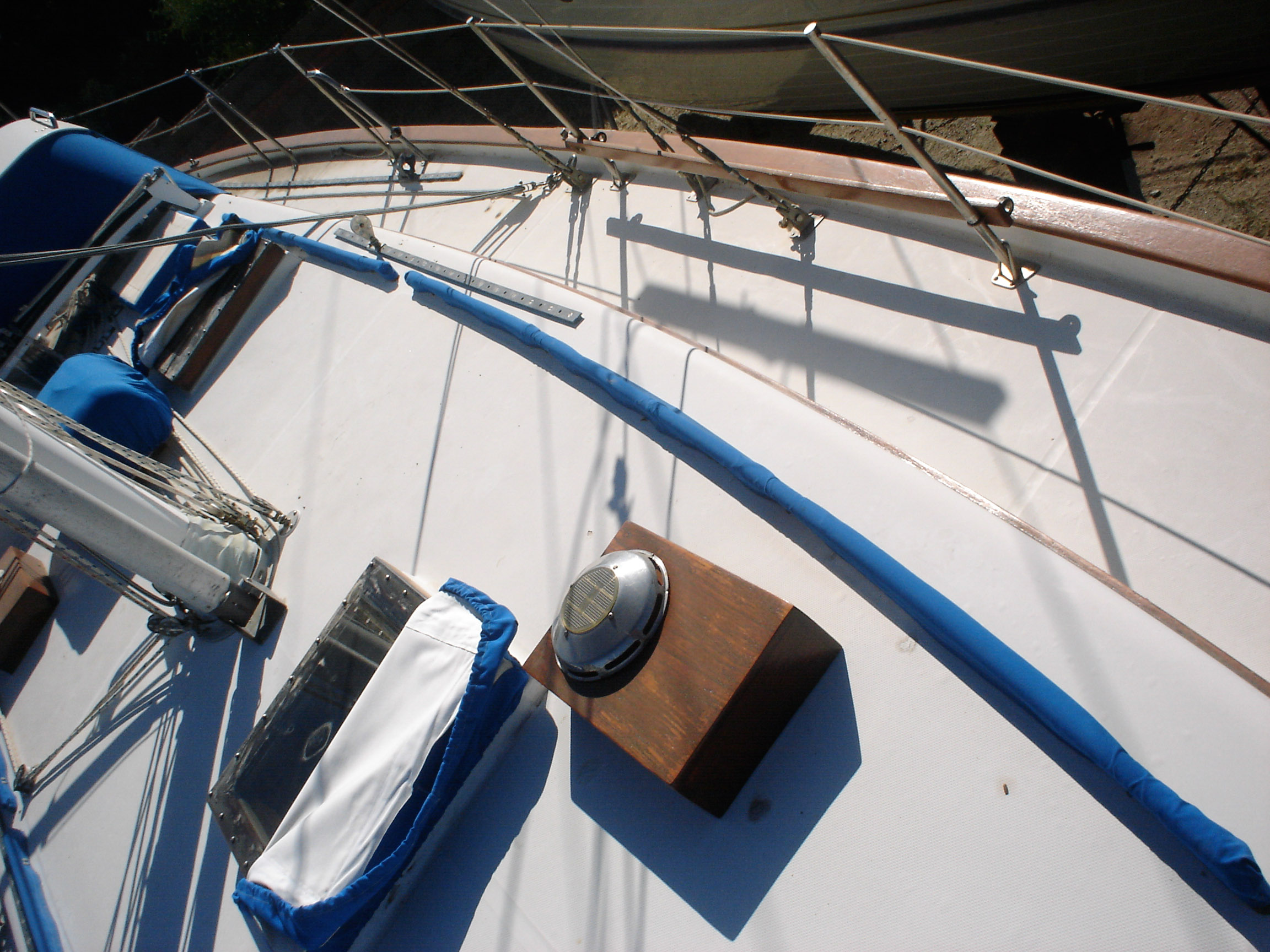
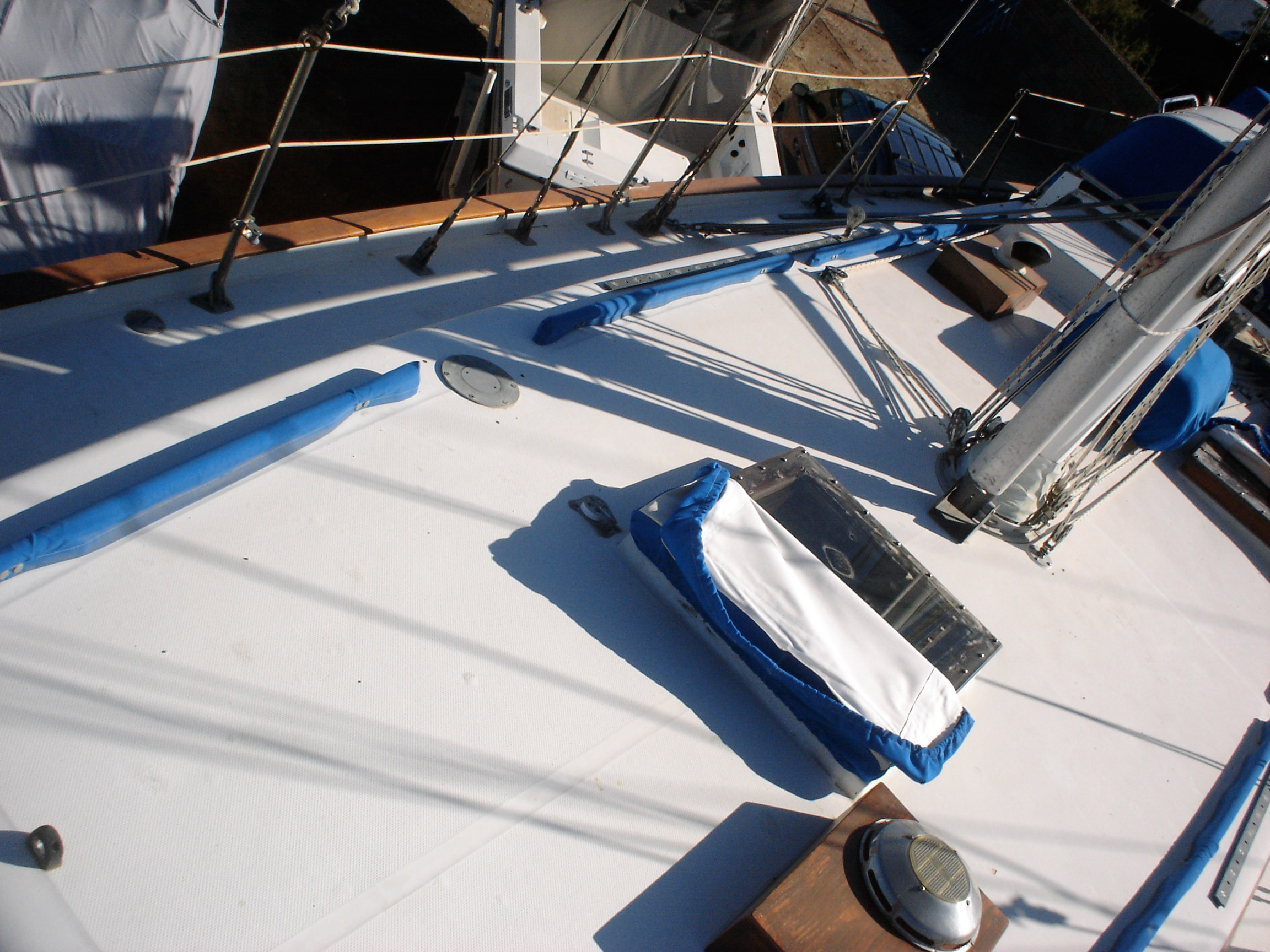
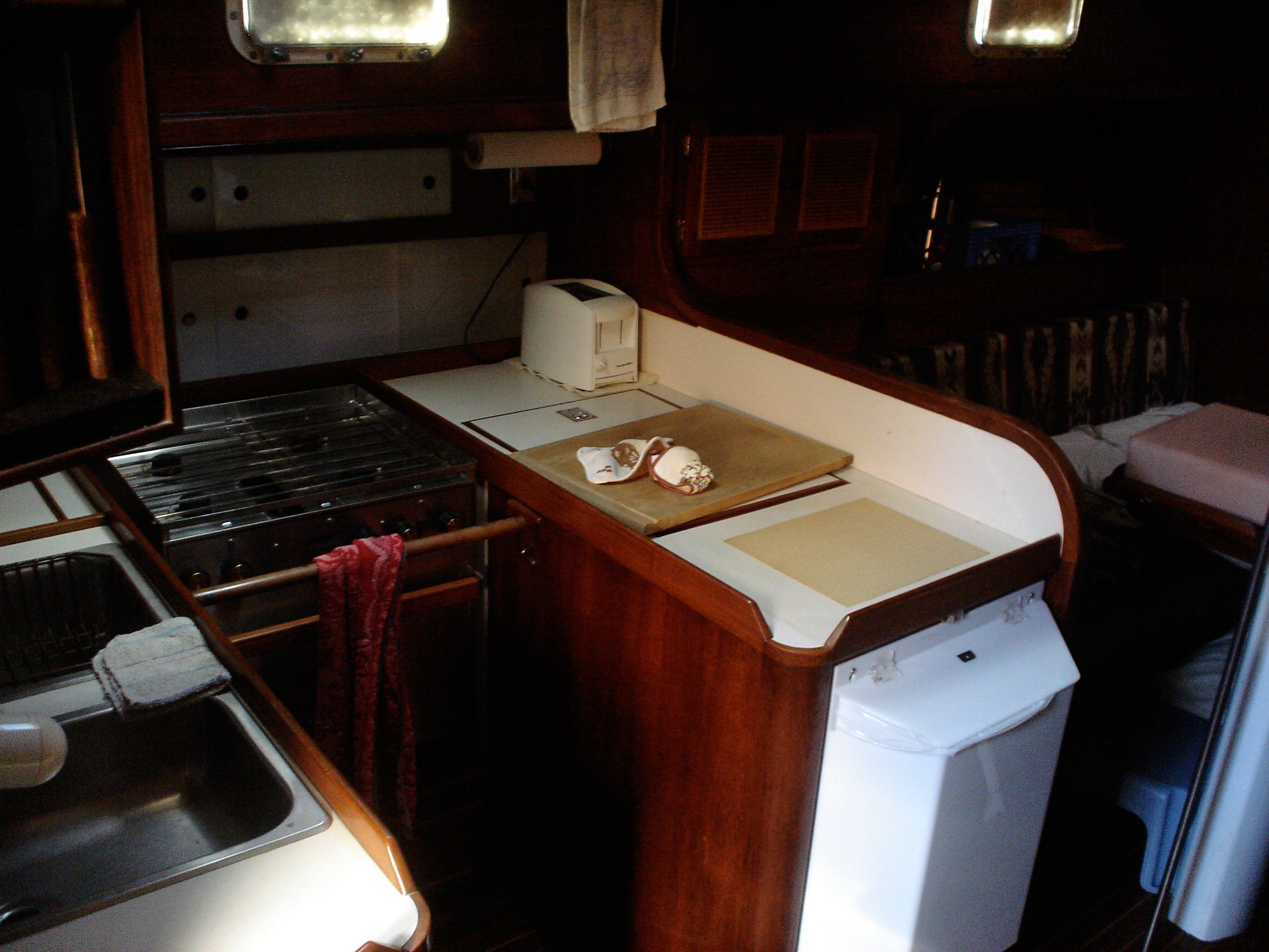
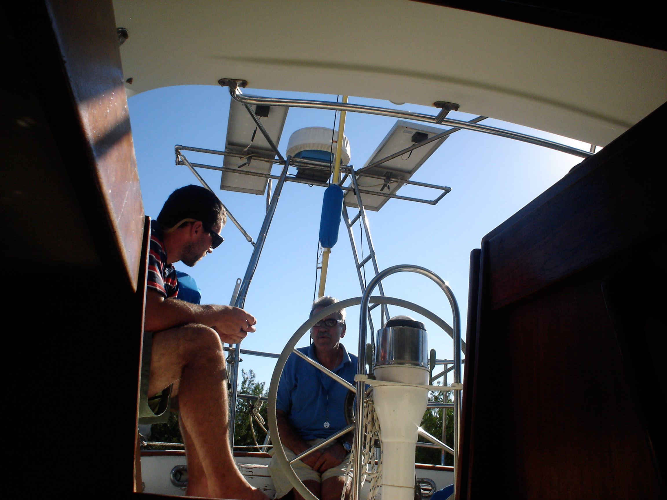
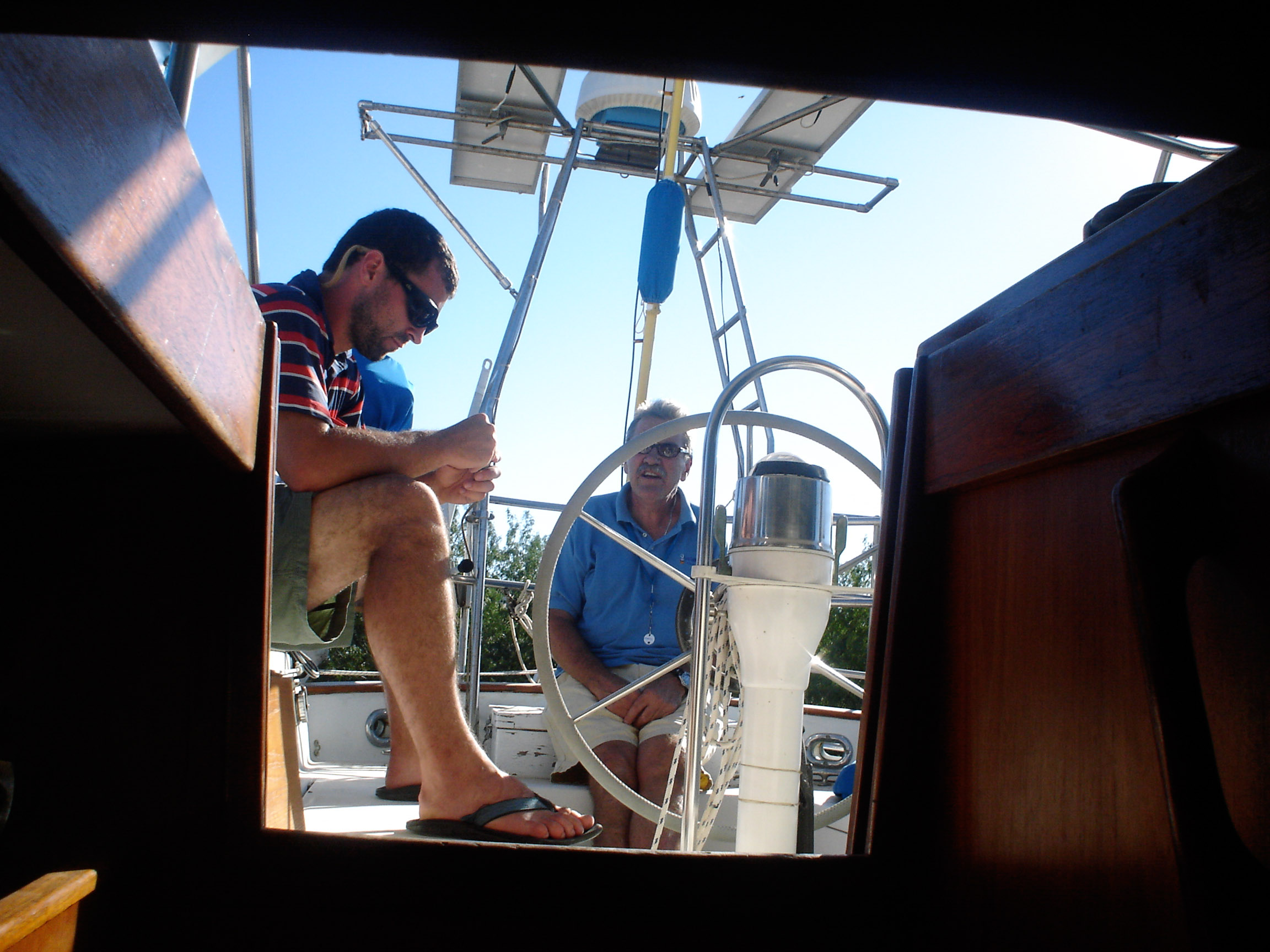
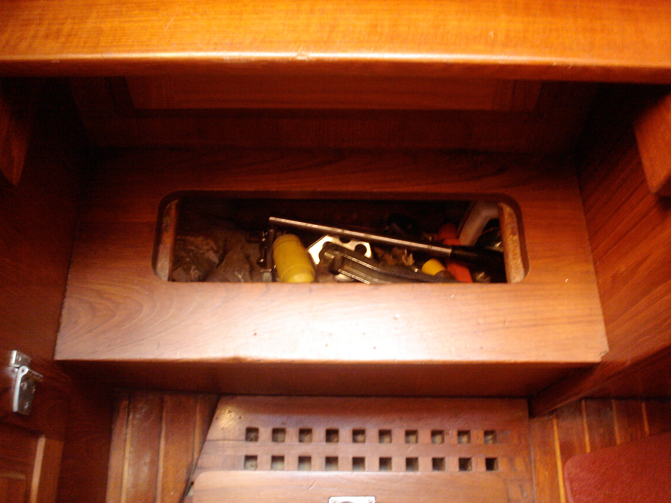
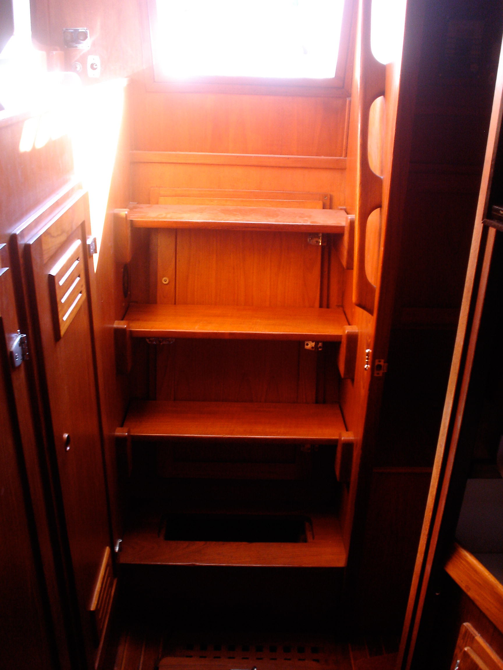
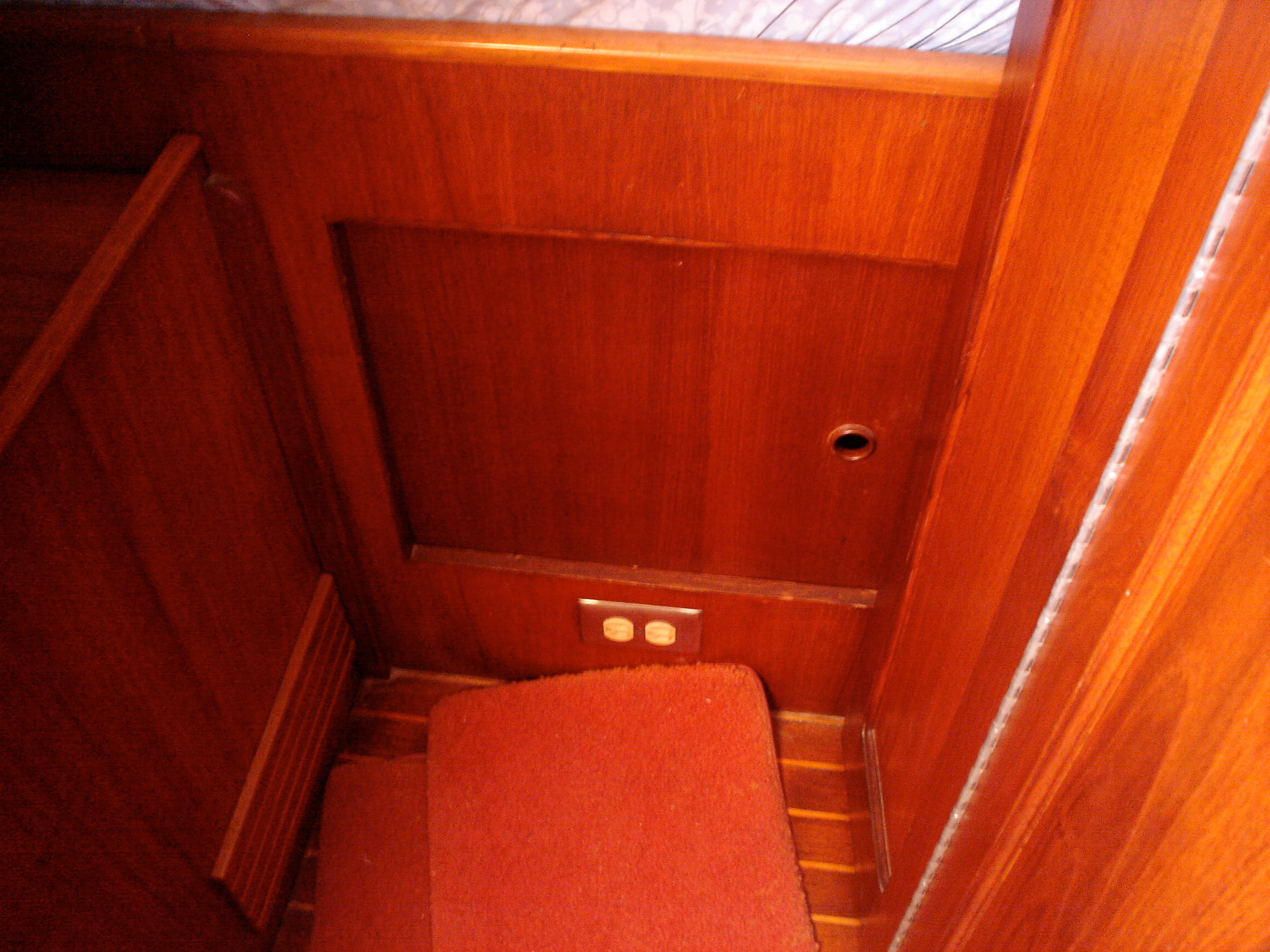
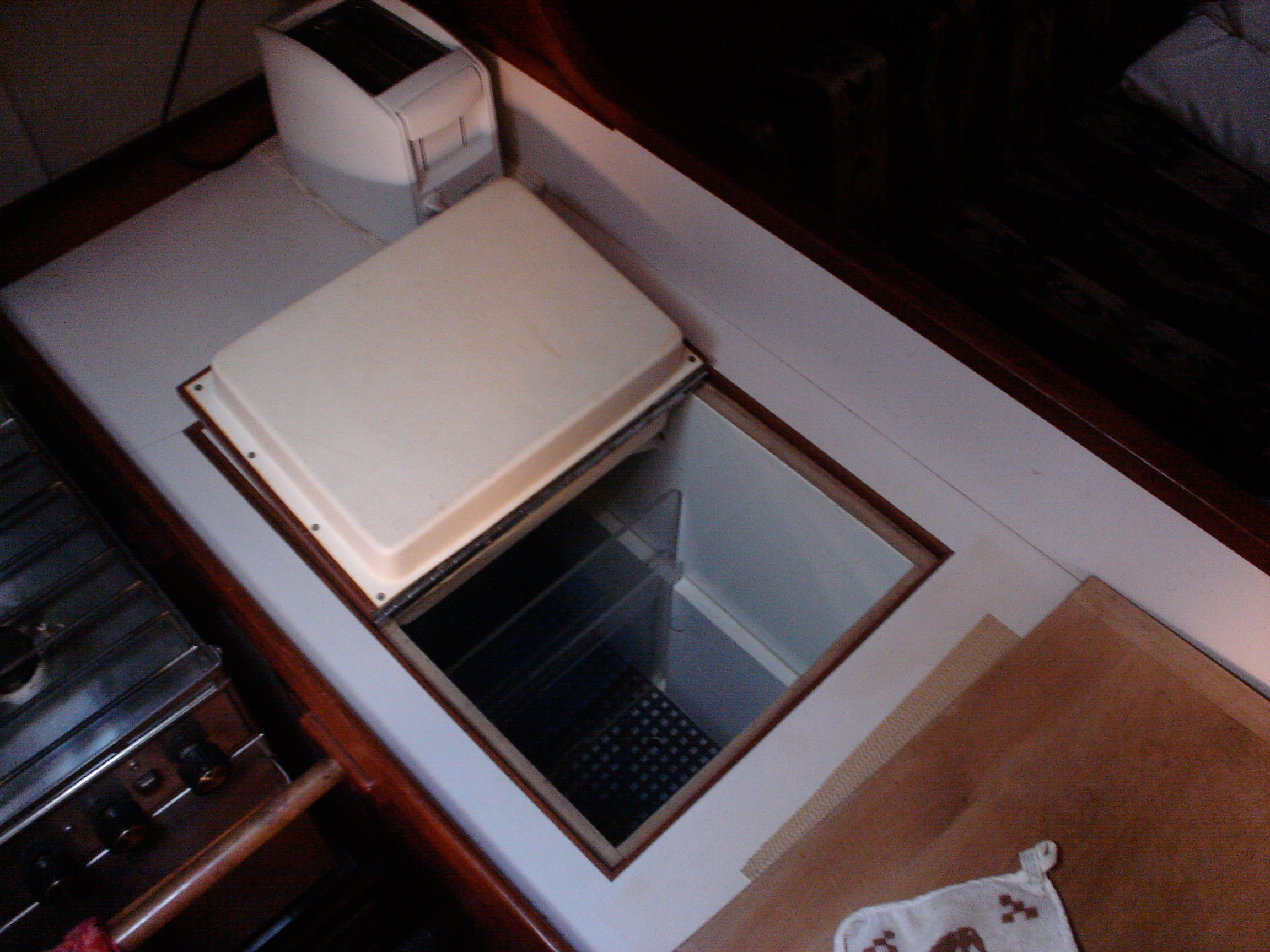
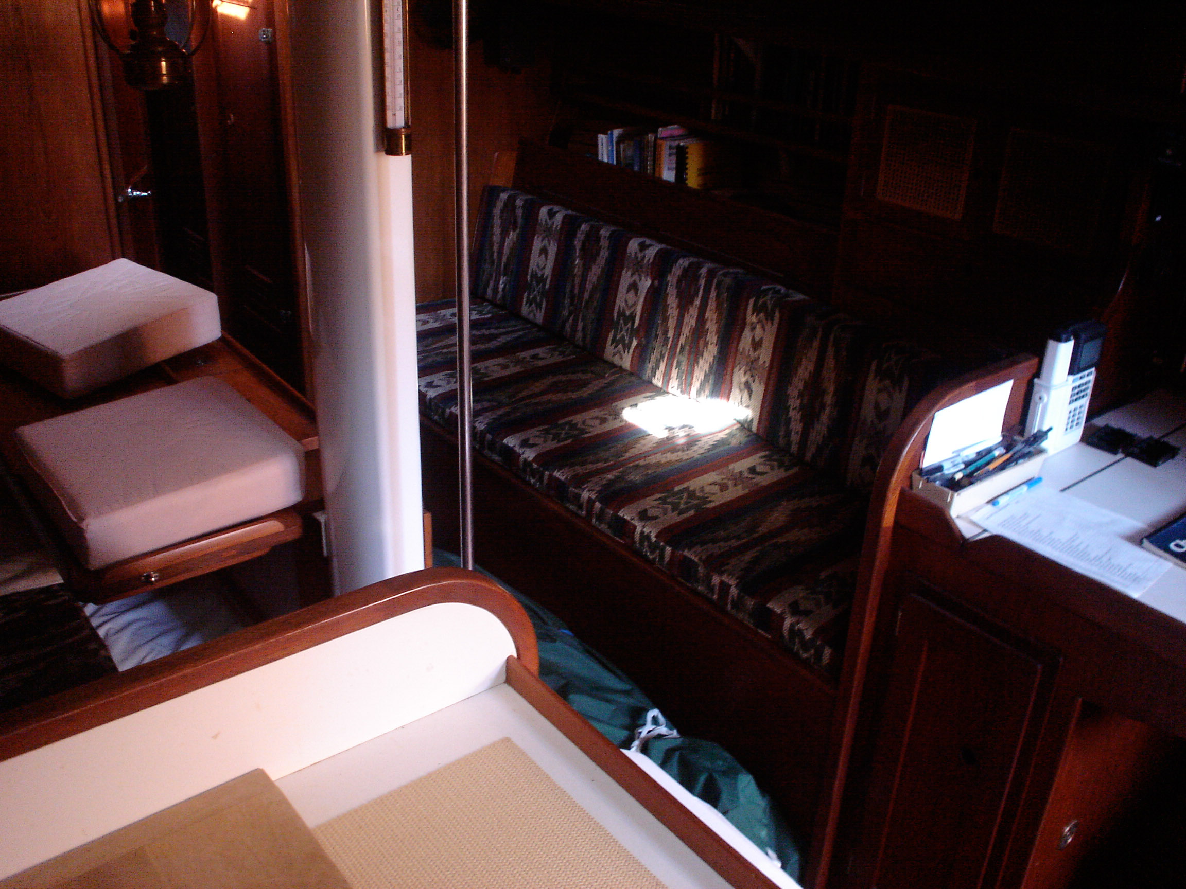
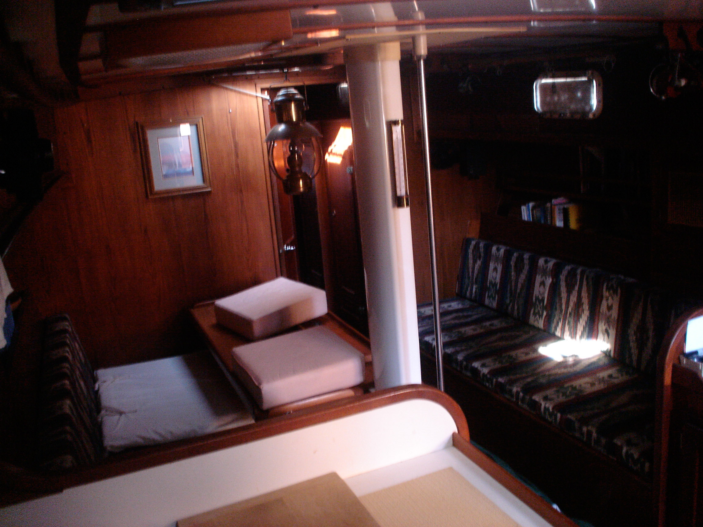
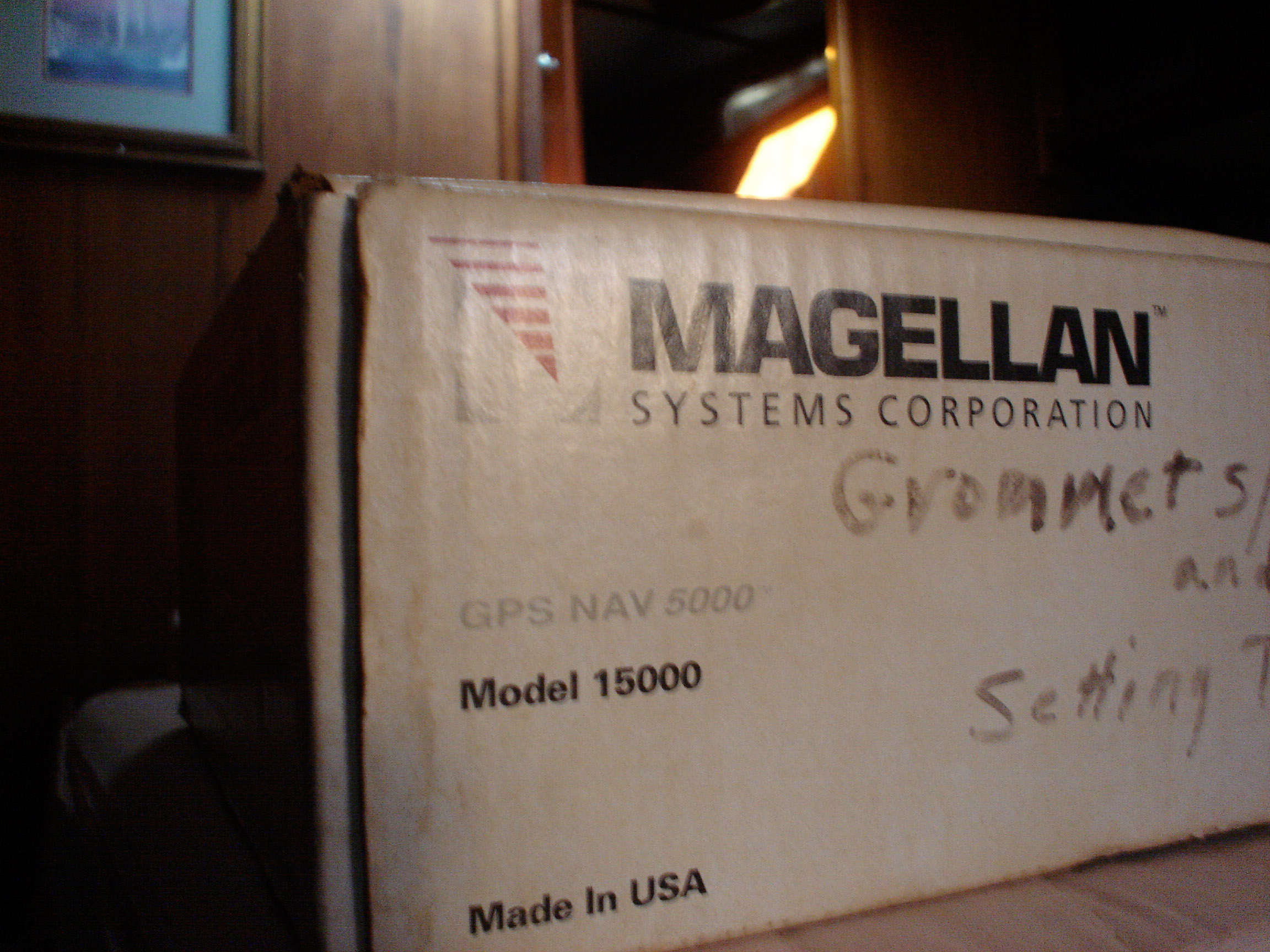
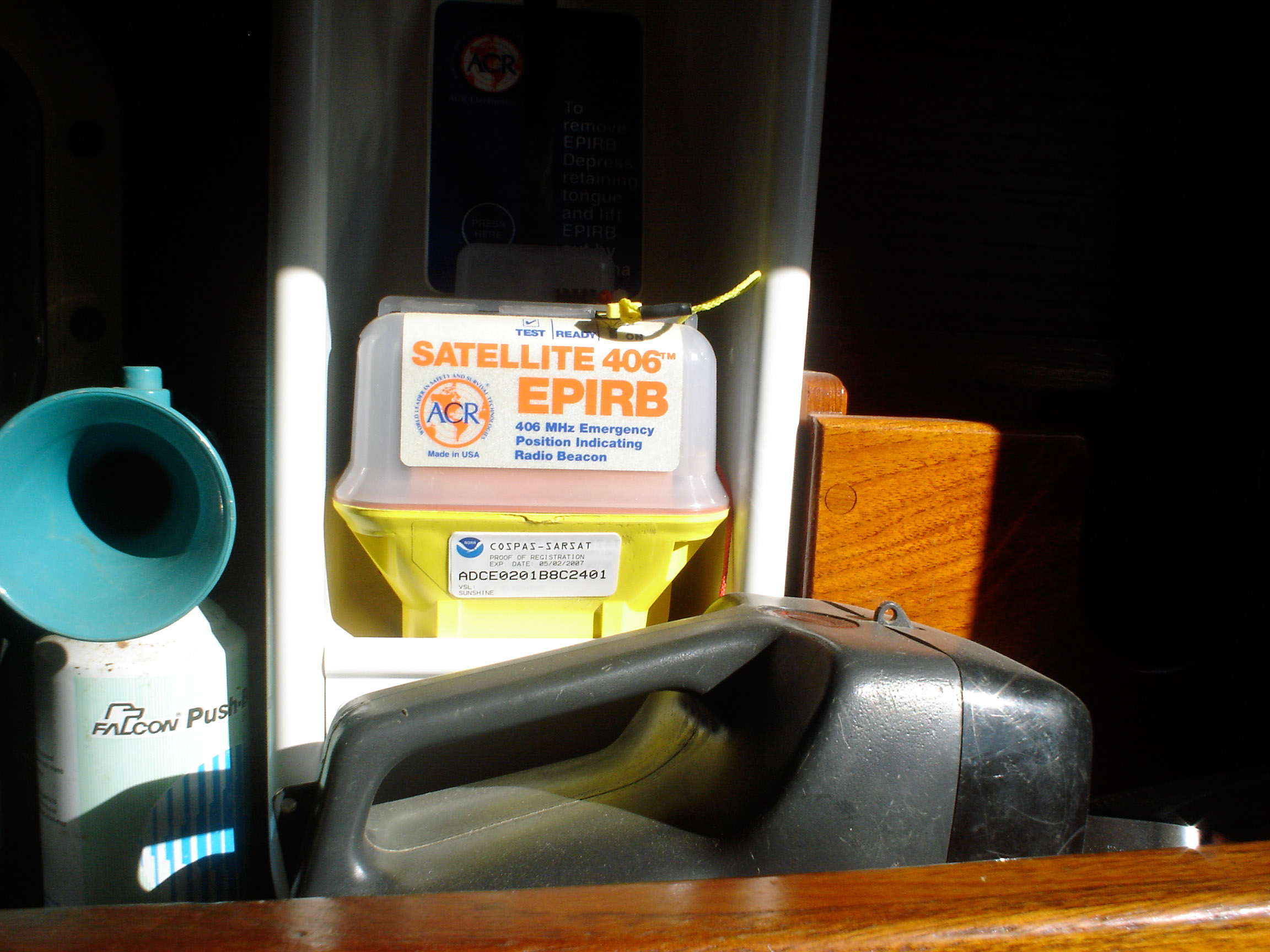
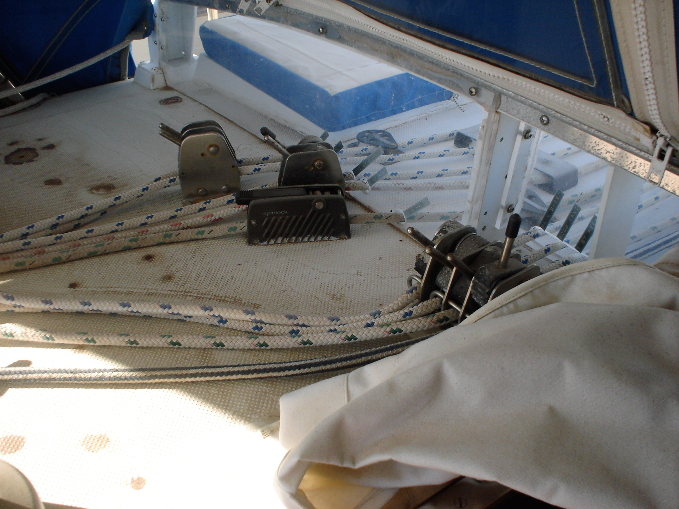
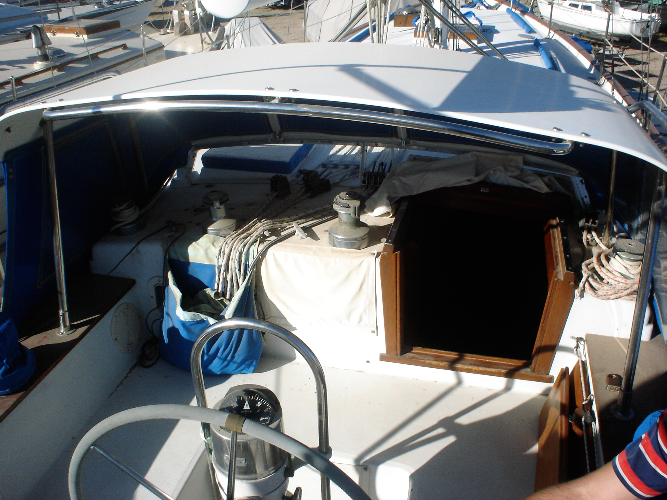
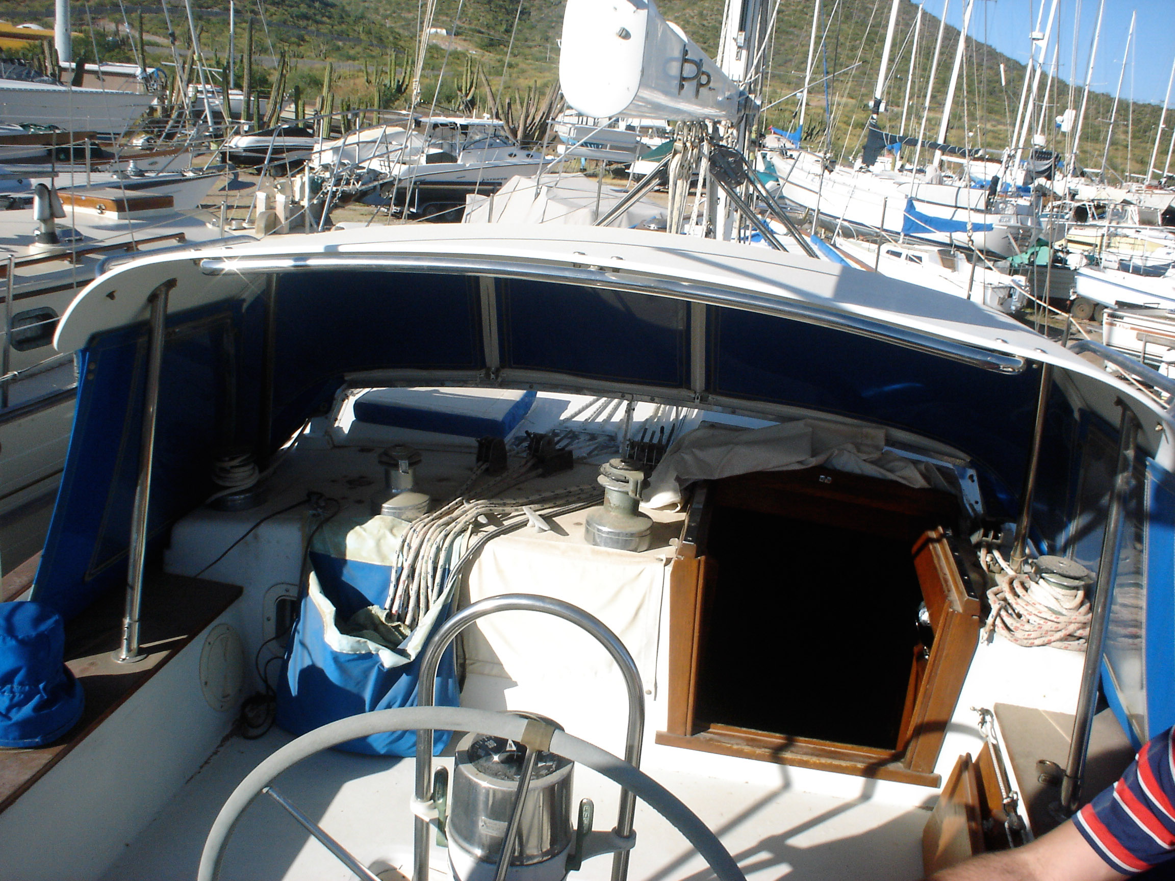
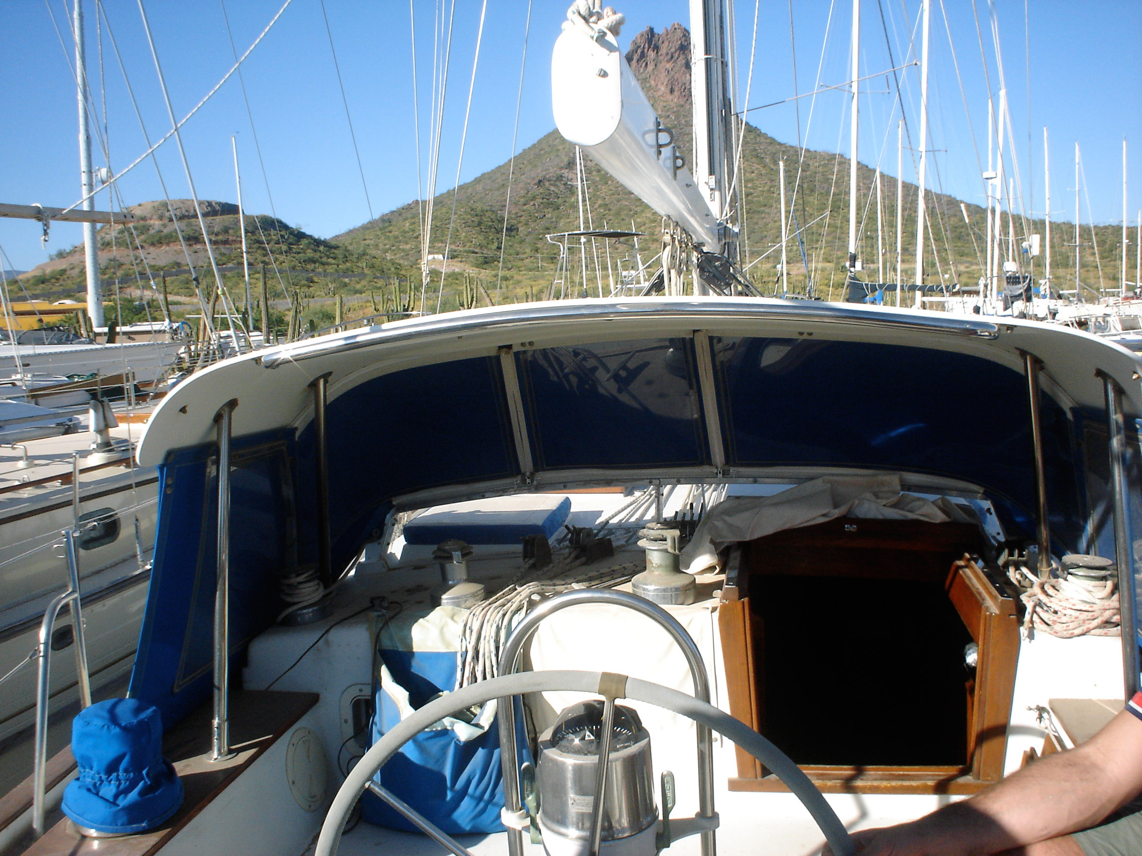
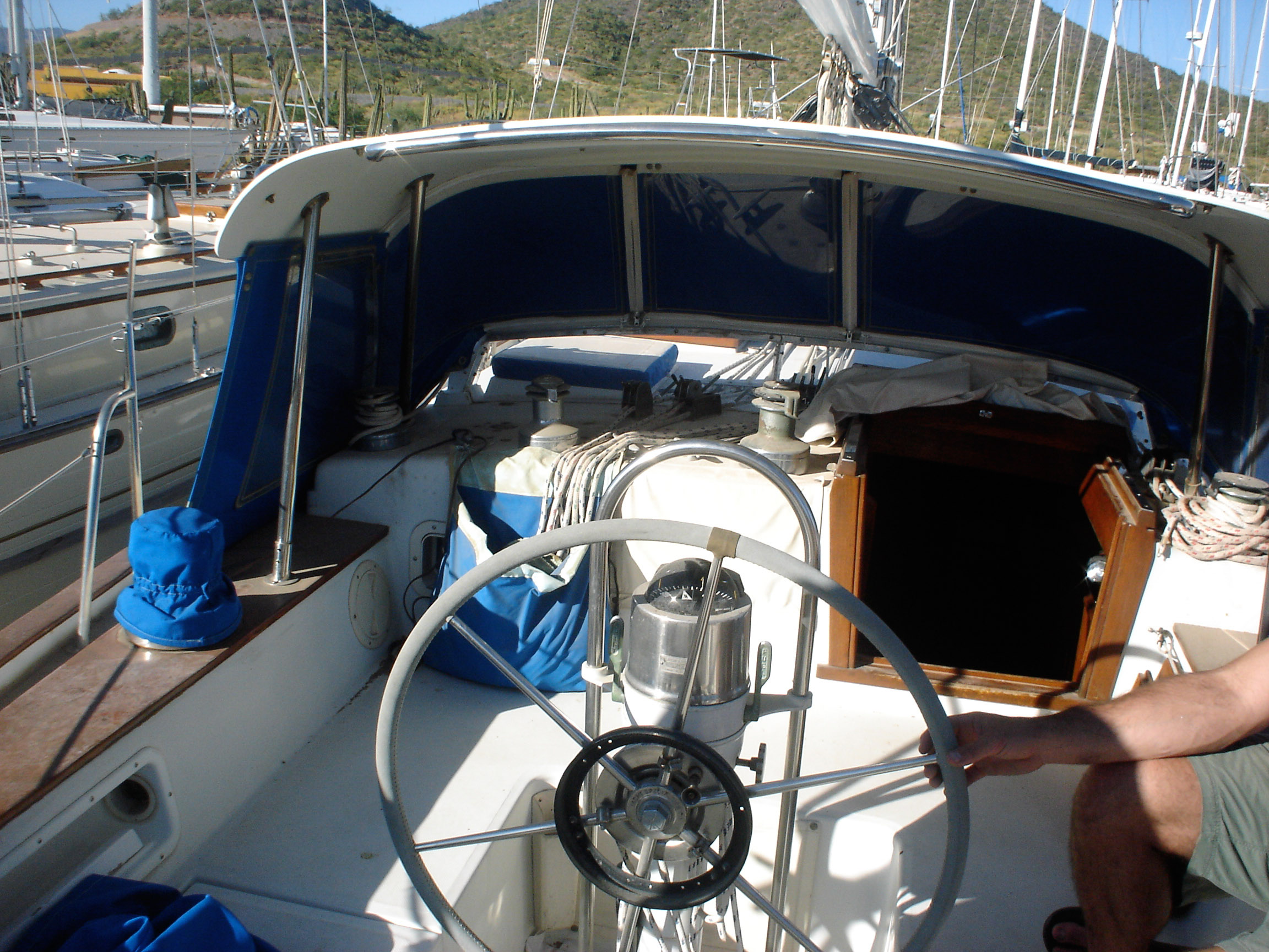
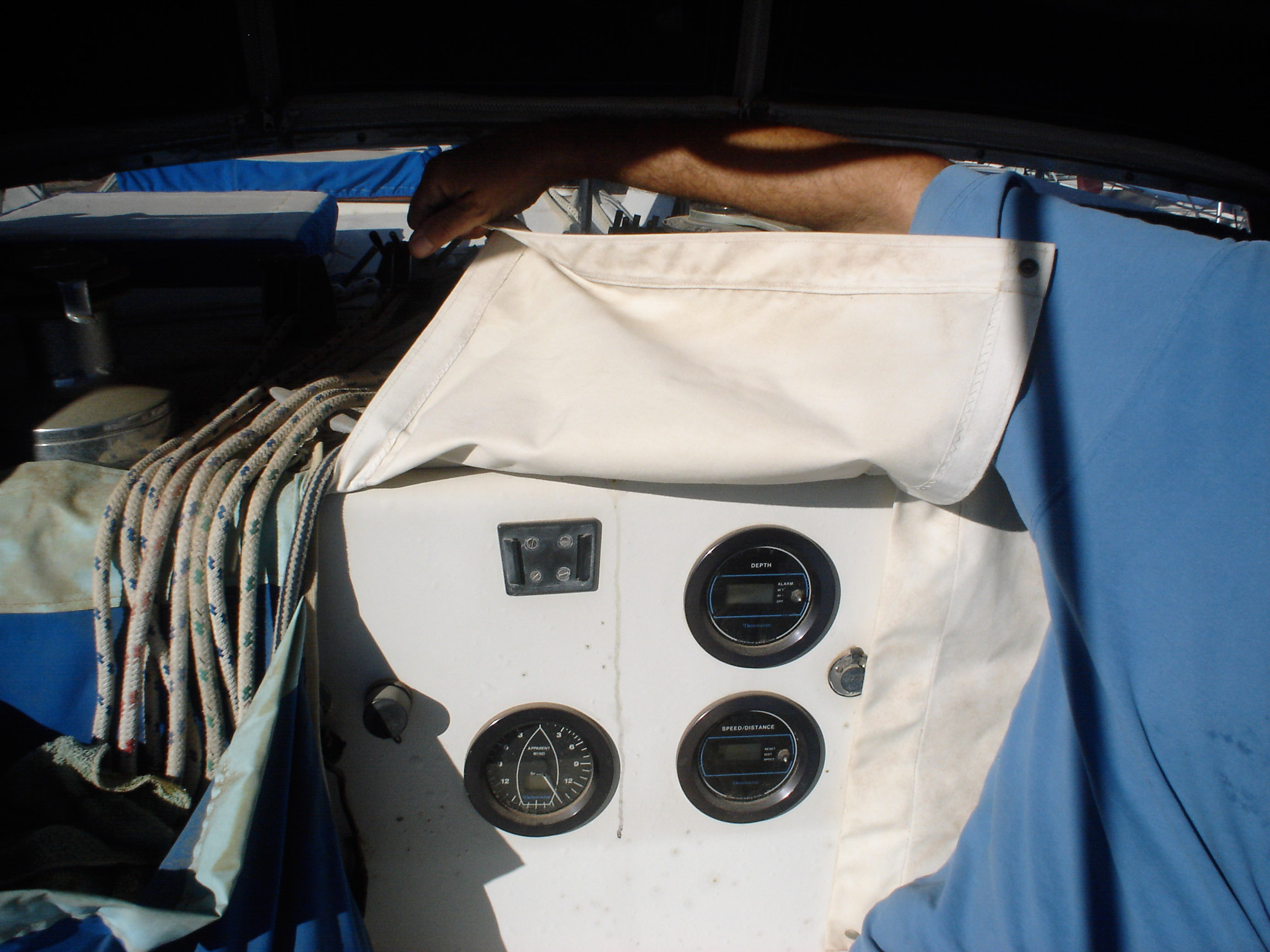
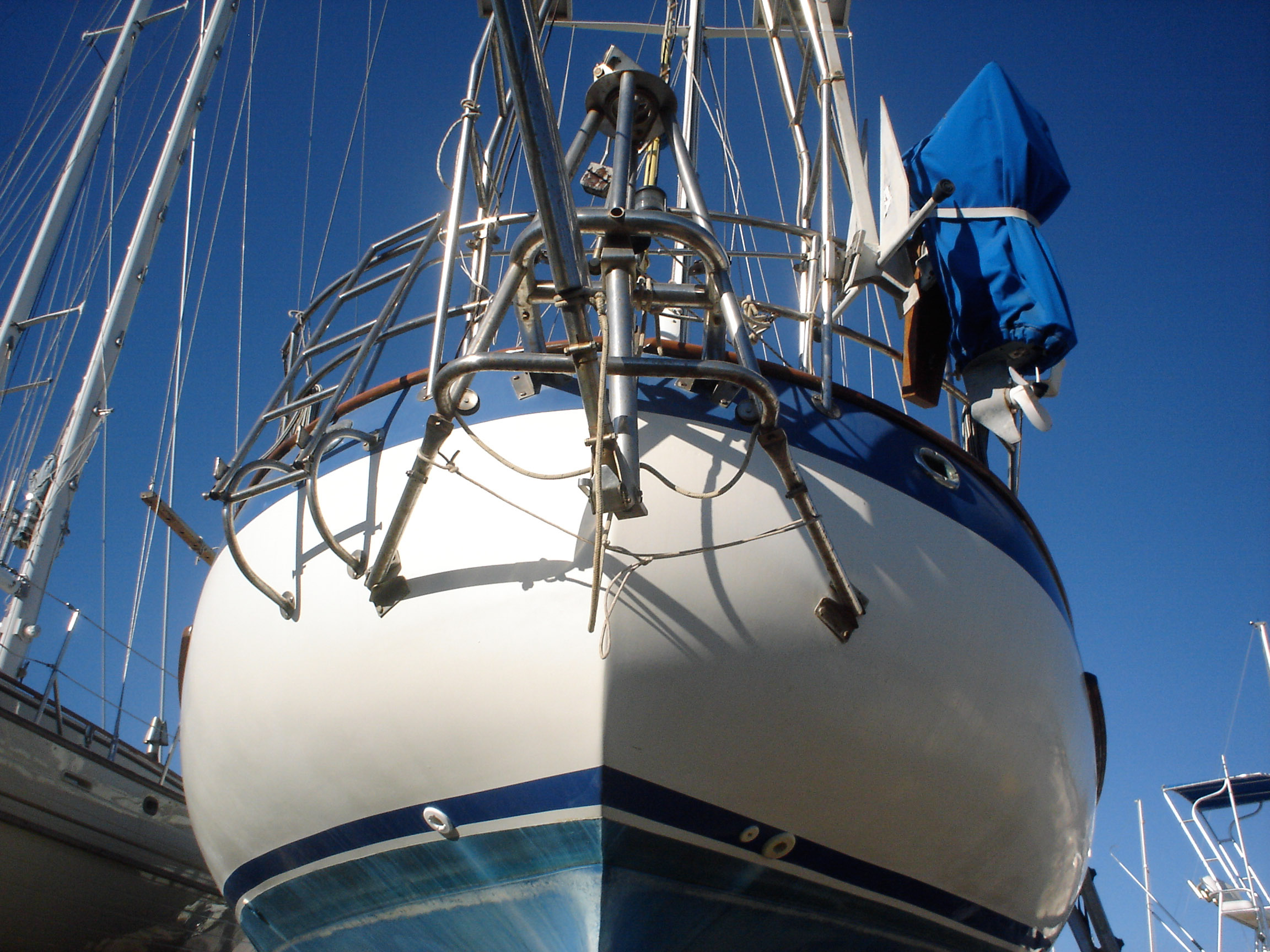
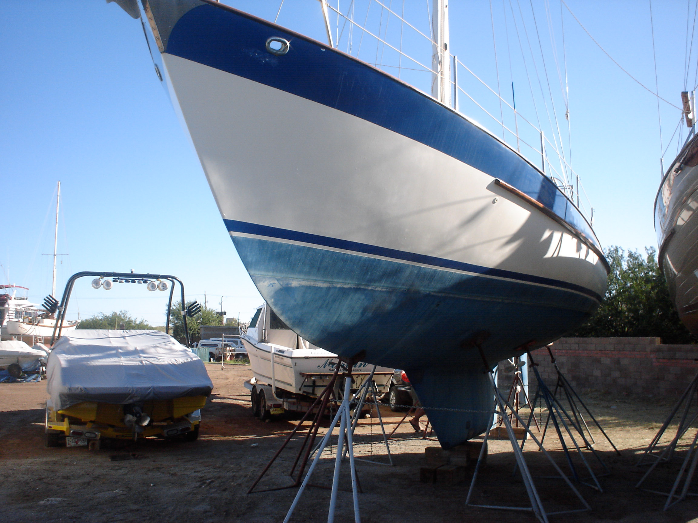
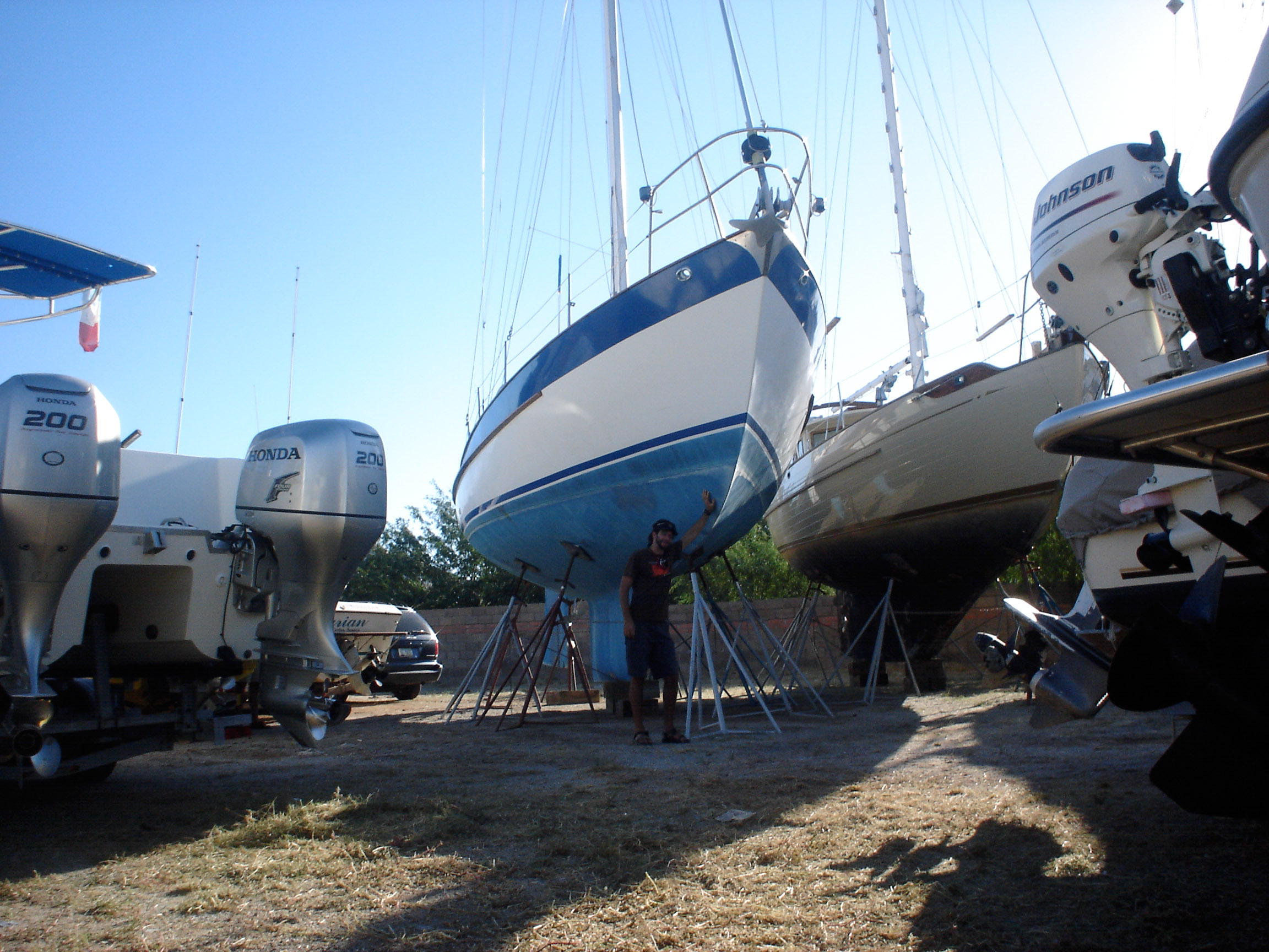
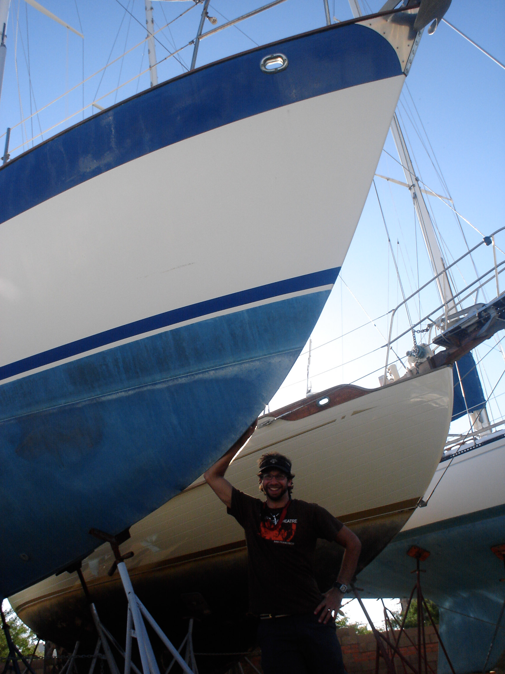
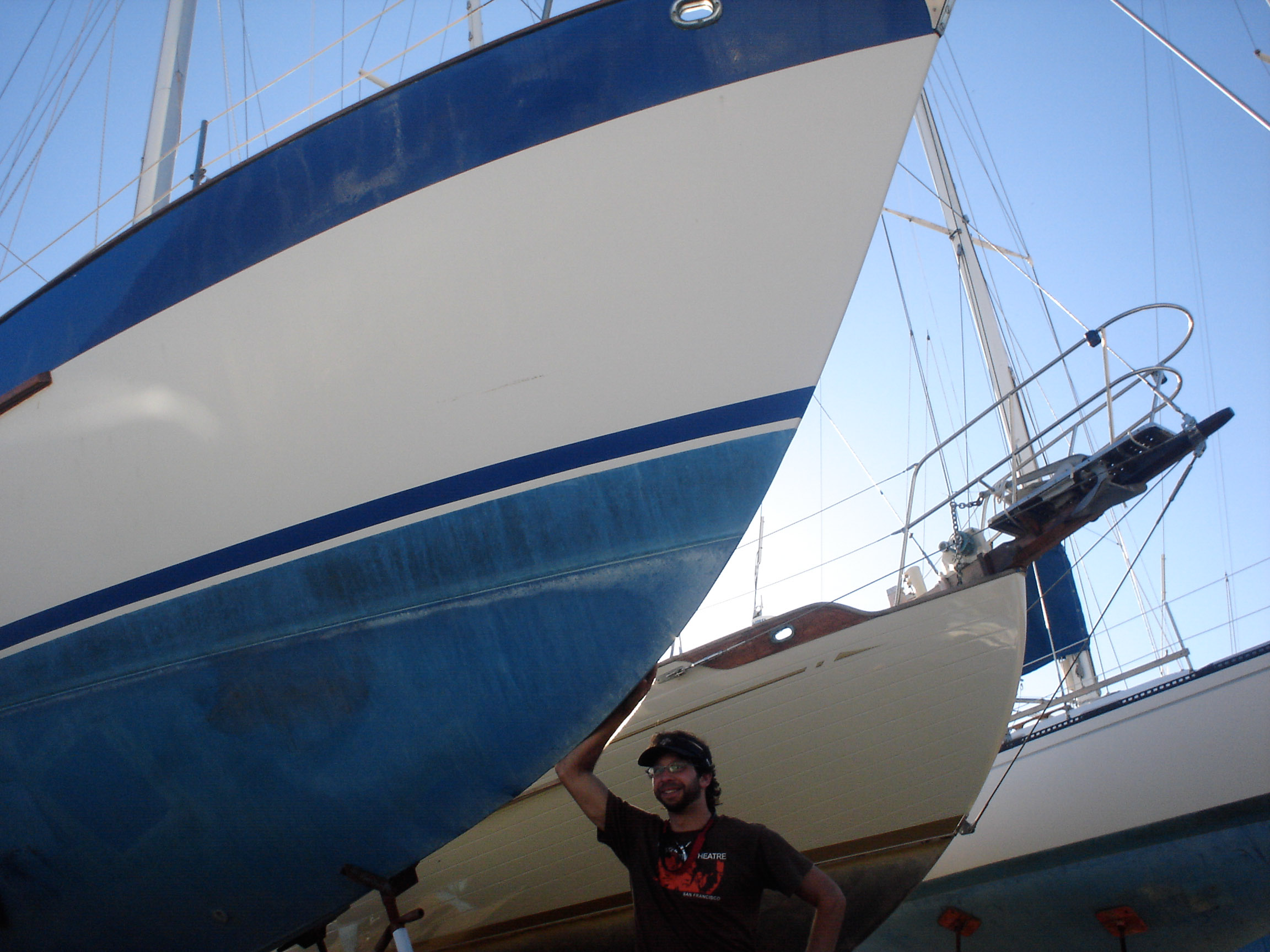
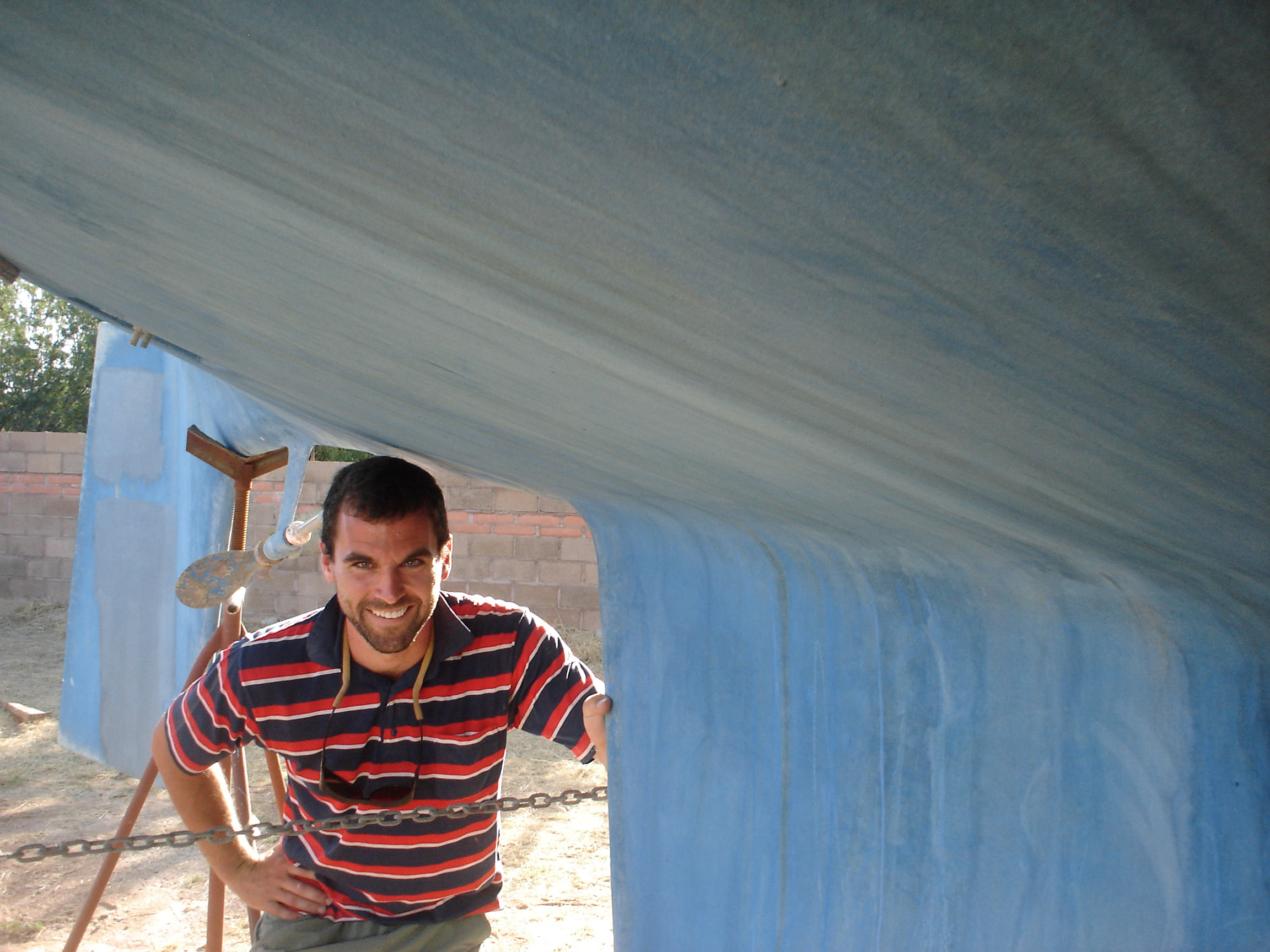
First Pictures, pre-purchase
Jonny went to Mexico with Jeff to check out the boat, took these pictures.