Category: Hull

  • knees (part 3)

    See knees part 1 and knees part 2.

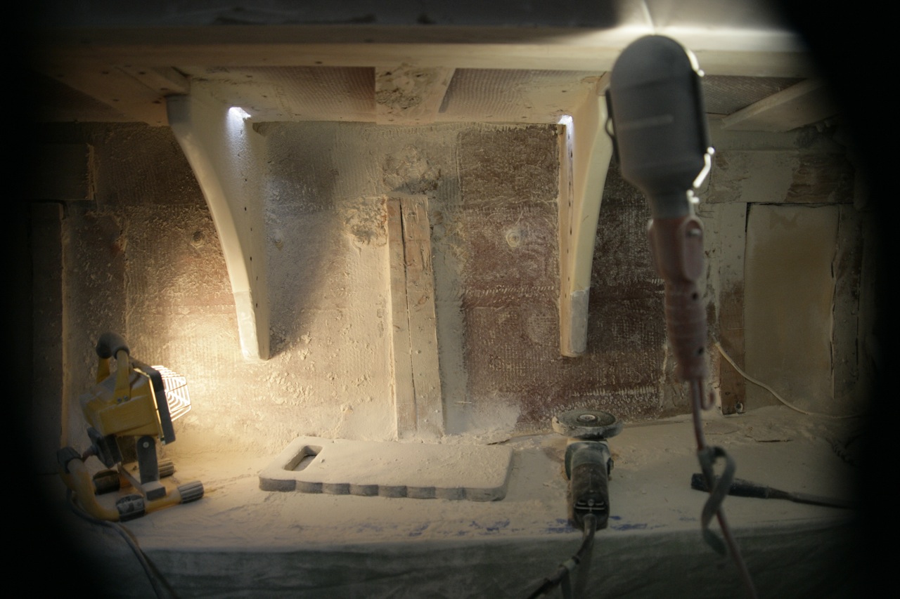
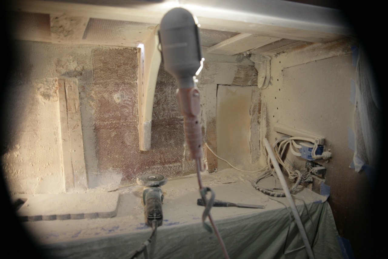
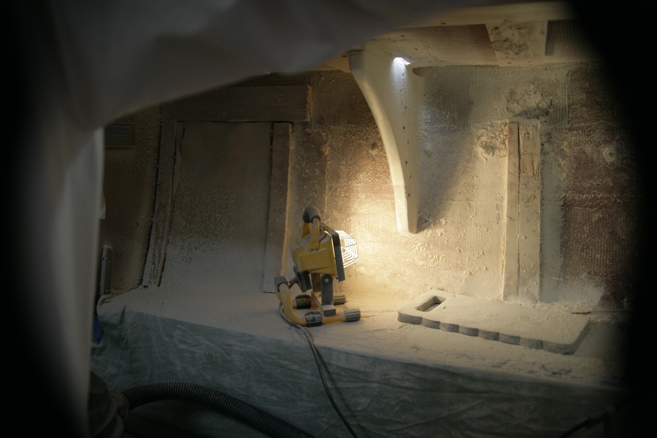
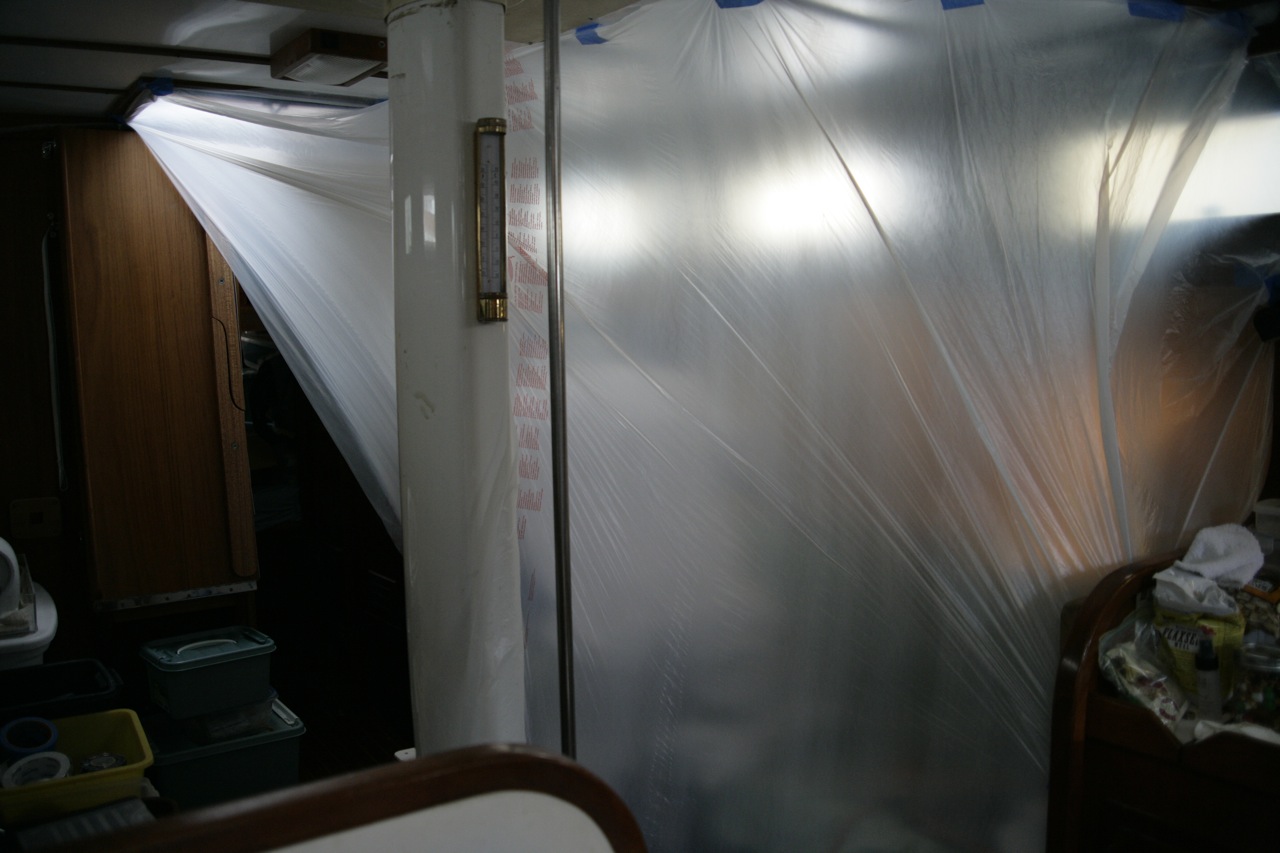
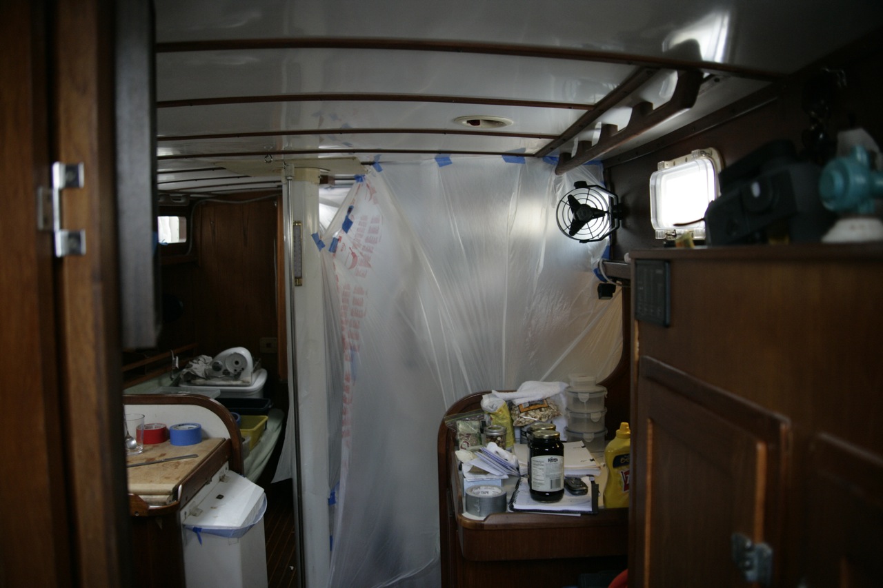
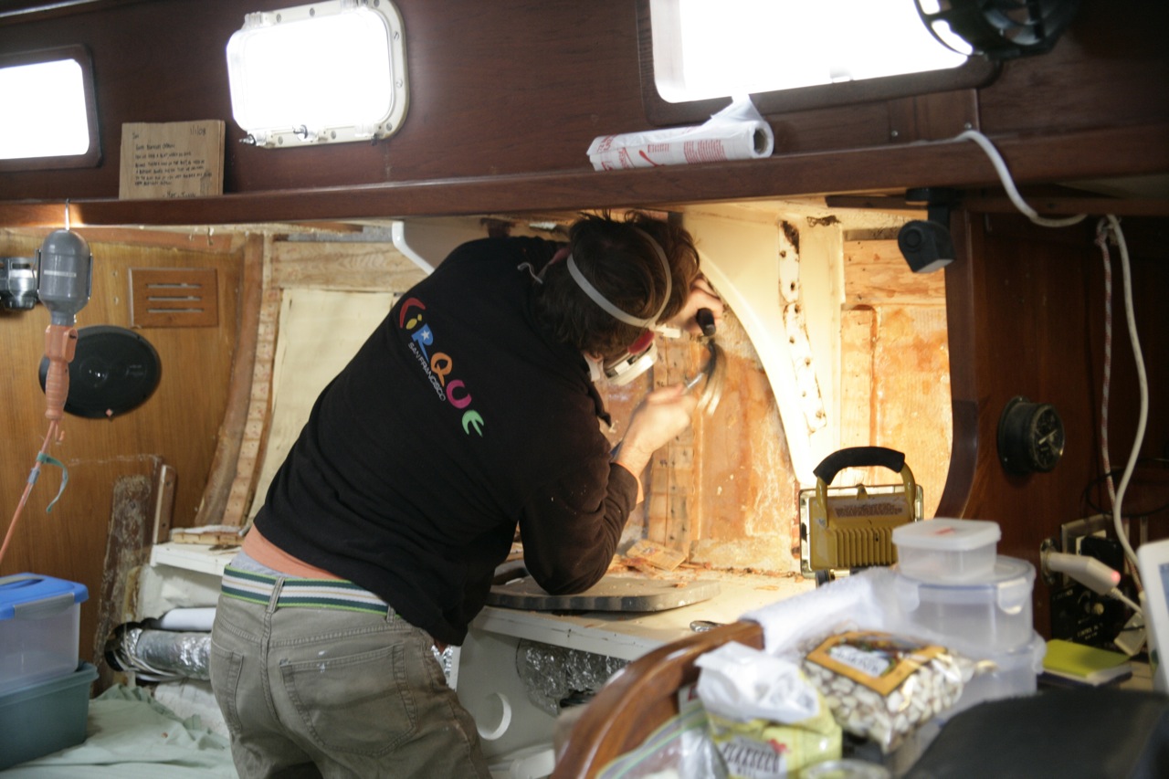
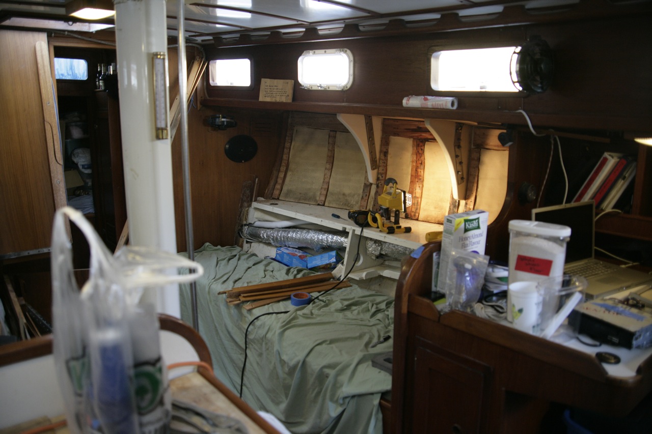
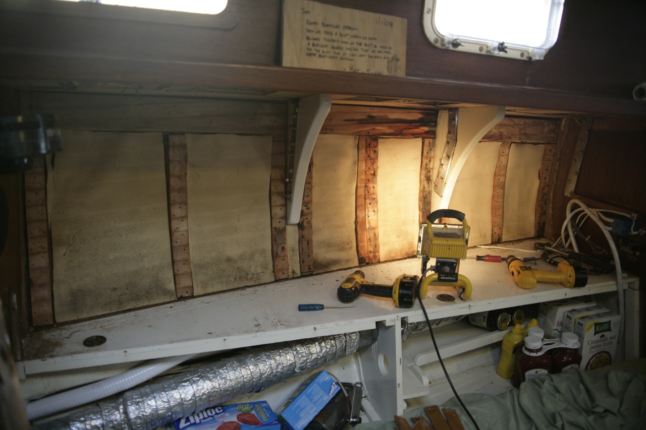
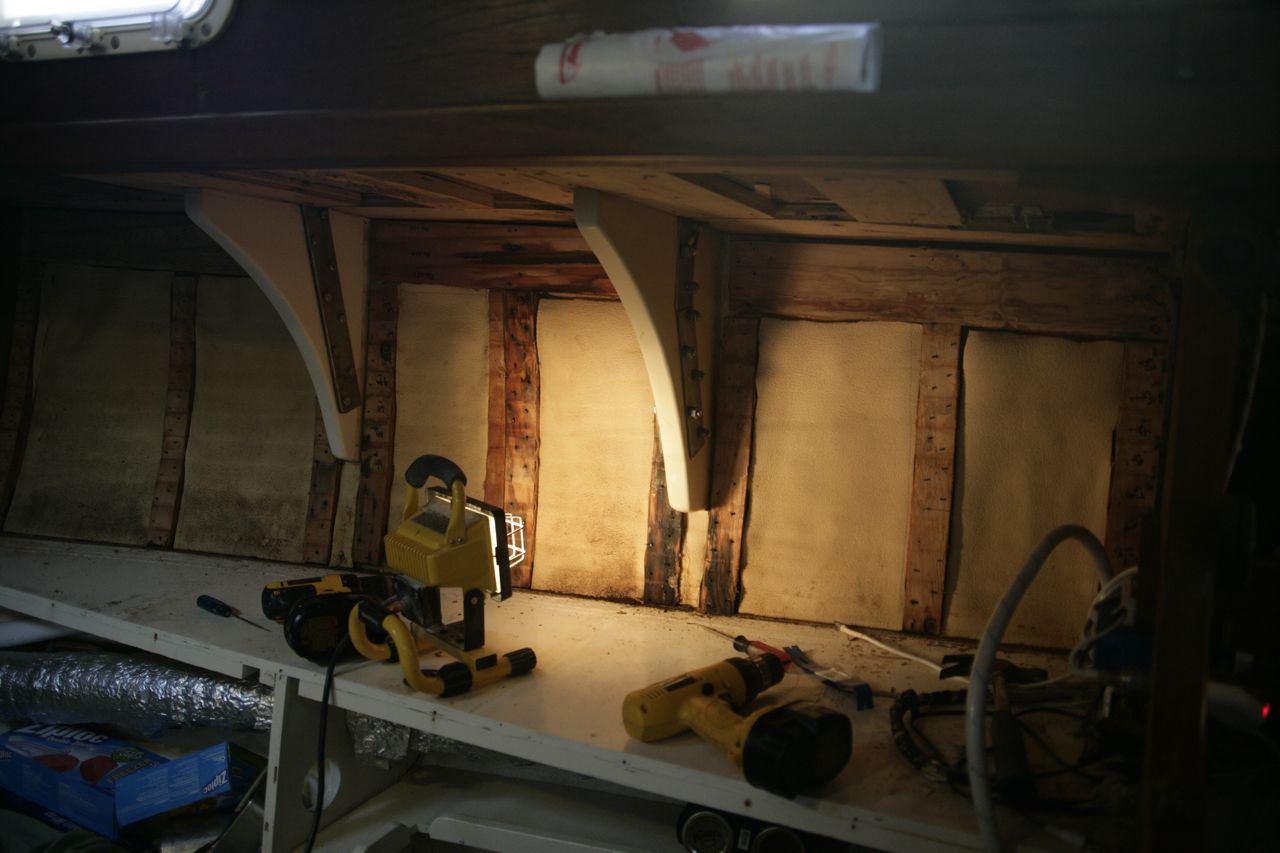
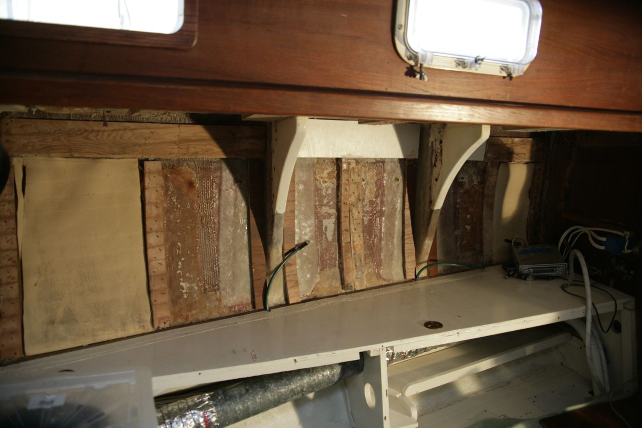
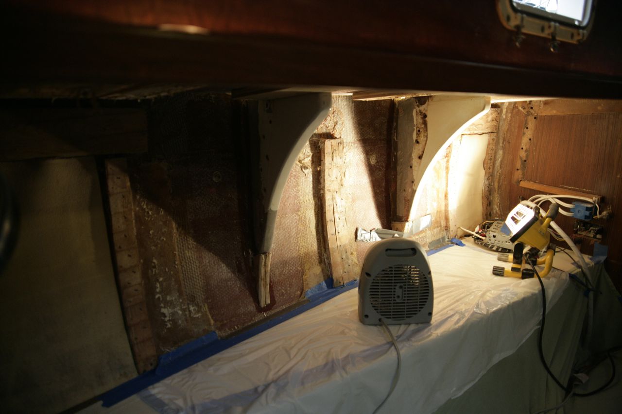
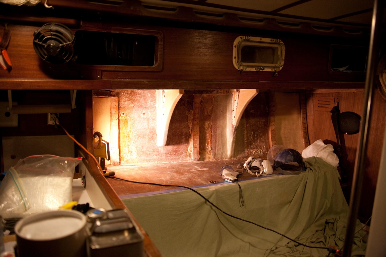
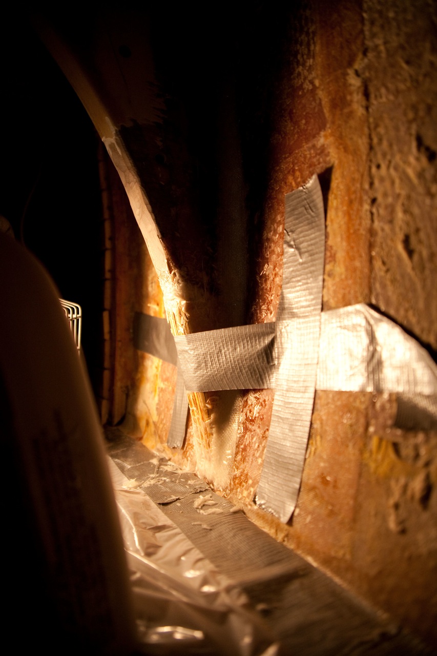
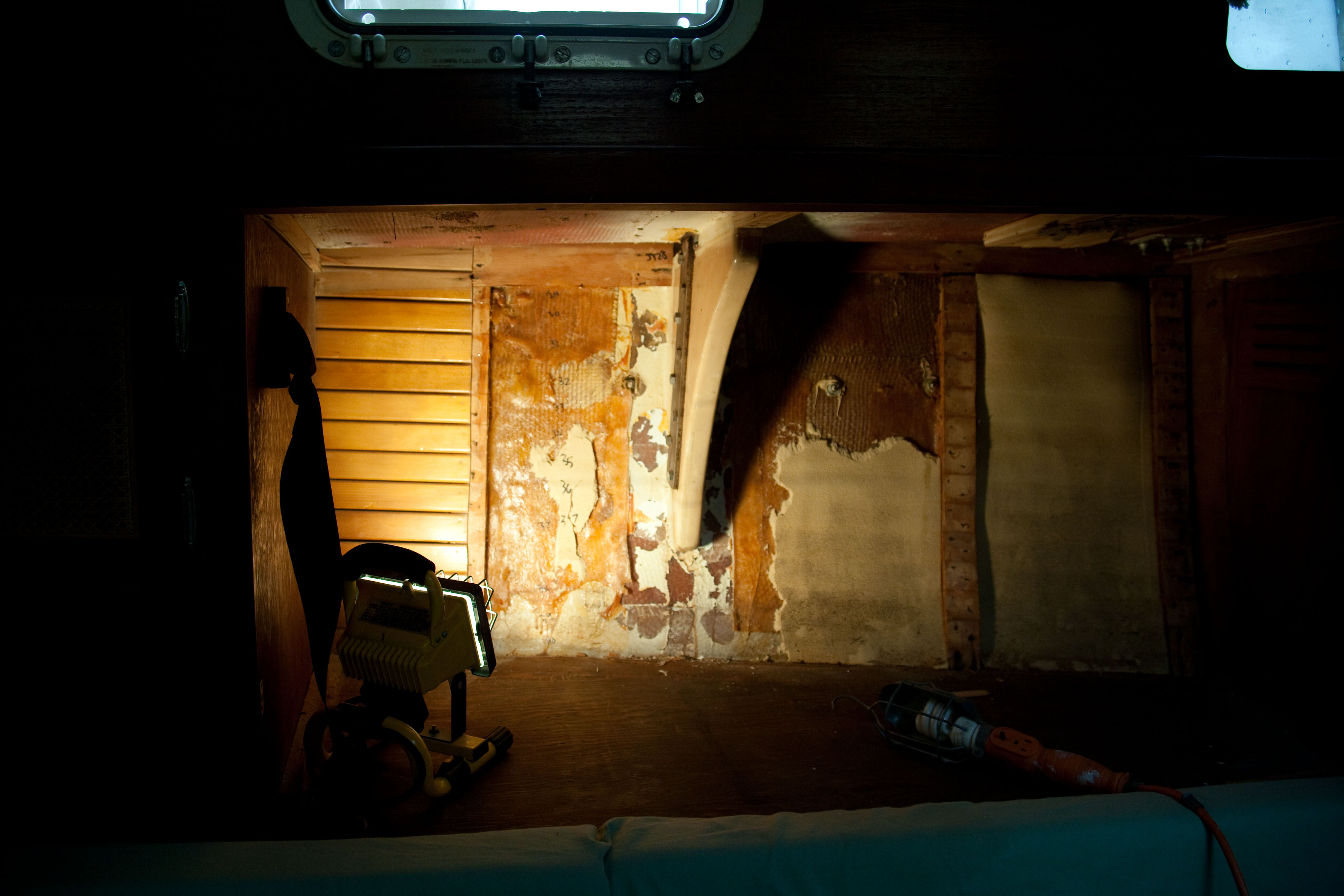
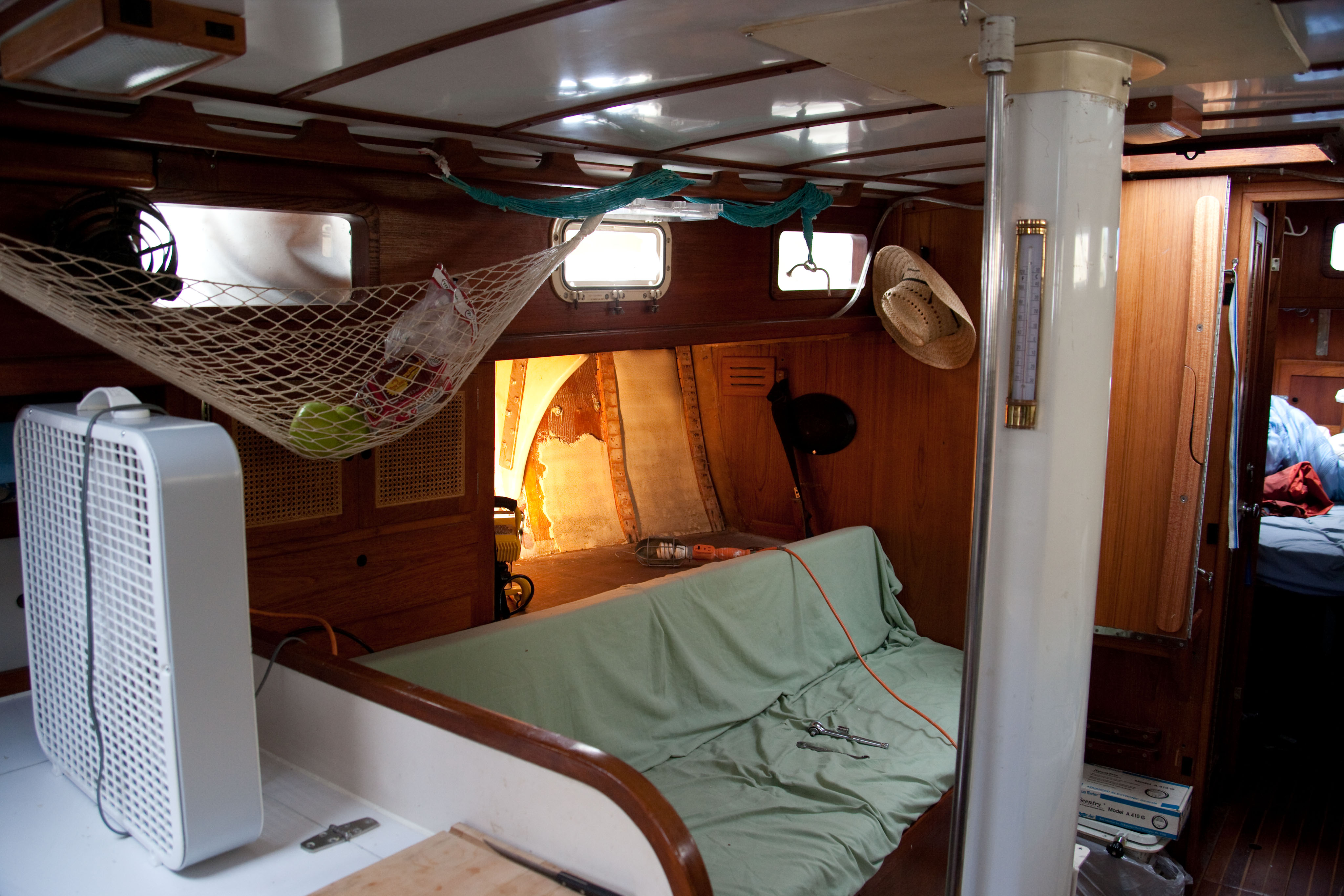
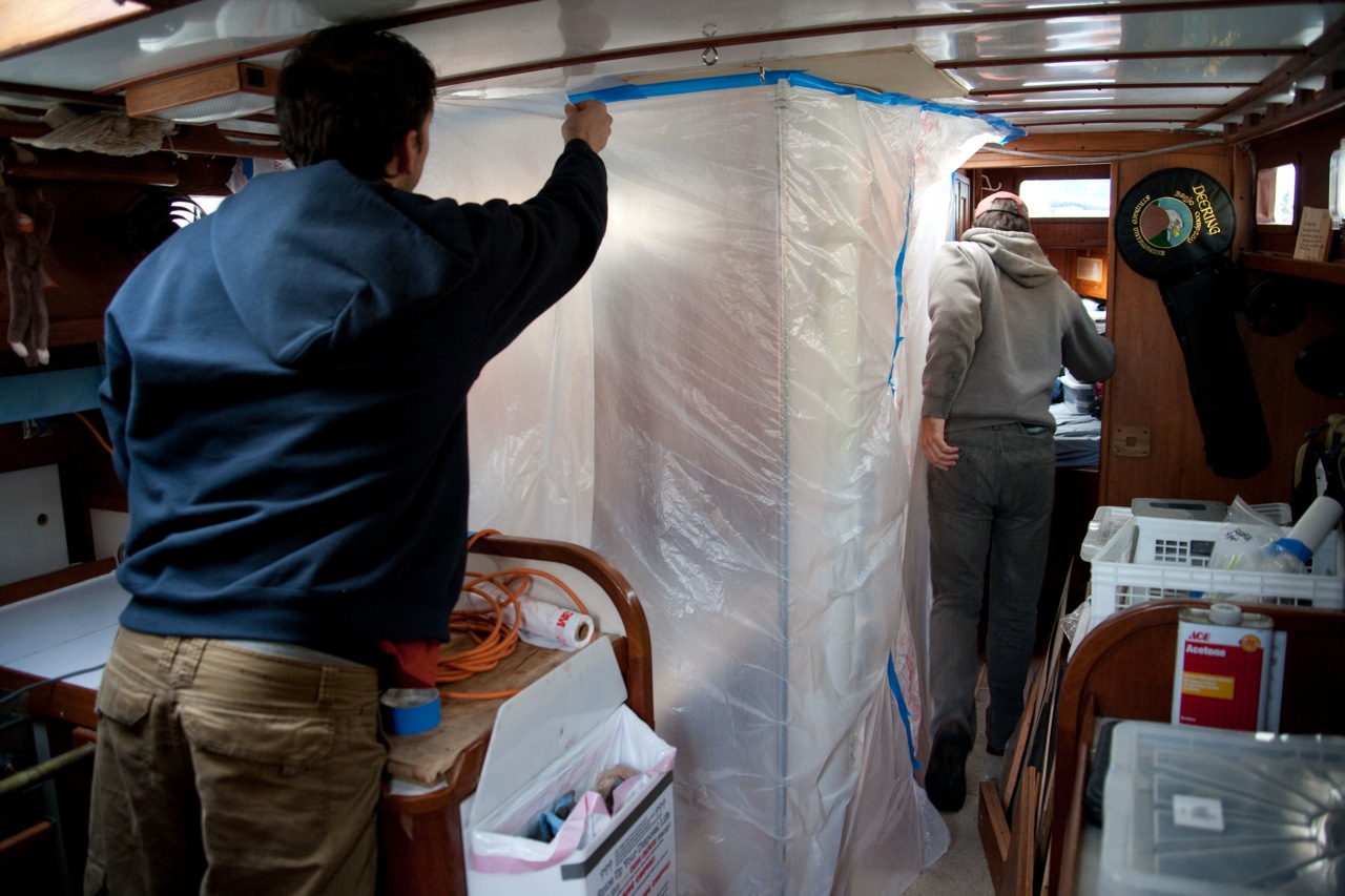
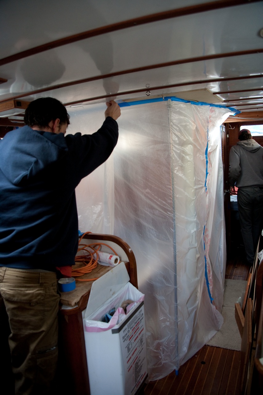
    This job was massive, and I didn’t have the luxury of time to sit back and consider.  I forged ahead, ripping out the cabinetry on both the port and starboard sides, then the slats, and then going to town with the grinder.  Making fiberglass snow a 1/2″ thick that covered everything–thank god I taped it all off with plastic.  Even with a box fan in the hatch sucking it out, it was still insanely uncomfortable.

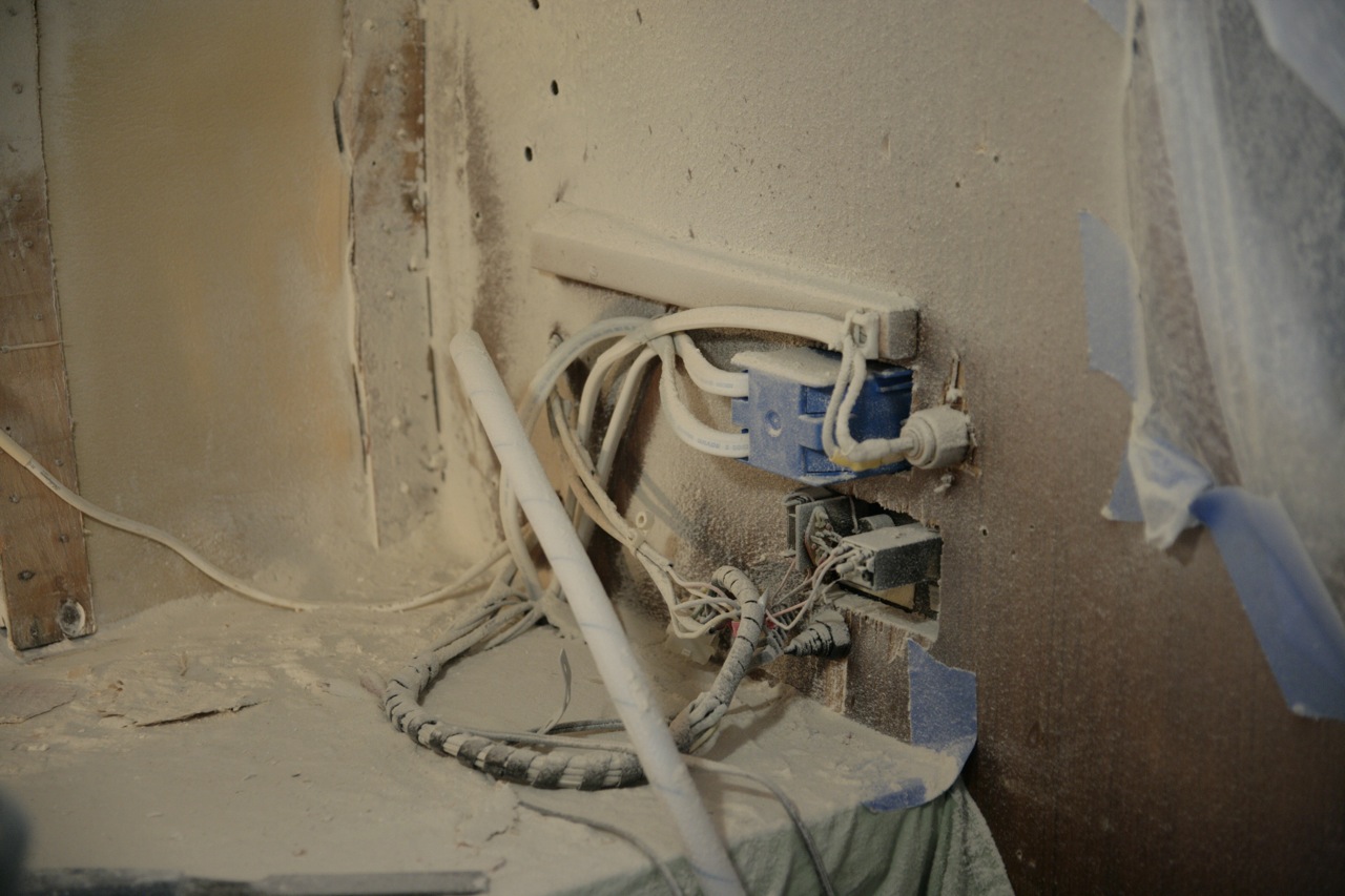
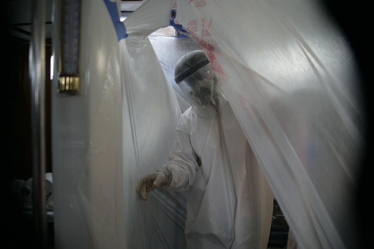
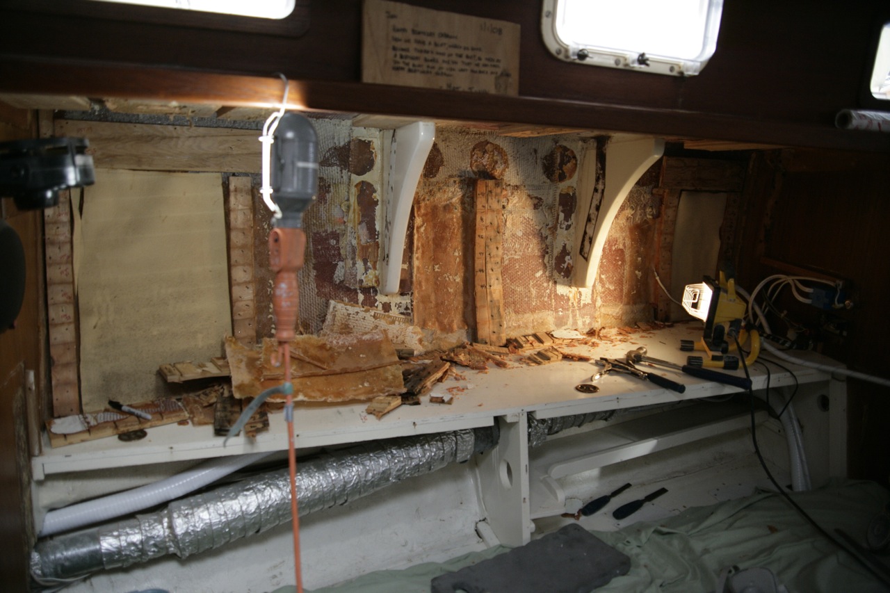
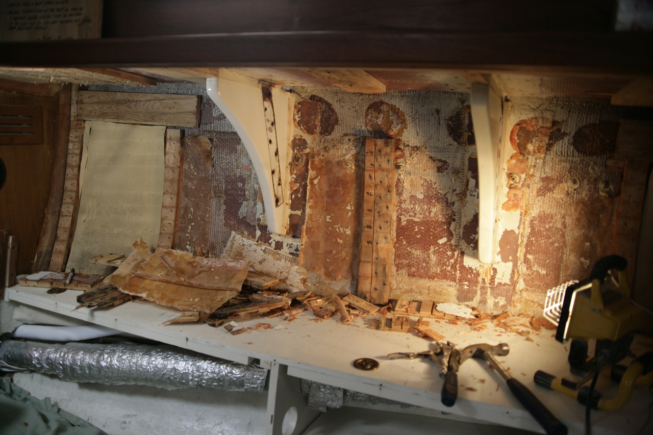
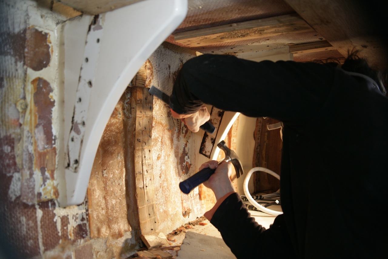
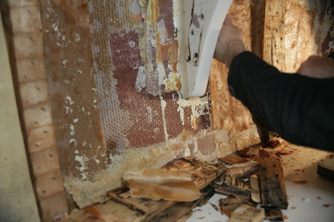
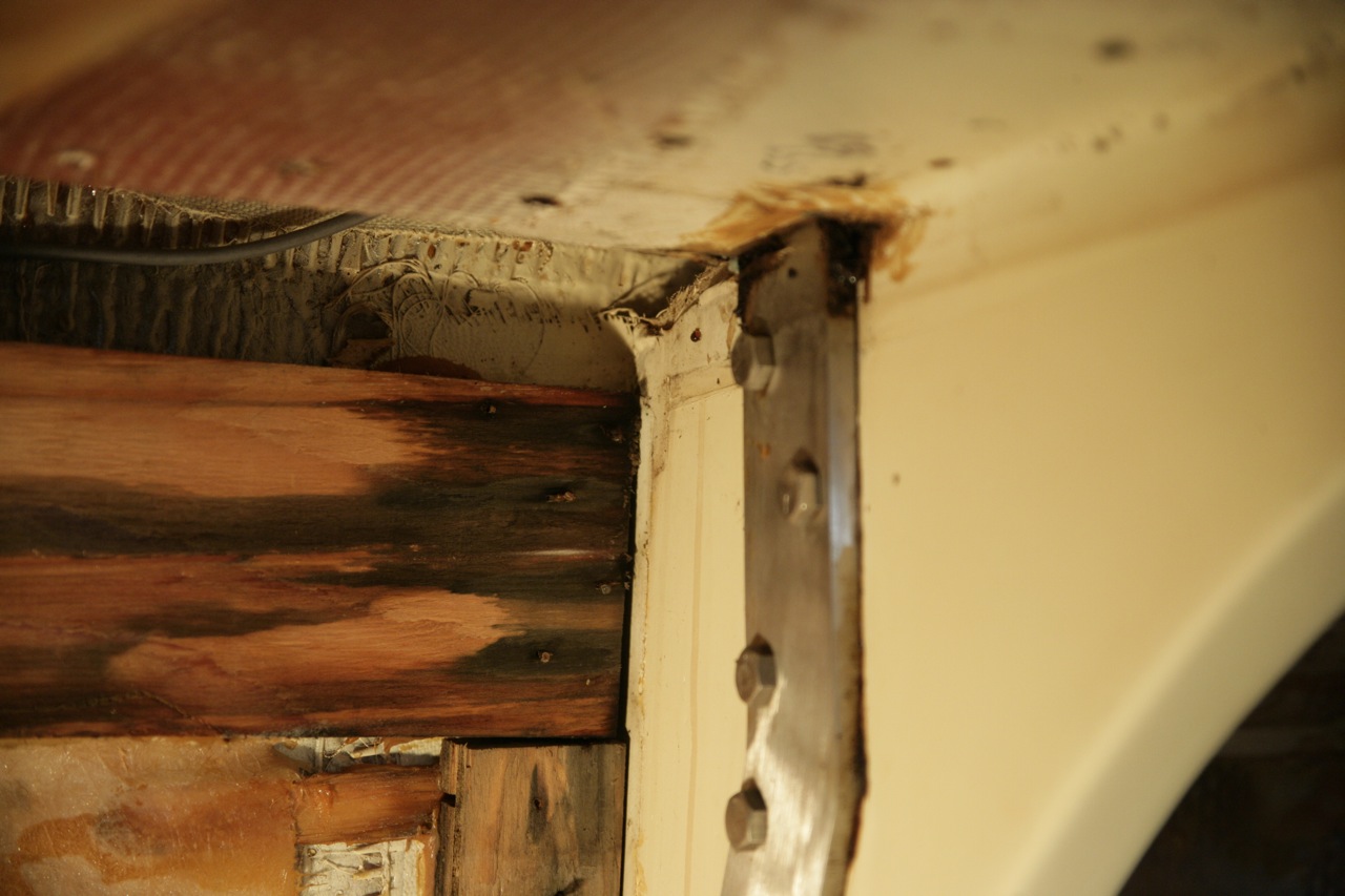
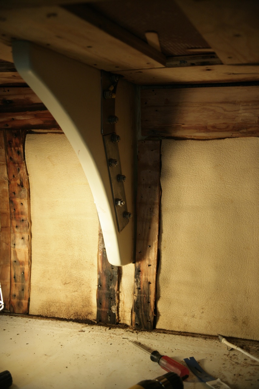
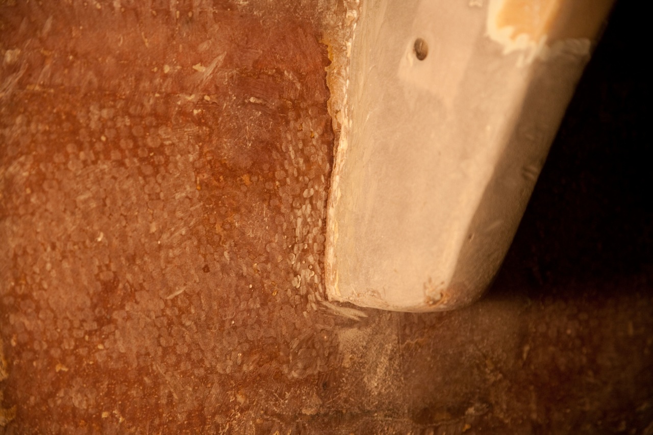
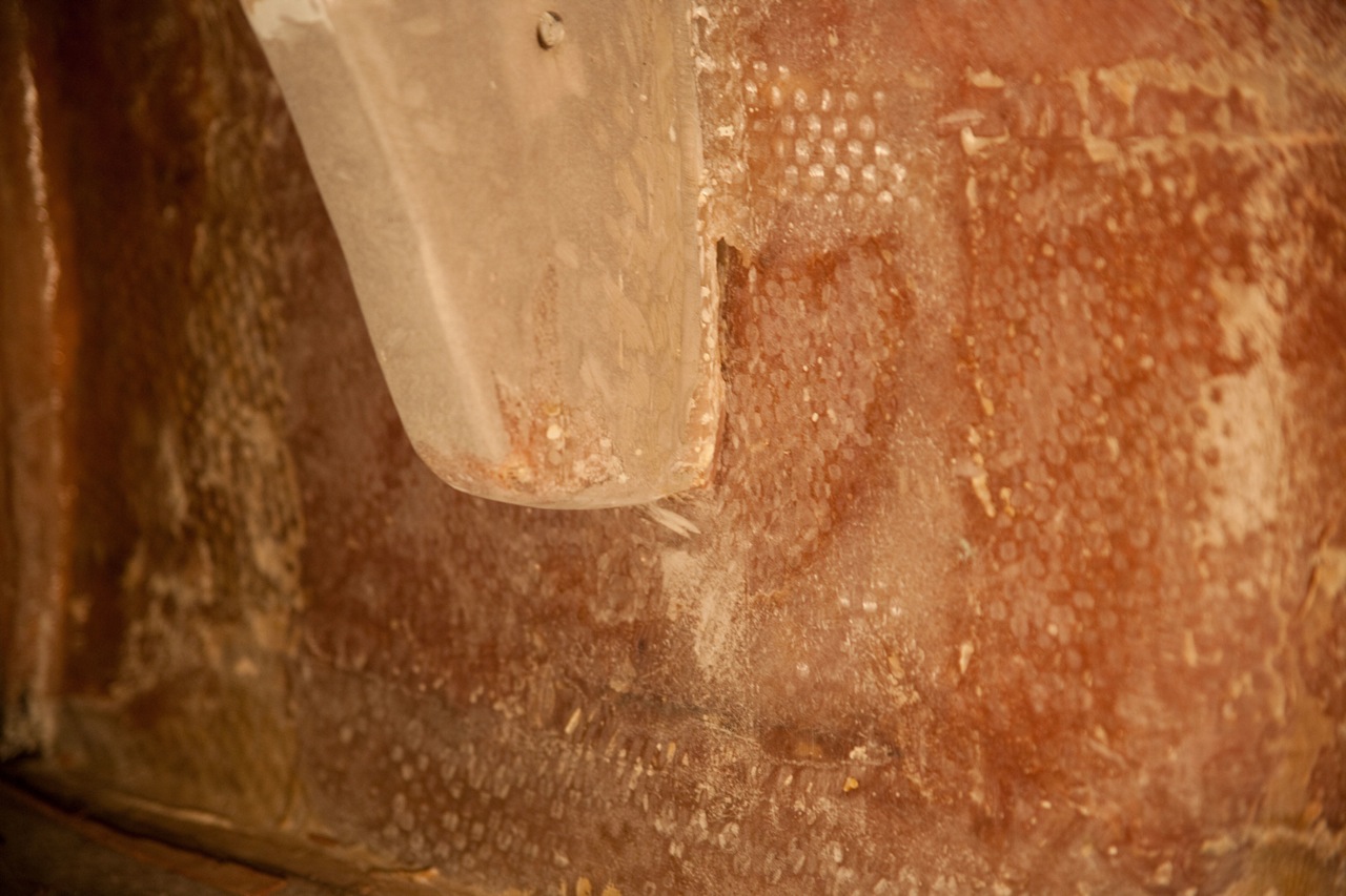
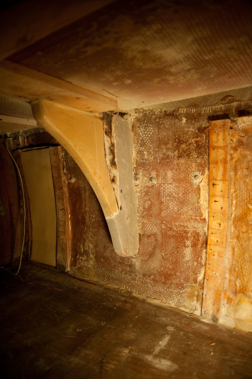
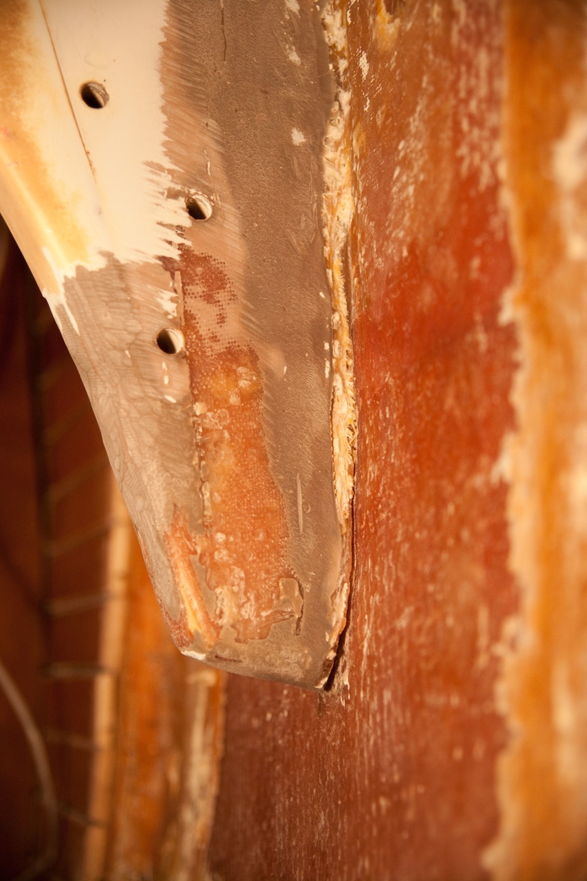
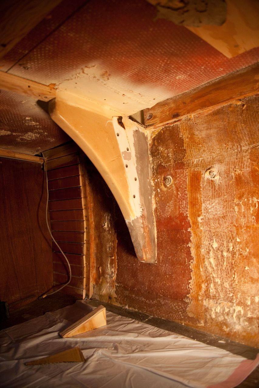
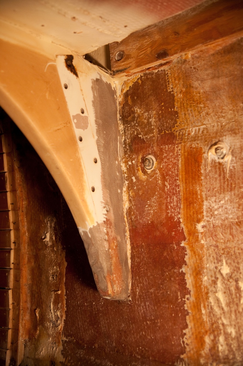
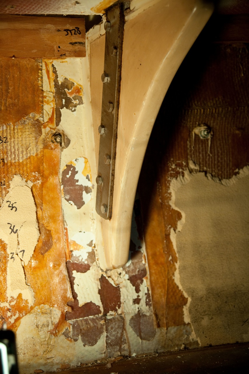
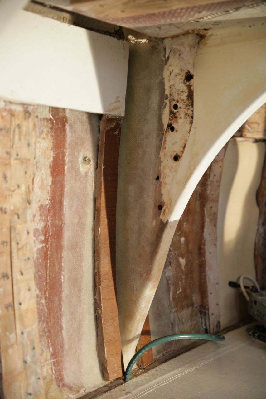
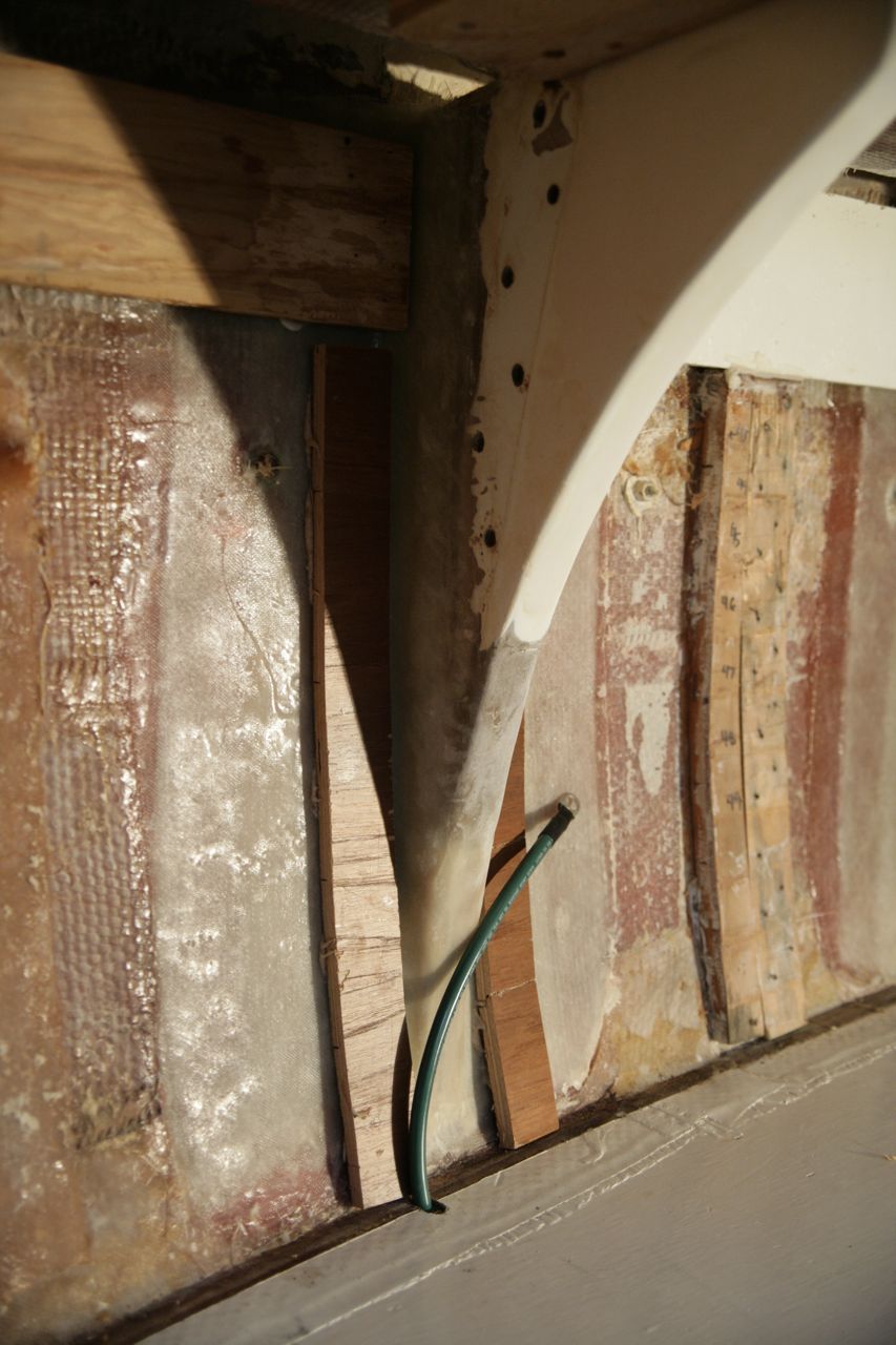
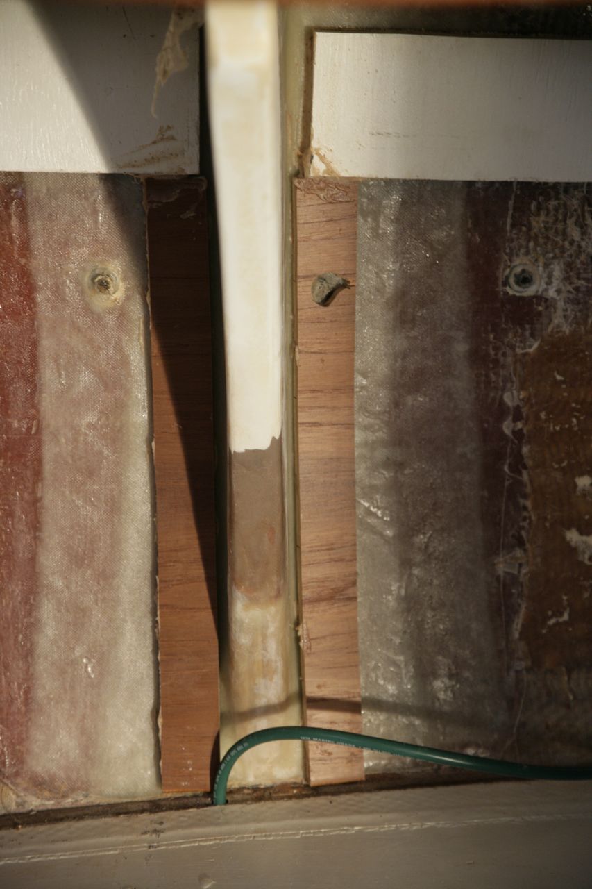
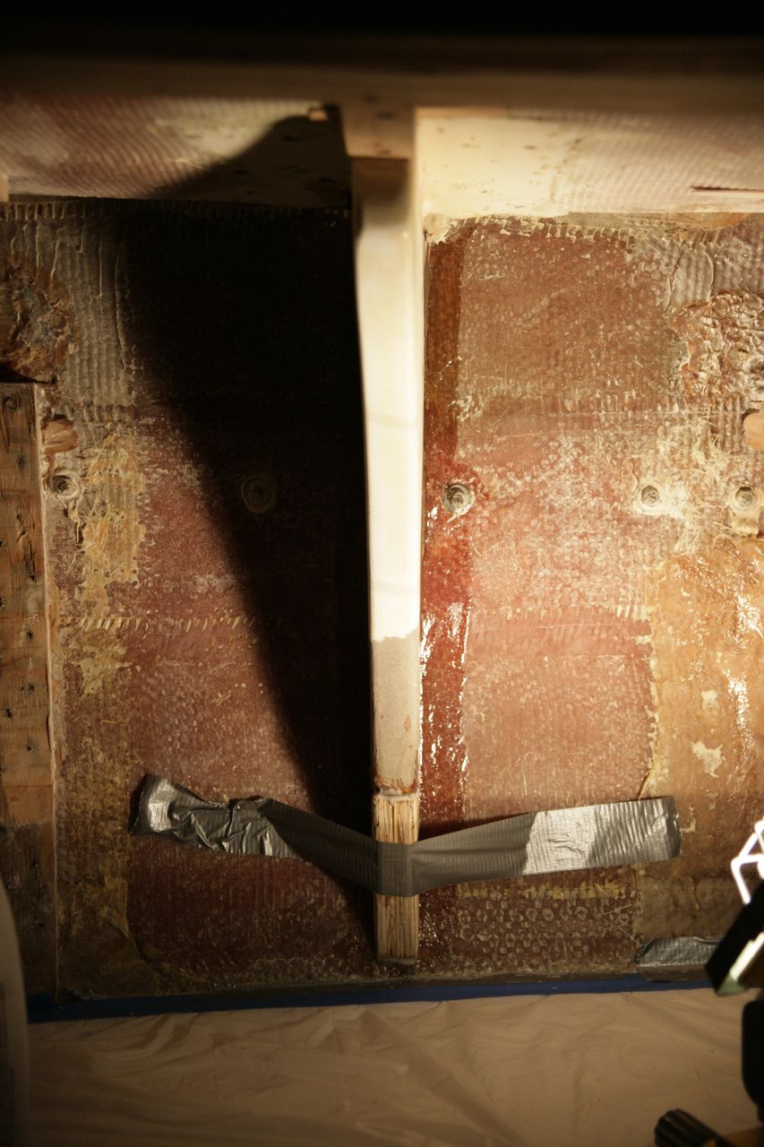
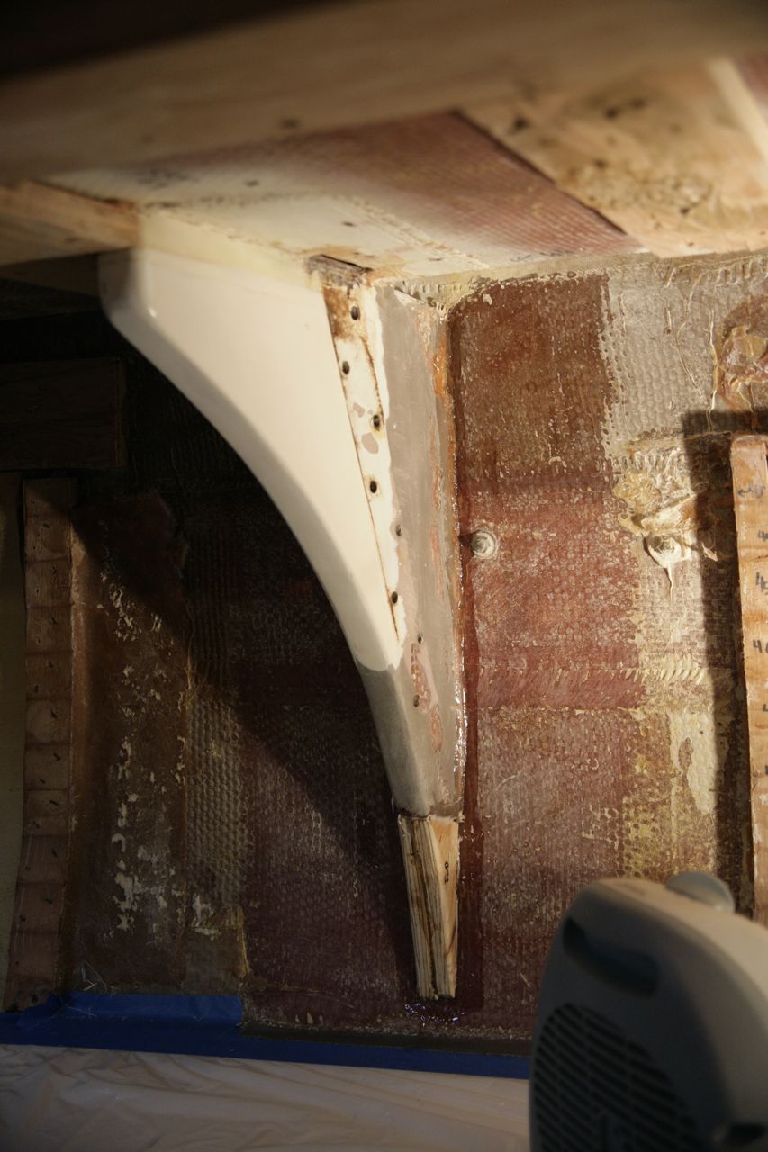
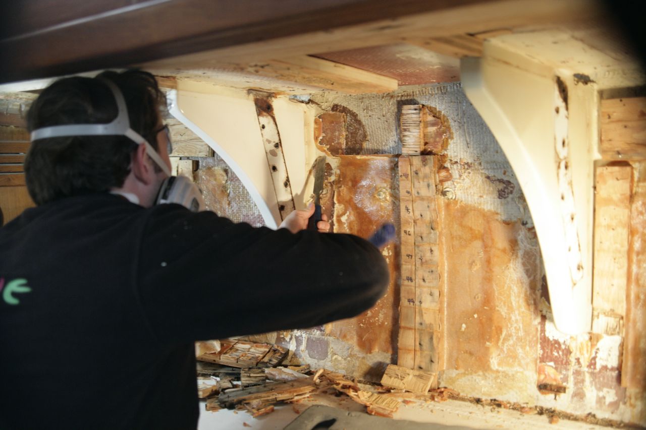
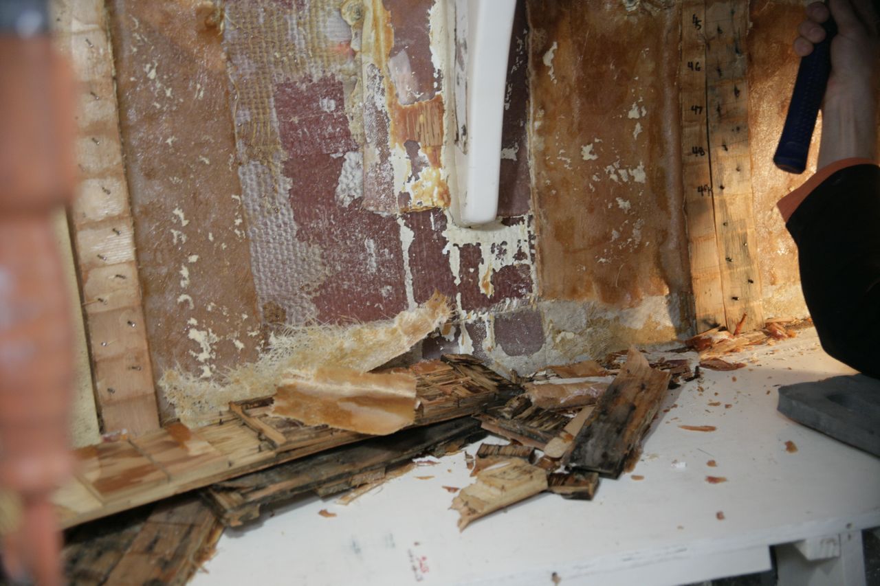
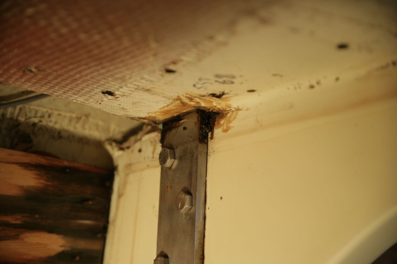
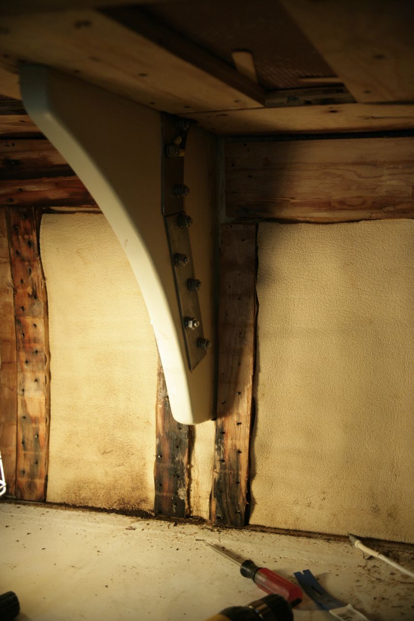
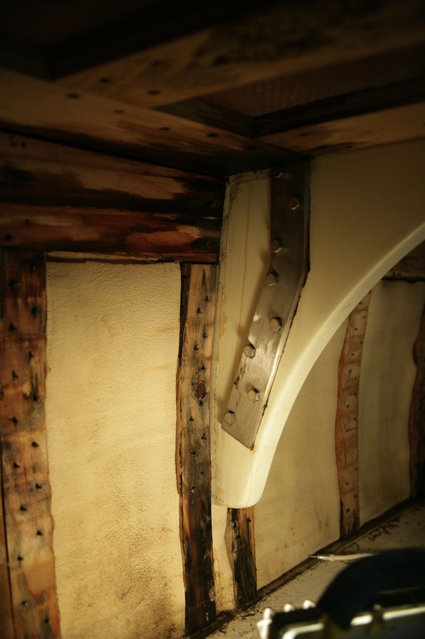
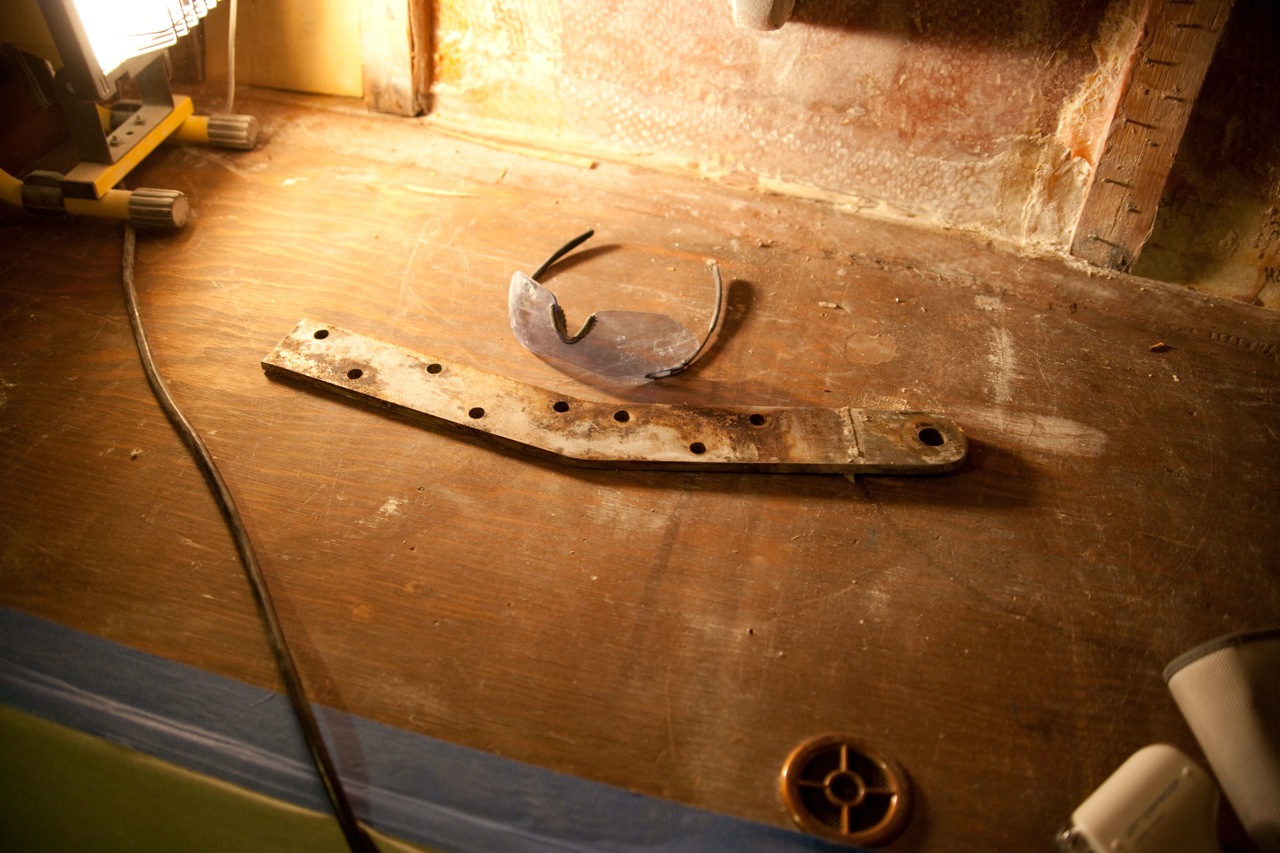
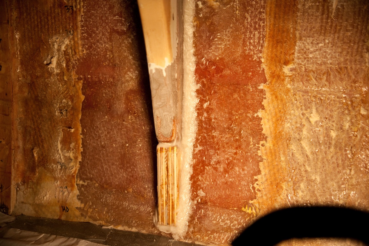
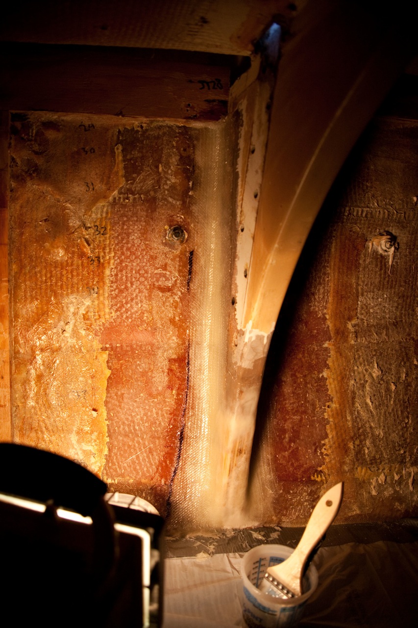
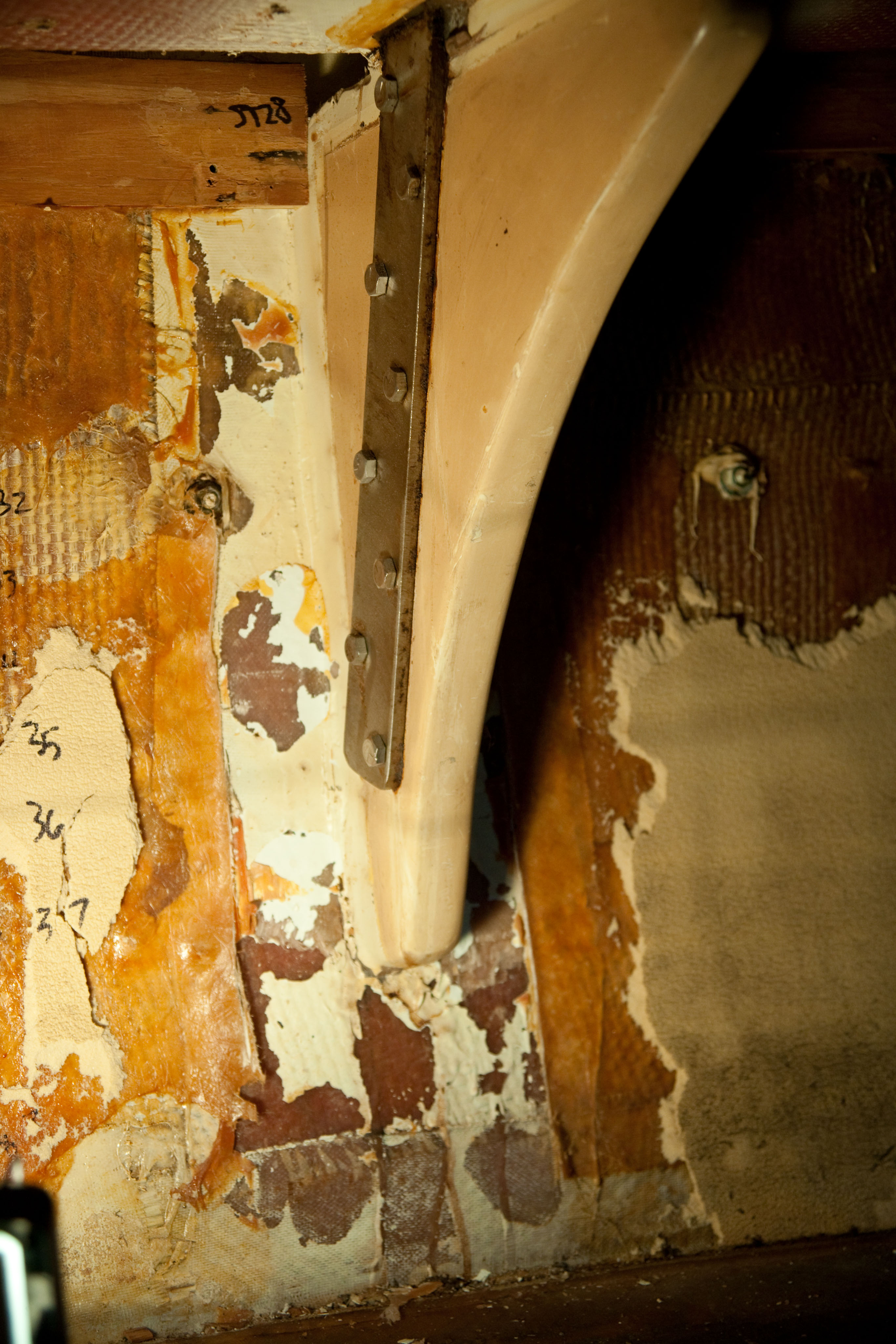
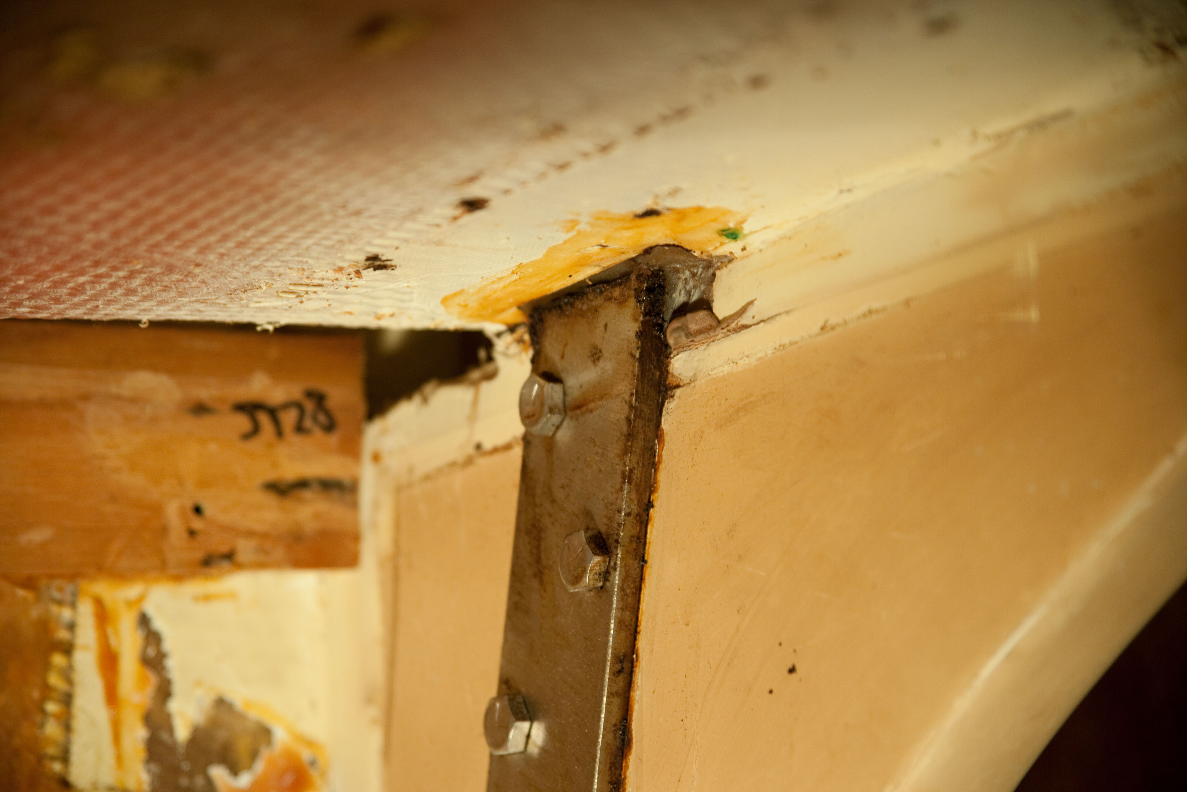
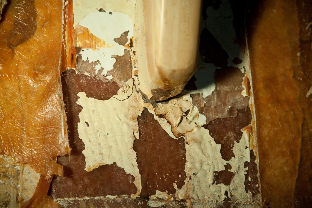
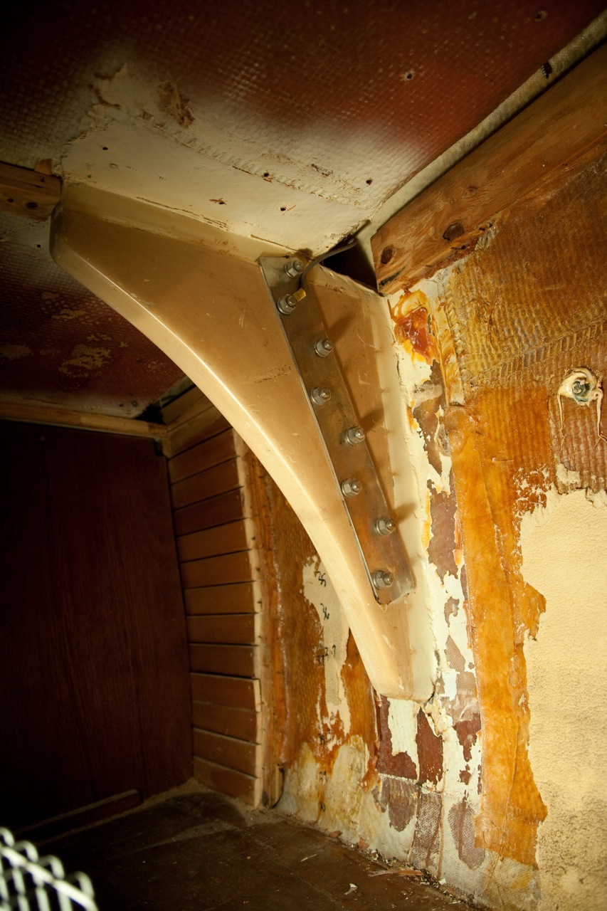
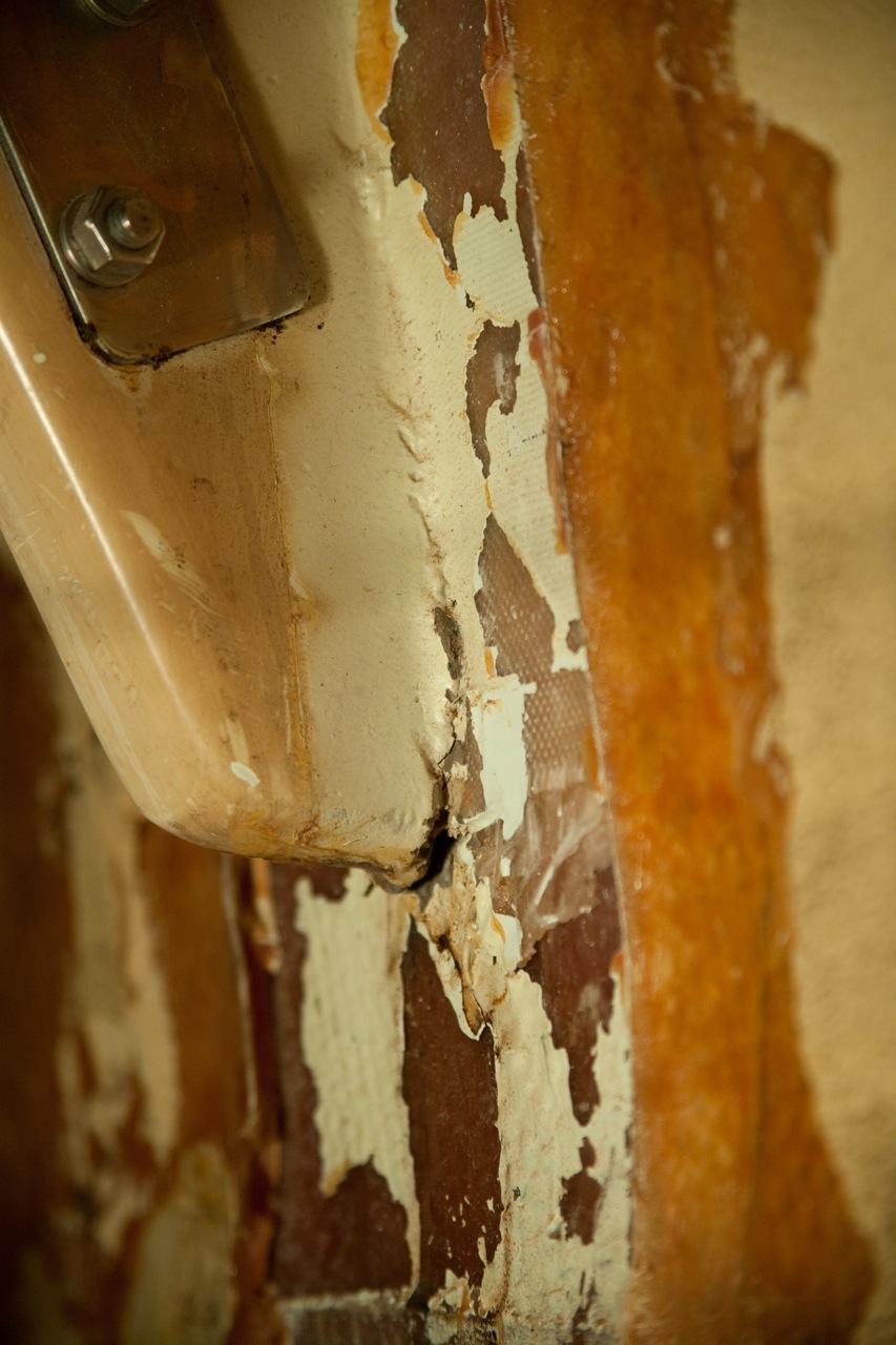
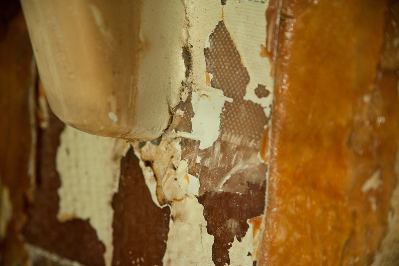
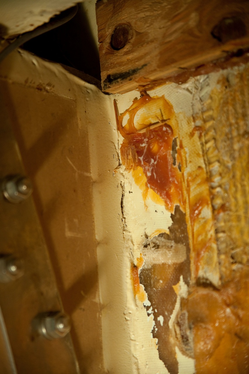
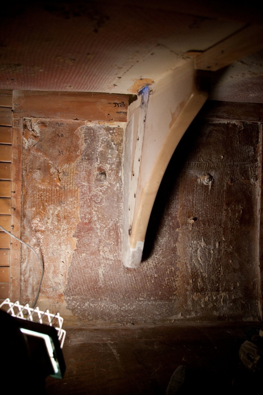
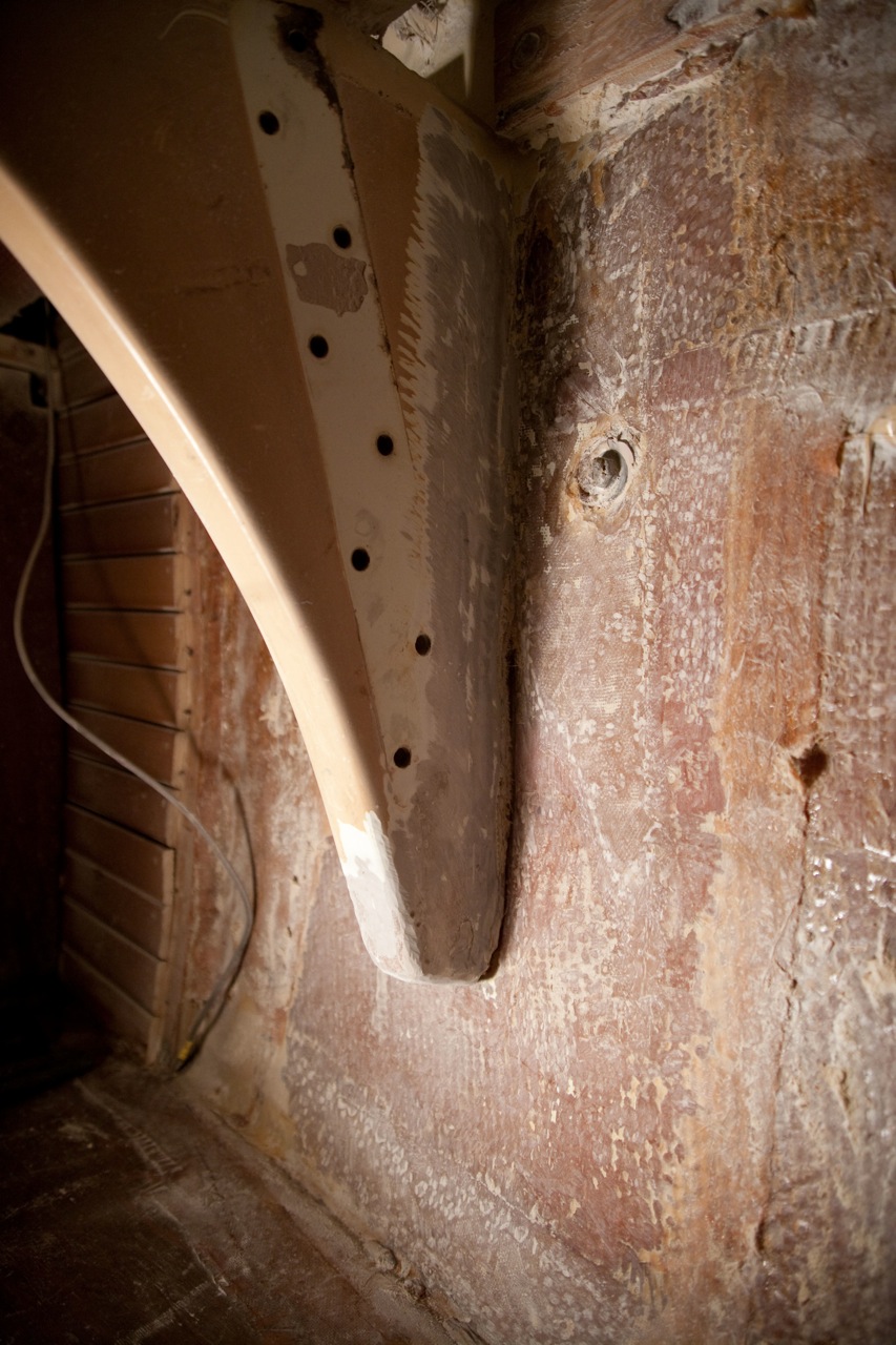
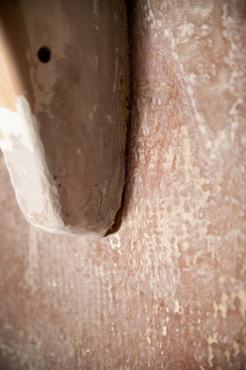
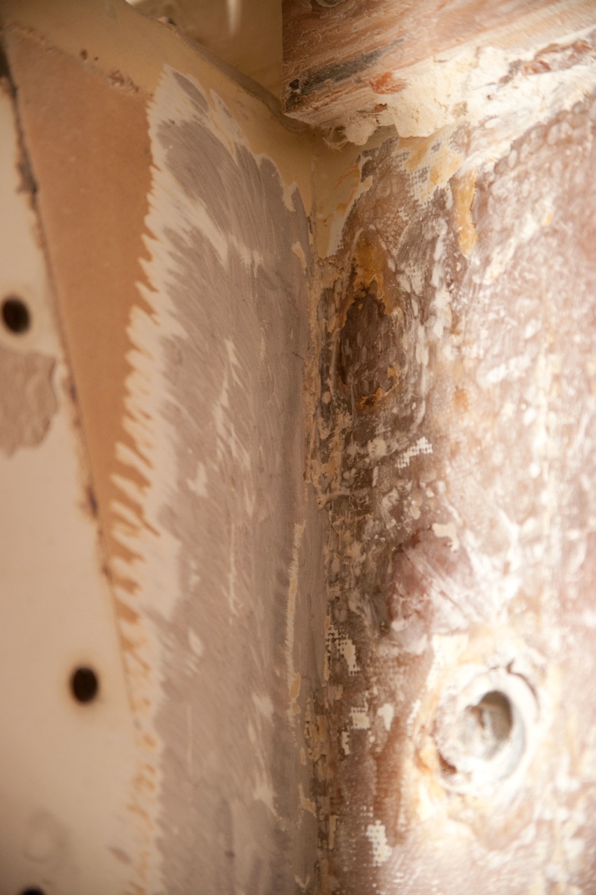
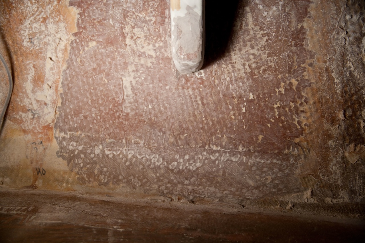
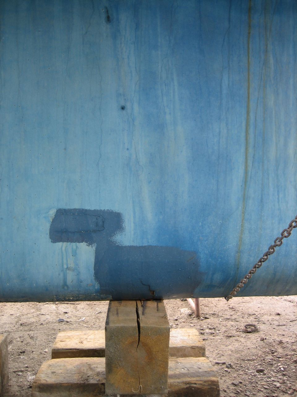
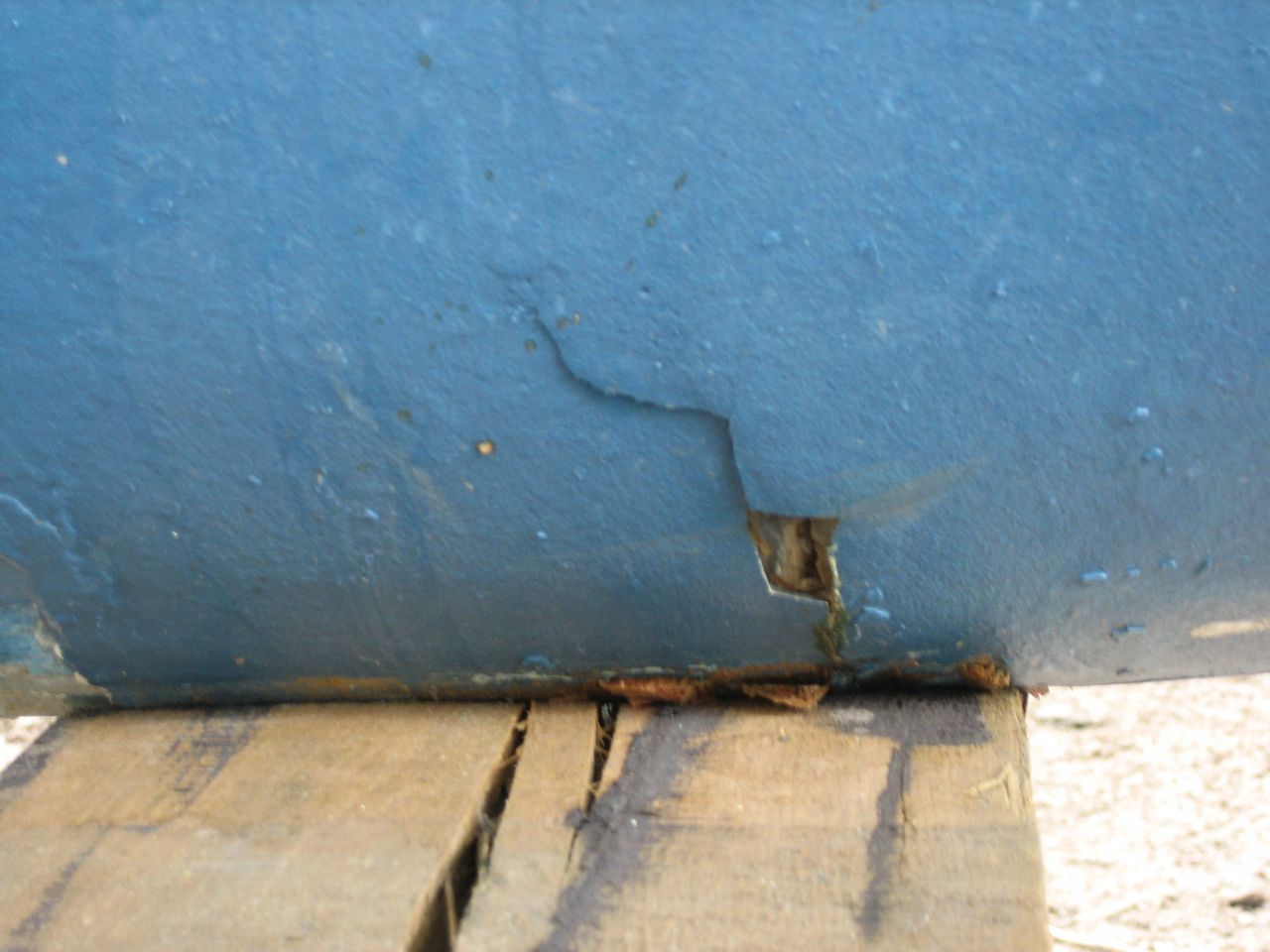
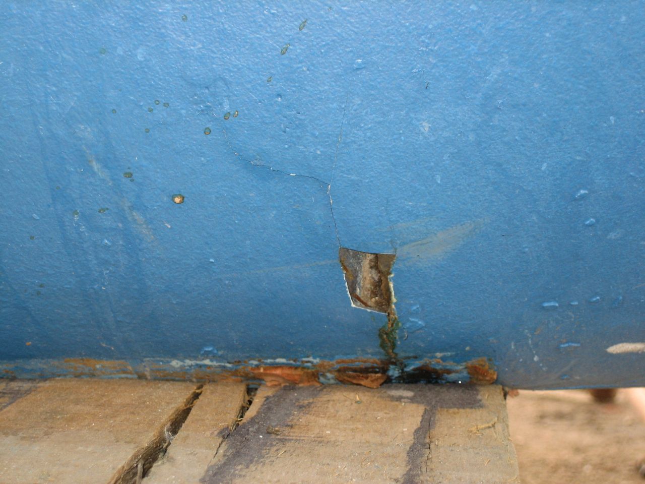
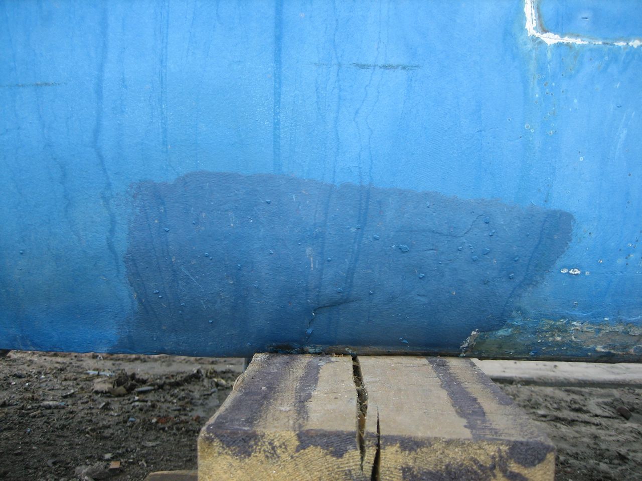
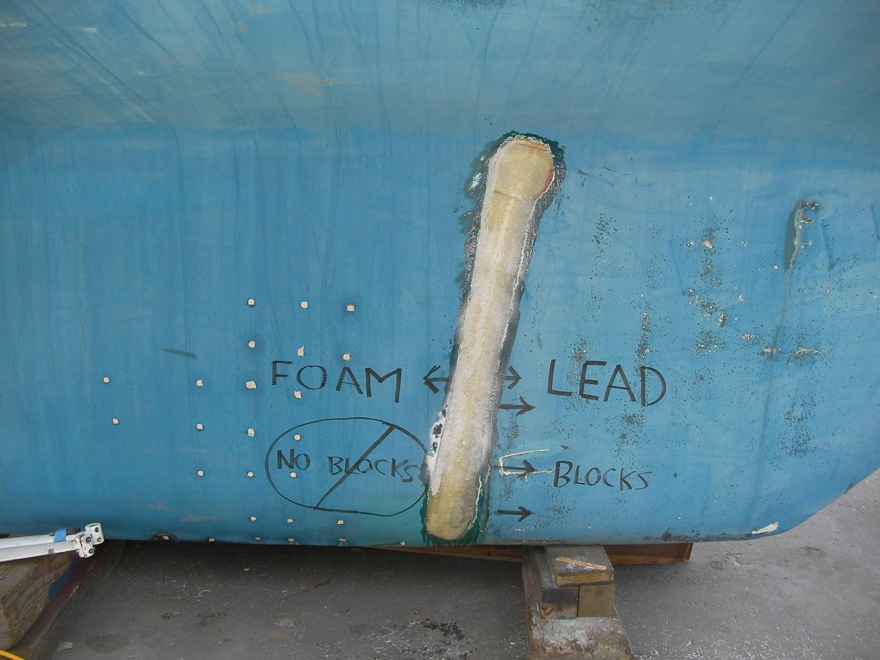
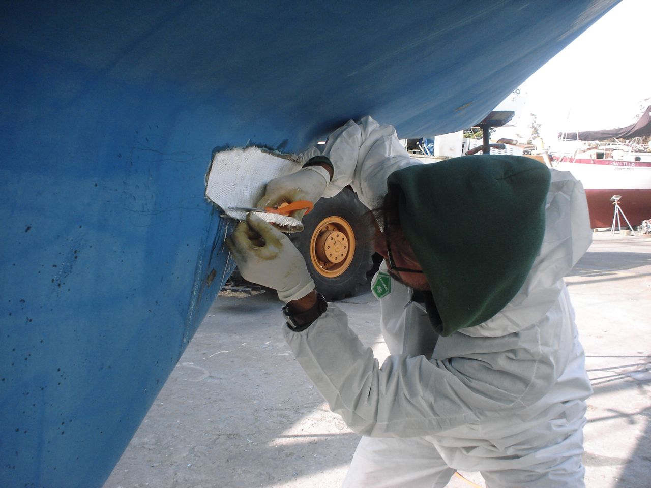
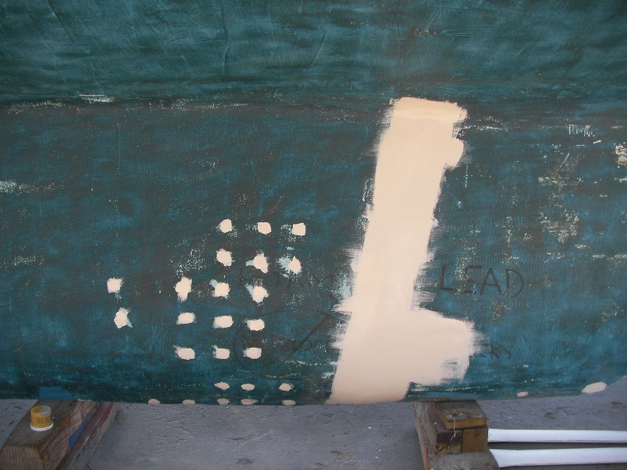
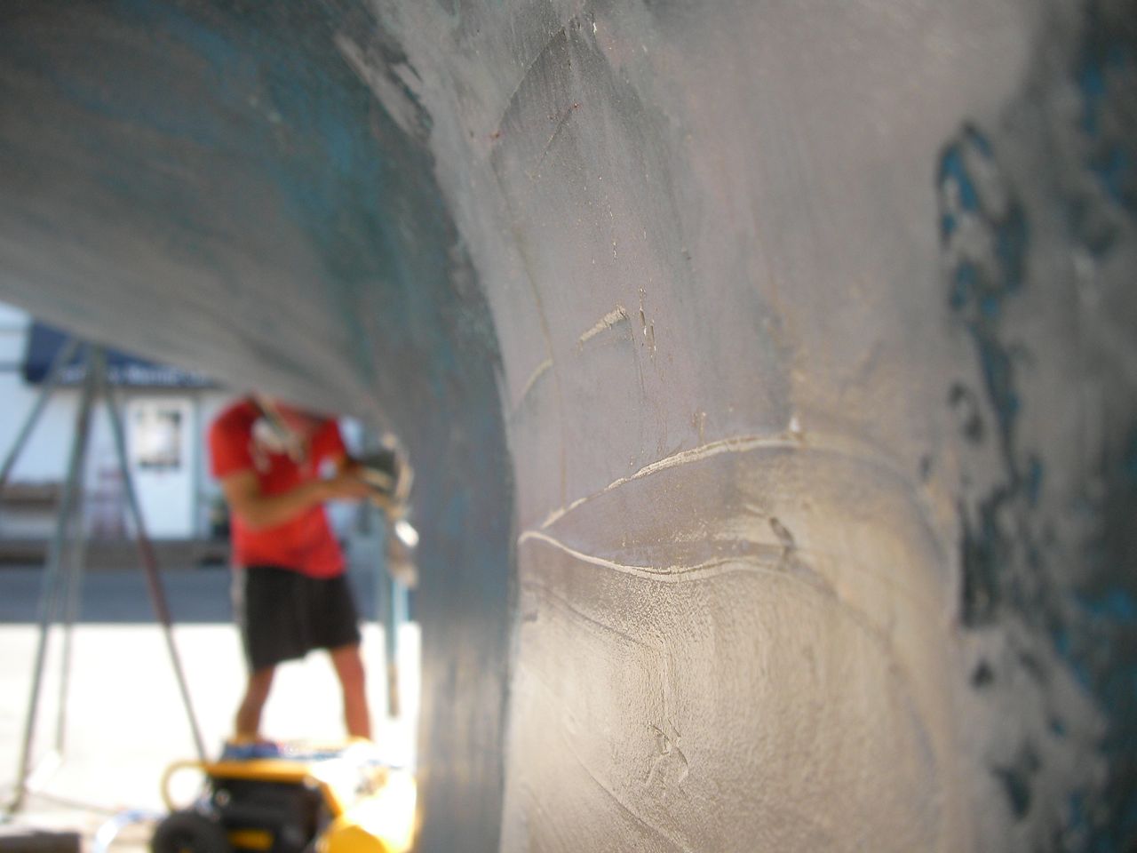
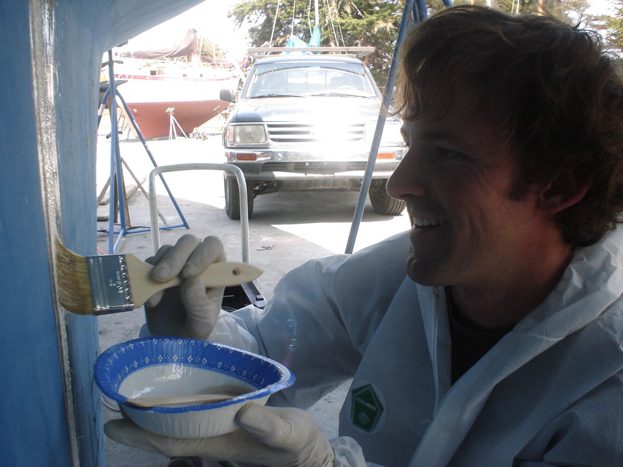
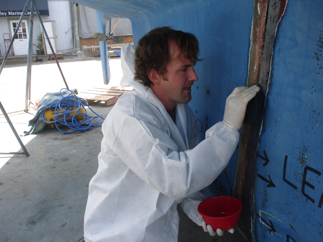
    On the starboard side the cabinet didn’t come out so easily: I ended up breaking it a little in the process.  On immediate inspection, both of these knees showed a small gap and cracking between the bottom point and the hull, indicating that they had indeed parted from the hull somewhat.  After chiseling off the old kerfs (those vertical pieces of wood on either side of the knees, to which the horizontal trim battens were nailed) I was able to see that they used entirely too little tabbing to secure the knee to the hull.  In the process of grinding off the old, bad stuff, I discovered that at the lowest level the tabbing had delaminated from the hull along its entire length, so I ended up having to grind off all of the old tabbing from the hull (I wasn’t that bad on the port side).  I was in the bunny suit with the respirator and ear plugs and safety glasses and full face shield over that for 6 straight hours grinding away–it was a very unpleasant day.  By the time I was done I had created a 1/4″ of fiberglass “snow” over every single surface inside my bubble (as karen called it).

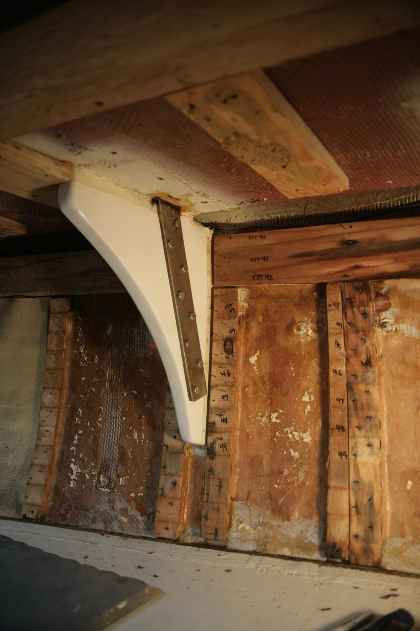
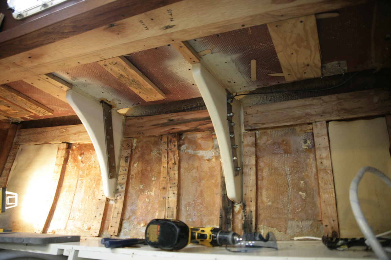
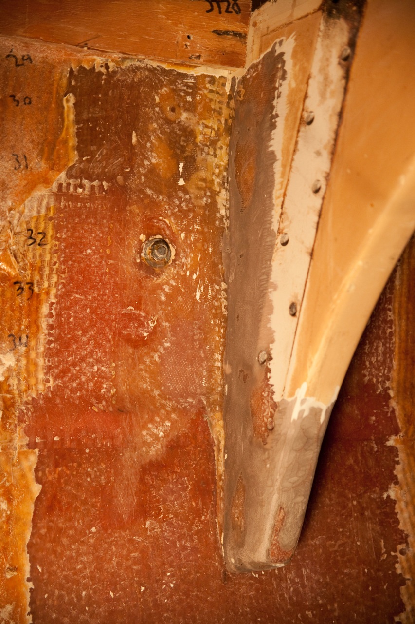
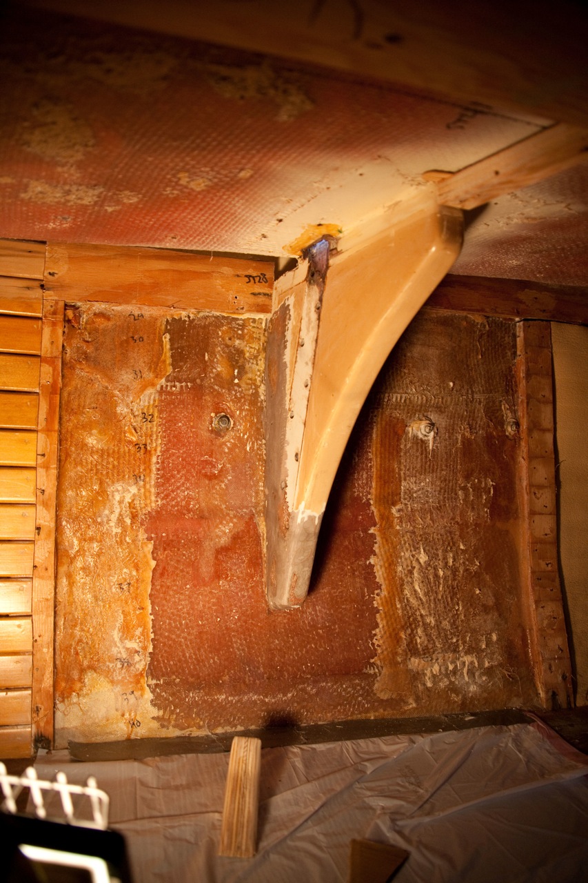
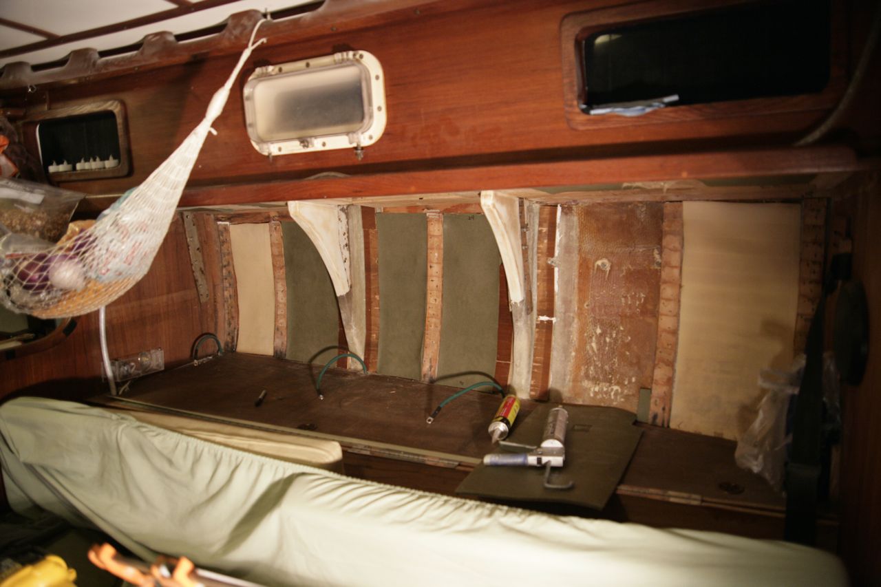
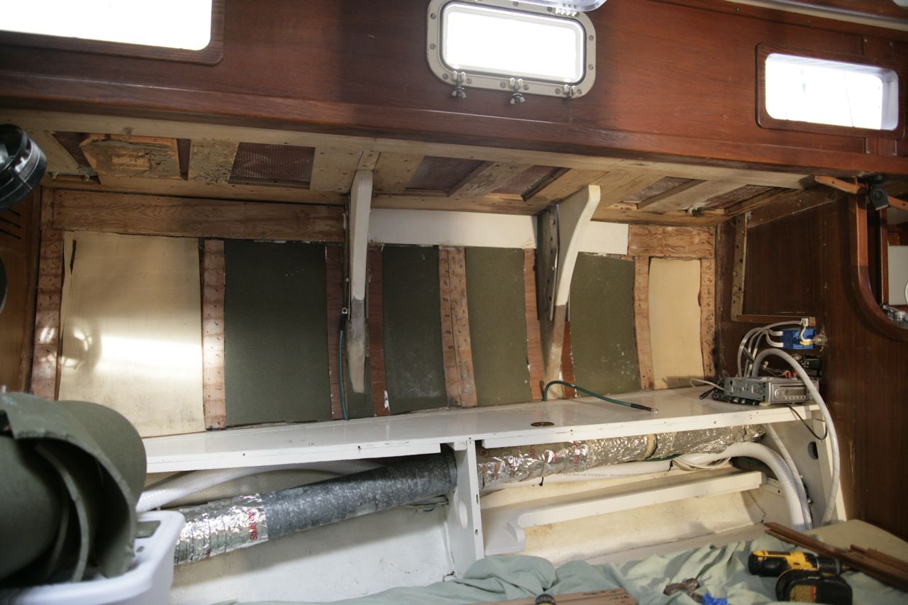
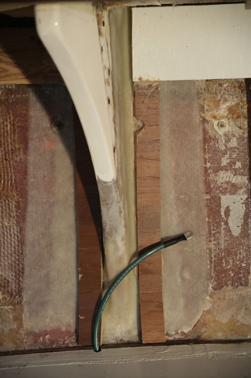
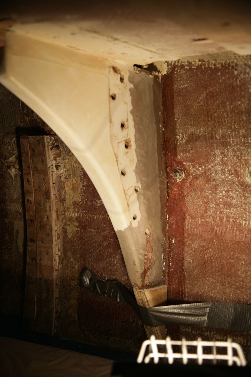
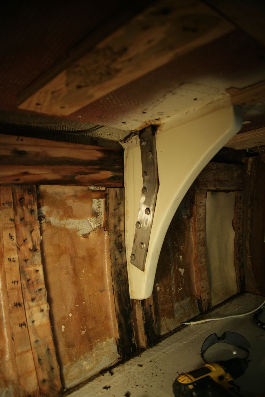
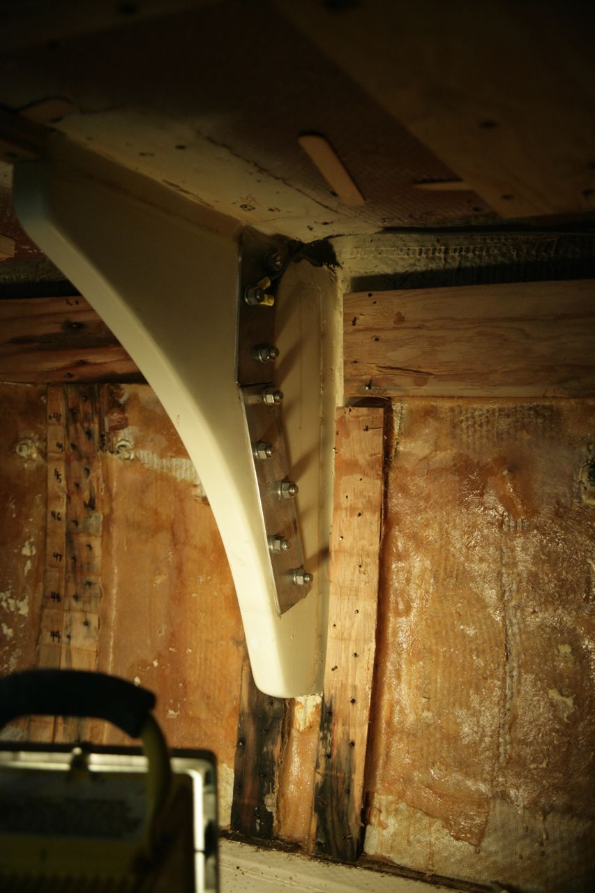
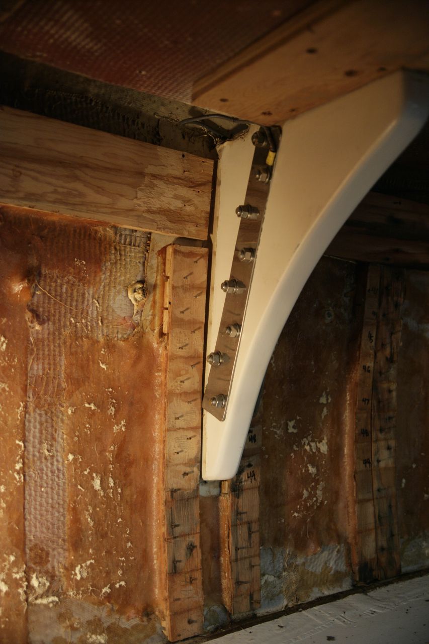
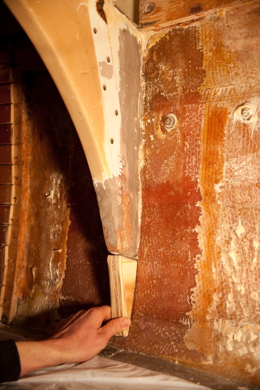
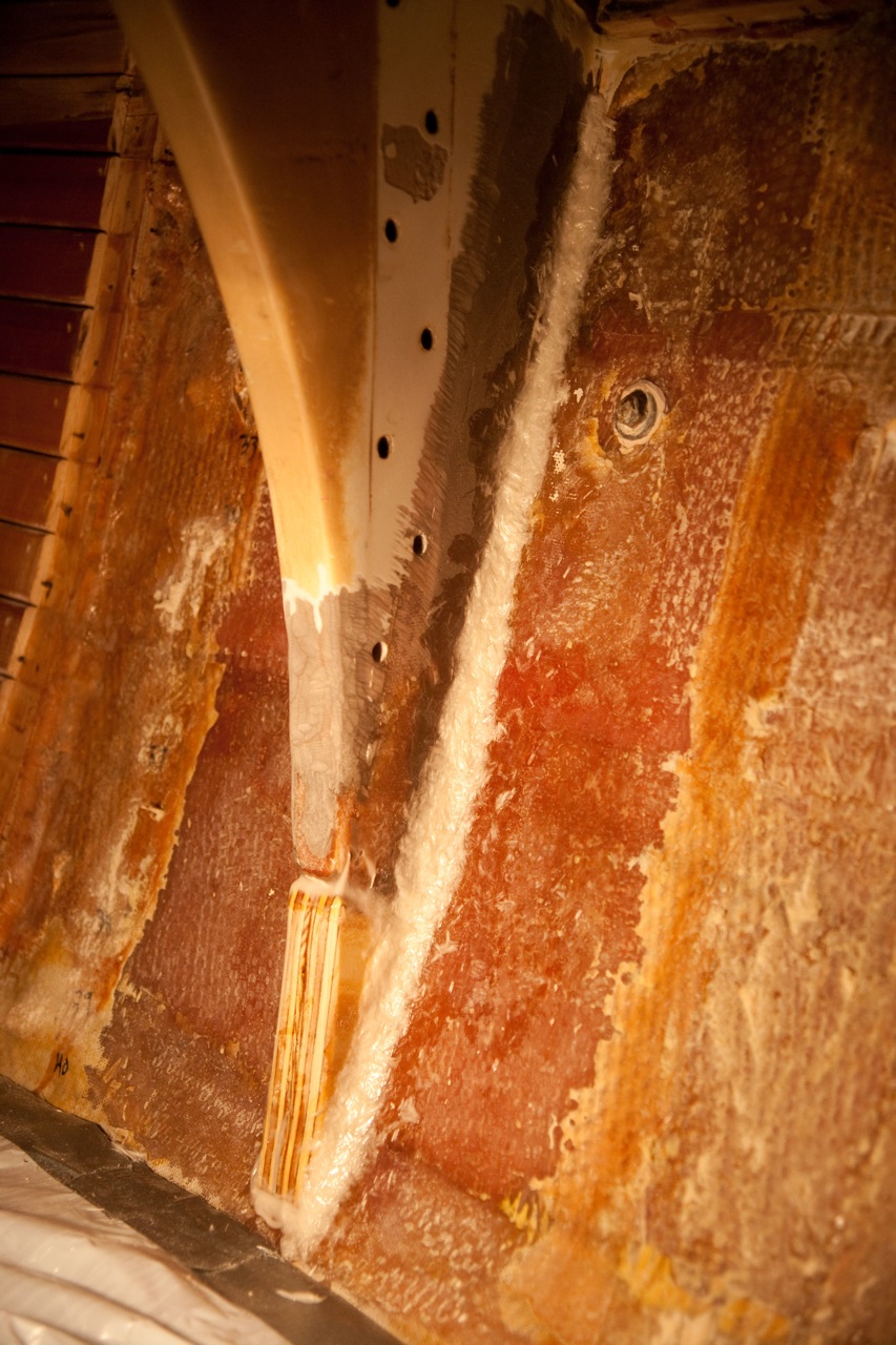
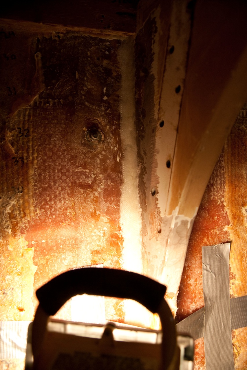
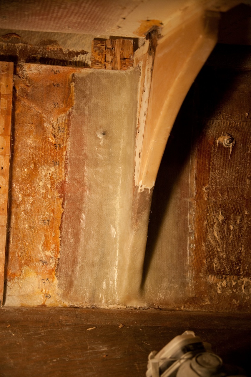
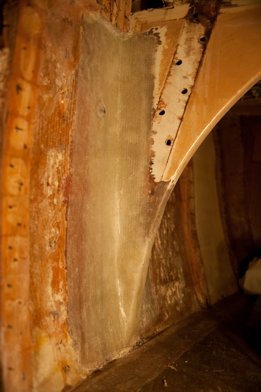
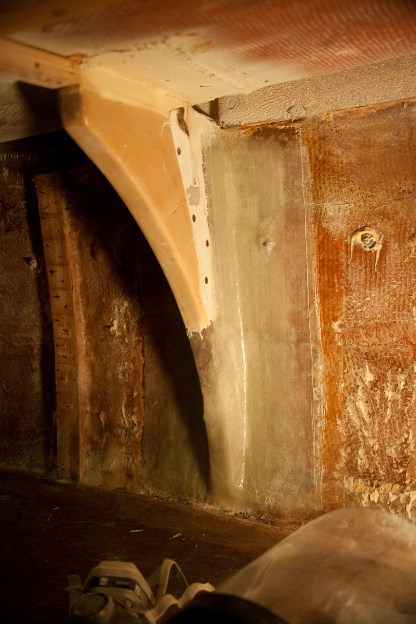
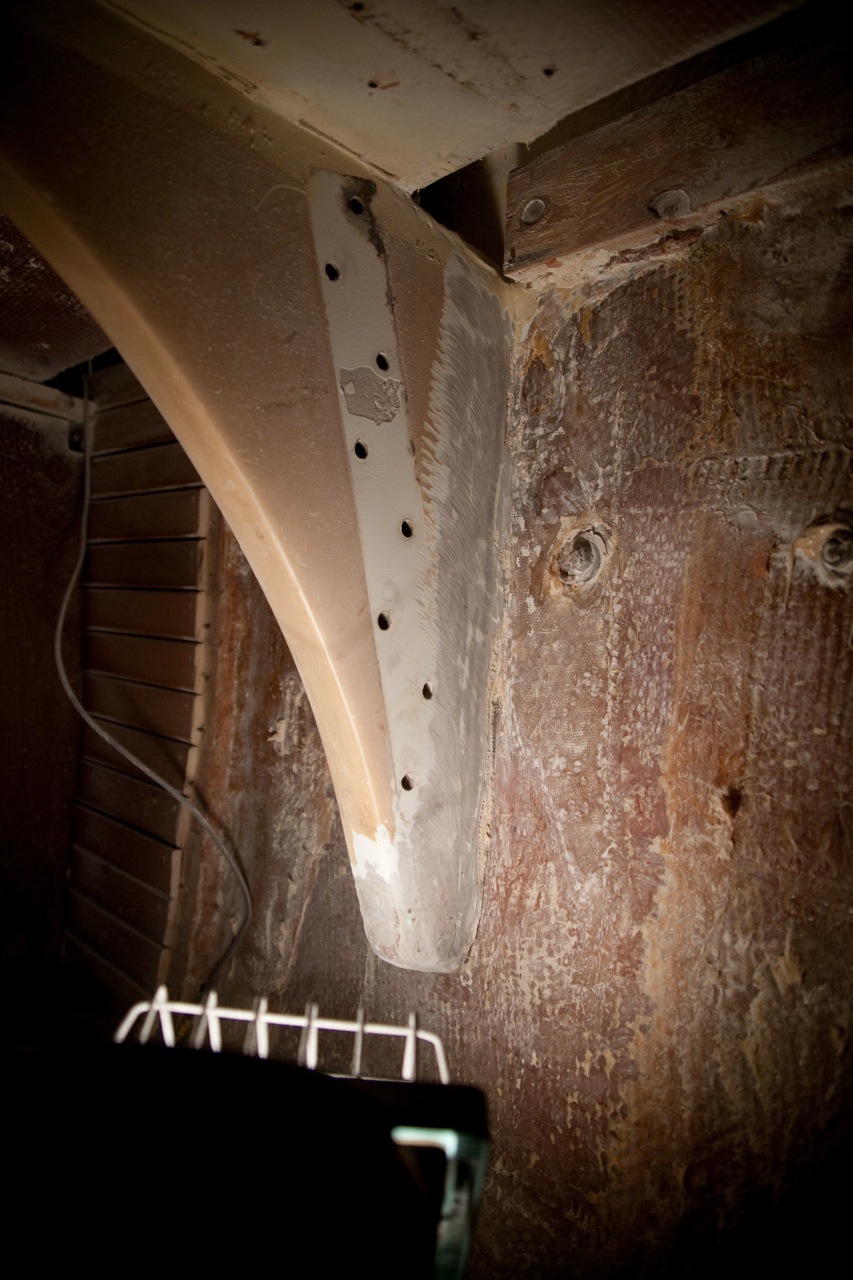
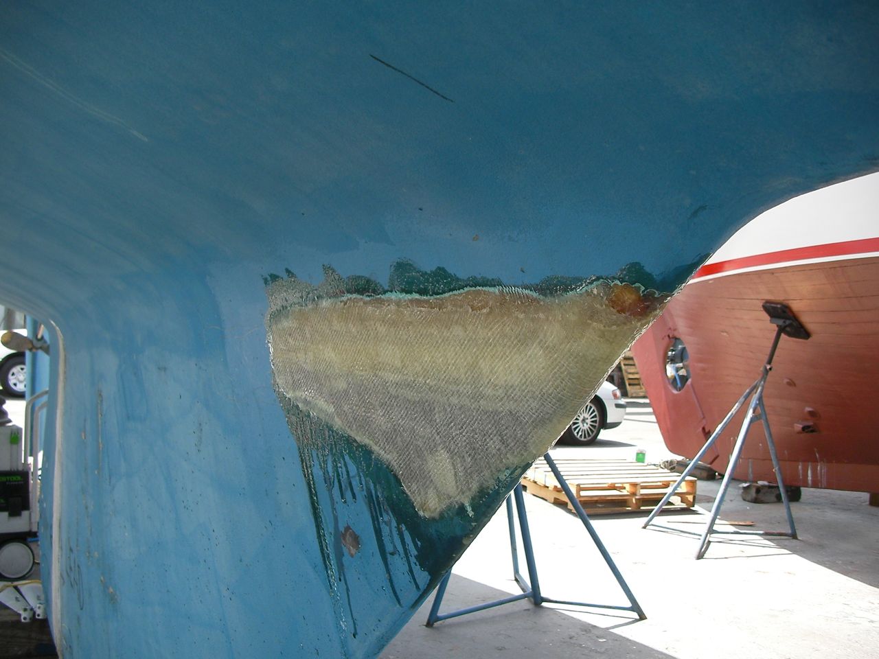
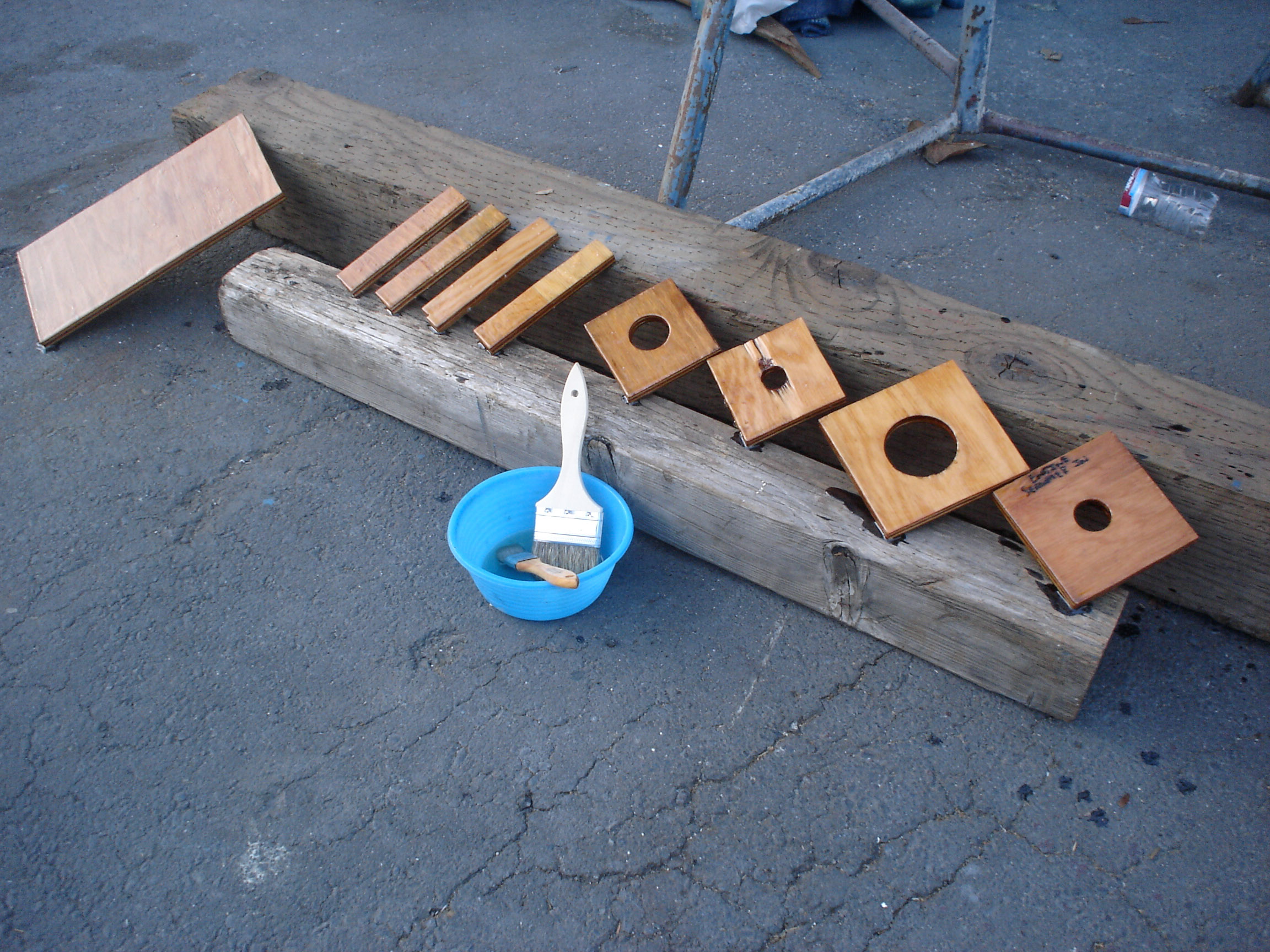
    As on the port side, I fabricated triangular extensions out of plywood to extend the knees farther down the hull.

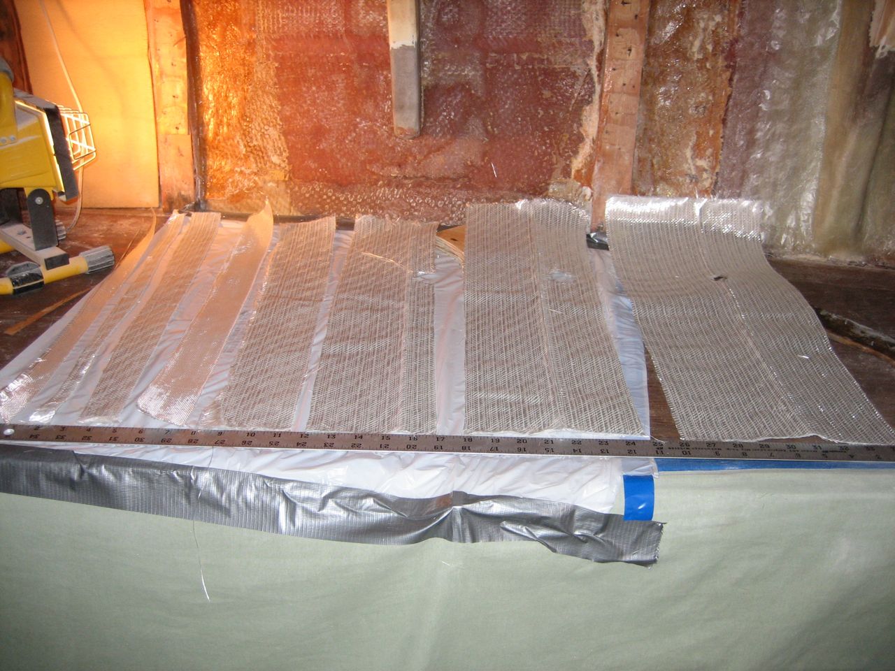
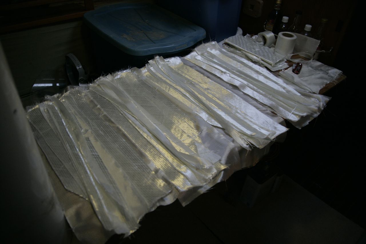
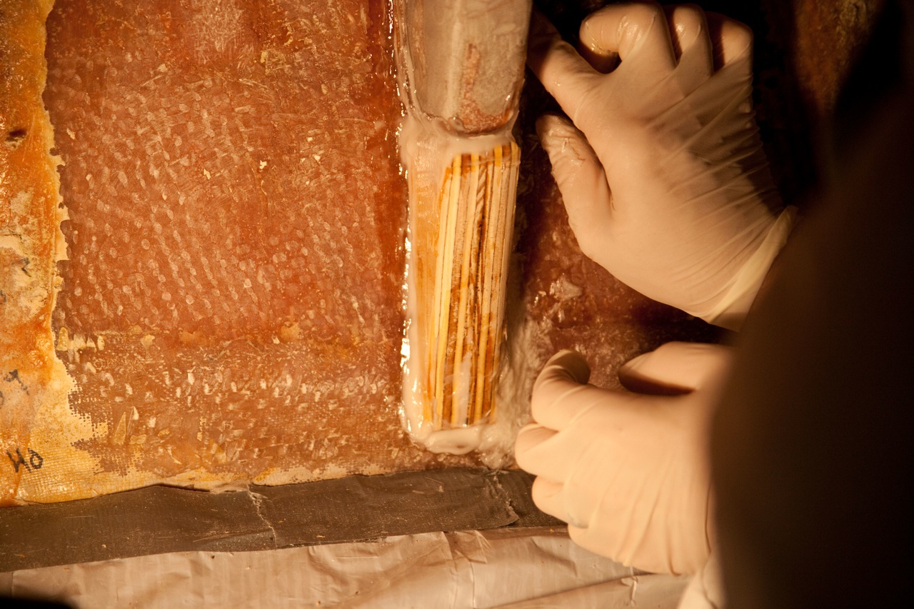
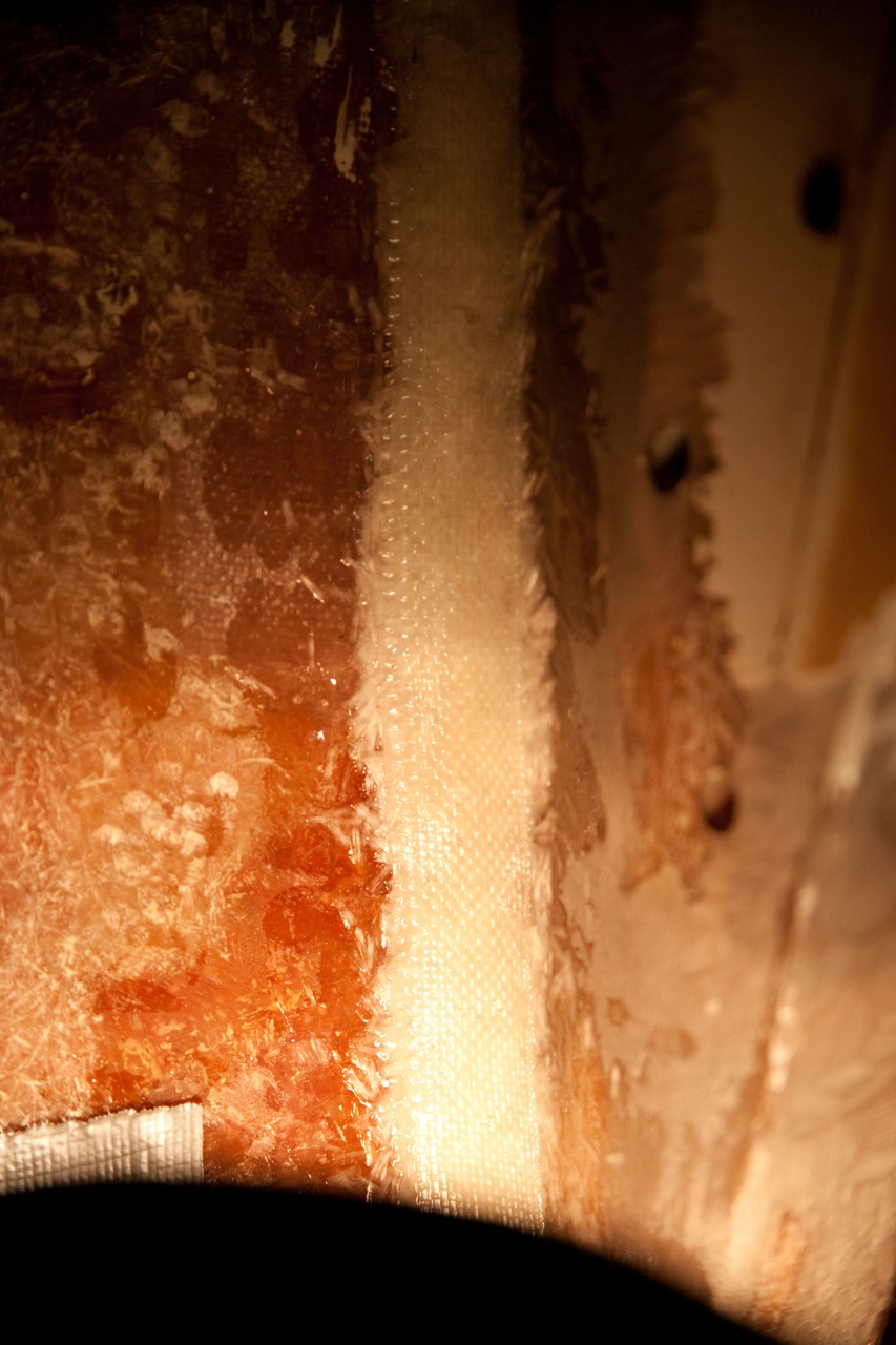
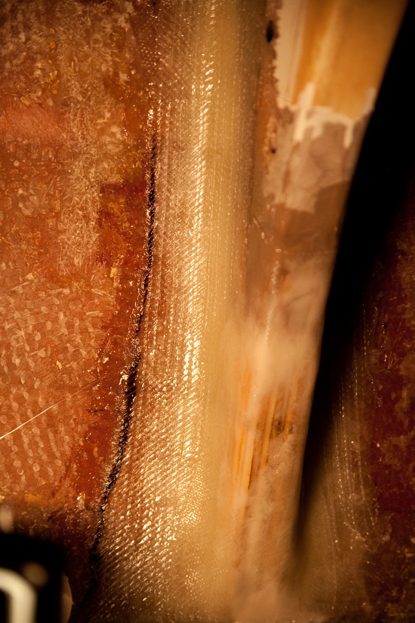
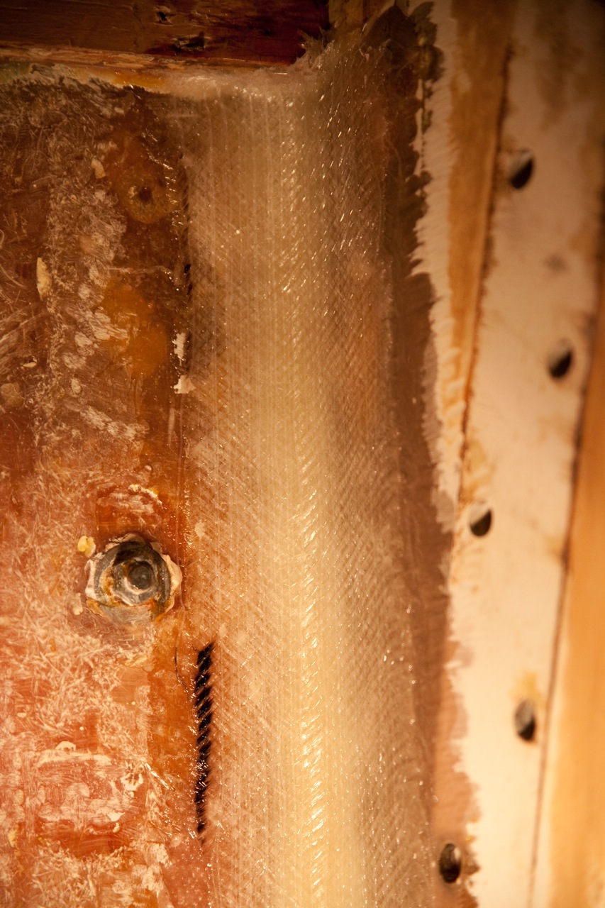
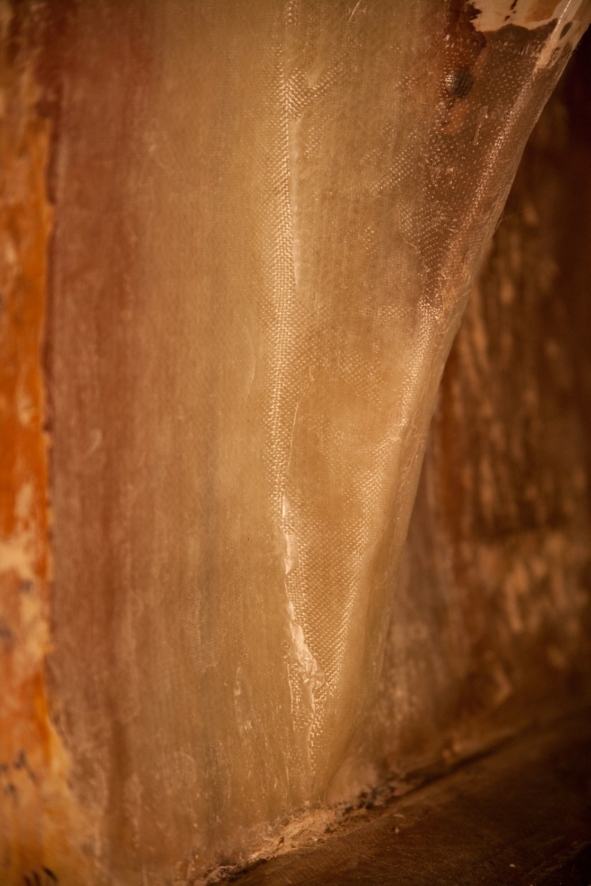
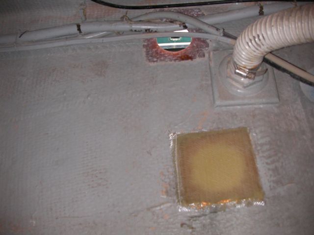
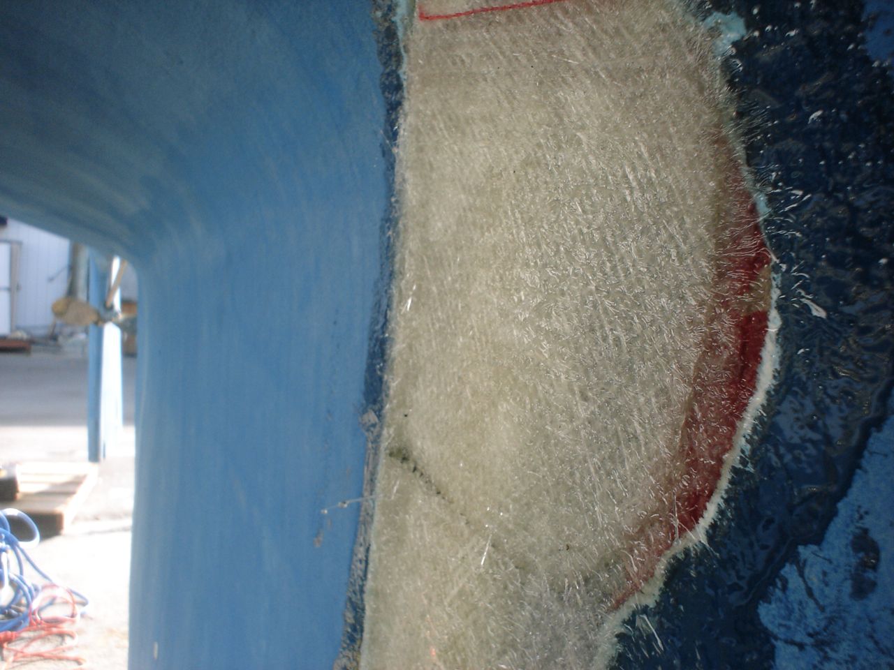
    I used the same method and layup as I did on the first knee (in part 2).

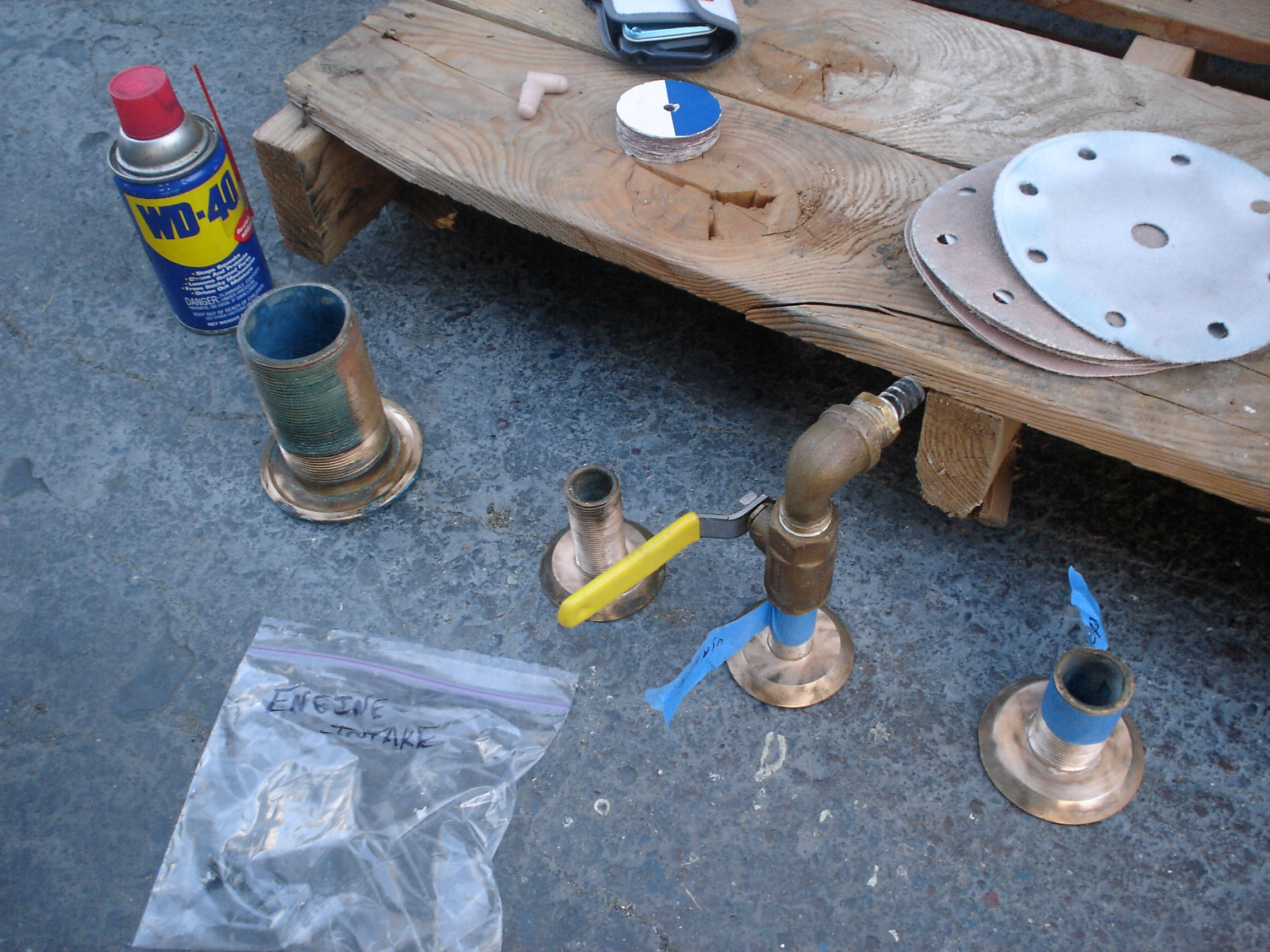
    As usual, putting it all back together took an eternity.

  • First knee reglassed (Knees Part 2)

    See knees part 1.

    Jon cut two triangles of 3/4″ plywood that I sandwiched together and used as an extension to the bottom of the knee–this was an excellent piece of advice I received from Paul Rosenthal (justifying the cost of having him out for a consultation by itself).  He also convinced me (or pointed out) that there was no good reason for putting a reinforcing pad of fiberglass between the knee and the deck.  As he explained, the deck should only take the load if the construction is wrong–the hull should be taking all the load.

    This was my lay-up (so that I remember two days from now when I do the next one):

    large fillet of epoxy thickened with chopped glass (a container of ready-made chopped glass from TAP plastics).
    Strip of 6oz glass ~1cm
    strip of knytex ~2cm
    6oz glass ~3cm
    knytex ~3in
    6oz glass ~5in
    knytex ~6in
    knytex ~7in
    knytex ~8in (4in each side)
    6oz glass ~9in

    The knytex is a layer of mat and biaxial fabric bonded together; it is thick and extremely strong.  It does not like to take corners at all–hence the thick fillet.  If not for the thick fillet, the knytex would pull away from the joint and leave a gap (and weakness).

    I think the job is strong enough.  I am not a fiberglass professional and so I worry about various things, like whether I use too much resin, and other small things, but until someone smarter tells me what to change I have to plow forward with what I’ve got.

  • Knees Broken (Part 1)

    My worst fears have come true: the raised lumps on the deck that we discovered while refinishing are caused by the knees, which have separated from the hull and are rotating up and pushing on the deck inboard of the chainplates.  Three out of four knees have ~1/8″ to 1/4″ gaps at their bottom ends, and the tabbing towards the bottom is colored white, further indicating delamination from the hull.

    We were intending to depart in January; I don’t see how that’s possible now with this job thrown into my lap at the last minute.  Karen and I just moved onto the boat, and I’m going to have to rip out the cabinets and do a massive fiberglass grinding and repair.

    I removed the slats that hide the port forward lower; I chose to tackle this one first because it doesn’t require removing cabinets to access it.

    I used plastic to tape off the entire area.  I wore a bunny suit, full facemask, and respirator.  I ground the fiberglass tabbing off until reaching clean, solid glass.  That part really sucks, the grinding.

  • Repainted bottom

    Jonny sanded the starboard side, I sanded the port side.  That took a day, and was tiring work.  We used the yard’s special vacuum sanders ($15 rental/day) which are required by law to help suck up the toxic old paint.  We went through a dozen 80 grit pads.  I spackled our keel fiberglassing projects with QuikFair, a really great two-part filler designed exactly for this task, and sanded it fair afterwards.

    Then we painted over all exposed fiberglass (from our various keel/through-hull projects), and the bronze skeg shoe, and the bronze shaft strut, with 4 coats of Interlux Interprotect 3000E epoxy primer. It is high build (read: thick).  It is my hope that this will both seal the fiberglass and help paint stick to the bronze.

    Then we applied 4 coats of Pettit Premium Antifouling Bottom Paint. It is an ablative paint, which means that it sheds off over time.  The previous paint was an ablative, and you can’t put a hard paint over an ablative, and we weren’t going to sand all the way down to the barrier coat, so it was an easy choice to pick an ablative.  The “Premium” that we got is one of the cheapest bottom paints available ($75/gallon); Practical Sailor gave it a best buy, and after reading a lot about the different bottom paints, I couldn’t shake the feeling that the expensive stuff is a hoax. We bought 4 gallons, and used 3.5 to do the 4 coats. Jonny and Karen did all the painting 🙂 lucky me.

    Four coats is maybe a bit excessive (most people do 2 or 3 at most), but we’re not going to save the paint for next time and the paint works by wearing off over time, so the more the better, right?  We didn’t bother trying to make it super pretty, but it came out pretty slick regardless.

  • Moved engine exhaust through-hull

    The through-hull was a few inches below the waterline.  The exhaust through-hull should never be below the waterline, for two reasons: 1) you need to be able to see that water is coming out of the exhaust, to be sure that raw water is cycling through the cooling circuit 2) there is greatly increased possibility of seawater backing up the exhaust and flooding the engine–which is a bad bad thing to do to an engine

    We moved the engine exhaust through-hull up above the waterline a few inches, and glassed over the old hole. The old engine through-hull had a janky fitting to connect to the hose, which was prevented from leaking solely from excess 5200. So we found a through-hull threaded on the bottom for the nut, with barbs at the top for the hose. It’s above the waterline now so we elected not to put a seacock on it.

  • Repaired delaminated rudder

    Our rudder delaminated (fiberglass pulled away from the foam) very slightly, no more than 1/8″, from sitting in the mexican desert where the sun would expand and contract it every day. I know that it happened there, because the yard workers repaired it and it sat for awhile without sailing, and it delaminated again while sitting there. The only really important issue is whether there is water in the rudder that is corroding and rotting away the internal metal structure. If that happens, the metal tabs inside can break off and you can lose your steering–which would be very bad indeed. There was no water in our rudder (well okay like two drops) so the delamination that we had wasn’t very alarming. But we repaired it anyway. We drilled holes and injected epoxy using a syringe, then filled the holes with thickened epoxy, and then eventually sanded these fair before priming and bottom painting.

  • Repaired keel damage

    Our keel is half lead, half foam. The front half is lead, the aft half foam. The problem with this is that the join between the two is apt to crack–the keel flexes, the yard sets it down on the foam, maybe even just sailing it, whatever did it, it cracked on us and was admitting/weeping water. (Sometime after our hull number, uniflite wised up and started making the bottom half lead, top half foam.) Down in mexico, I drilled a ton of holes into the foam, bottom and sides, in order to drain the water that was living in there. I also ground down the join so it could dry out. Also, the “smile” at the top front of the keel was weeping slightly from a crack in what I believe was the fairing compound they used. I ground this down in anticipation of drying it out and glassing over it also. In the Berkeley workyard we injected epoxy into the holes I had drilled to repair the mild delamination. Then we used knytex fiberglass fabric to glass over the join (many layers–I had gone a little overboard with the grinding). We glassed over the “smile” the same way. Then we ground down/sanded down the fiberglass fair with the hull. Then we used Quikfair (two-part epoxy fairing compound) to fair the areas smooth. Then we sanded these down fair. Then it was ready for priming before bottom painting. 


  • Through-hulls, Seacocks, Backing plates

    There were 8 below the waterline through hulls when we bought the boat: one for the depth transducer, one for the impeller transducer, two for the head, two for the galley, an engine intake, and the engine exhaust. Some of the through-hulls had seacocks, others had inline ball valves screwed onto the through-hulls. The engine exhaust had no seacock or valve. Only two (the head in and out) has sufficient backing plates. In all cases, the seacocks were not screwed down all the way to the hull; the through-hull nuts were screwed down to the hull and the seacocks were screwed on top of them.

    We added proper backing plates to every below waterline through-hull. The backing plates are 3/8″ marine grade plywood, saturated with penetrating epoxy to waterproof them.

    We installed flanged, ball-valve seacocks on each through-hull. The seacocks are lag screwed into the backing plates (not all the way through the hull). The seat for the lag screw was drilled out and injected with thickened epoxy, so that the lag screws are not penetrating into the wood in any spots.

    We ran into numerous roadblocks during these jobs. 1) A few of the old through-hulls were not long enough after adding the backing plate, so we had to purchase new ones, measure the amount of thread needed inside the boat, then cut off the excess (so the seacock will fully screw down to the backing plate). 2) After installing the backing plates in the galley, we discovered that they weren’t close to parallel to the hull, so jonny spent hours grinding them down to an angle so the seacocks would sit flat (see the video below). 3) All the old through-hulls on the boat were insets, with a countersunk flange. Unfortunately, the through-hulls at Svendsens has differently shaped flanges. So we glassed over the two head through-hulls (you can see this in the third picture below), drilled out new holes, and then used standard mushroom through hulls. This ended up taking far longer (the glassing part) than I thought it would. In retrospect, we should have shaped the old insets to accomodate the flanged through-hulls that we could buy at Svendsens, using the dremel and/or thickened epoxy to make a new seat. 3) It took some time to mark where the lag screws would go, drill out oversized holes, fill them with thickened epoxy, remark where the lag screws were to go, then drill pilot holes for the lag screws.

  • Serviced Packing Gland

    When we did the sea trial, the shaft seal leaked.

    We have a PSS shaft seal, which is a purely mechanical seal that doesn’t require any sort of packing as in a traditional packing gland. It consists of a stainless collar that is pressed against a graphite fitting. The idea is that it’s slippery, sealed, and doesn’t heat up. Here’s a diagram from the excellent “How Boat Things Work” by Wing.

    On the sea trial the shaft seal leaked slightly at an idle, and more so as the engine was brought up to operating speed.  During the xmas work trip Jon tackled this job. Loosen the set screws, slide the collar up, figure out how to reach in there to clean it, push the collar back down, tighten, easy. The only tricky thing is that after many years, the rubber bellows loses it’s elasticity, so we were clueless as to how tight was tight enough. We just pushed the collar as tight as we could and locked it down. When we ran the boat in february, it didn’t leak.