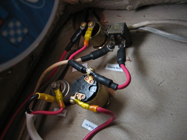
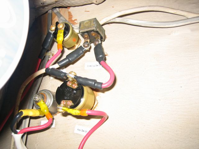
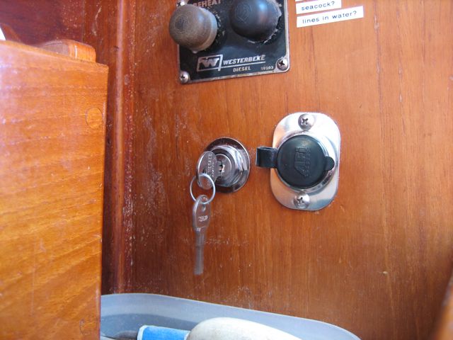
The old ones had to be jiggled and messed with to get them to work, bad connections inside. I replaced both switches, and all the wiring behind them.
The old ones had to be jiggled and messed with to get them to work, bad connections inside. I replaced both switches, and all the wiring behind them.
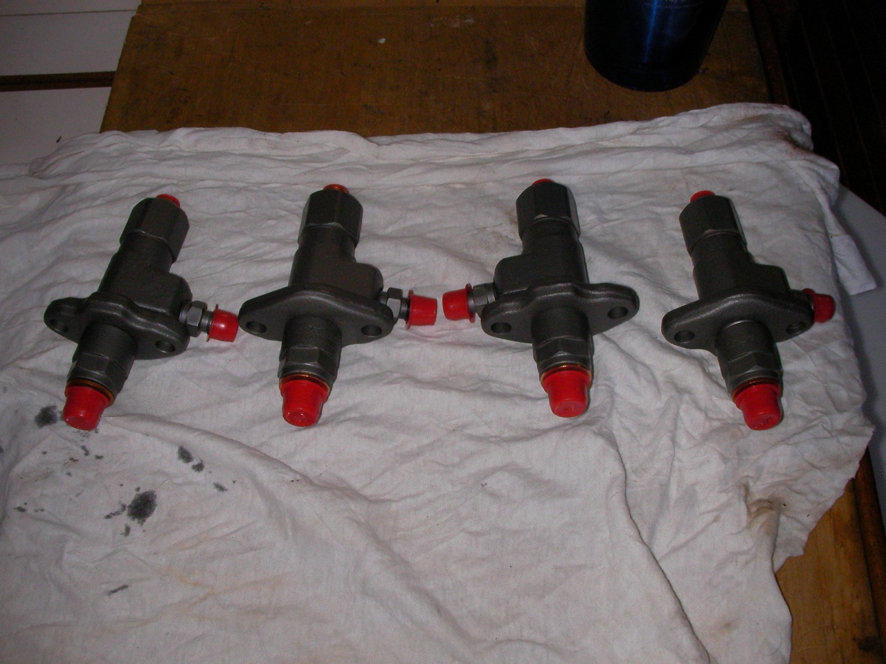
Well, we didn’t do it. Diamond Diesel in Oakland did it, and did an excellent job with quick turnaround for $80/injector. And when I took them in they let me watch as they tested them for free (and I could see exactly why they needed to be rebuilt).
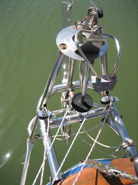
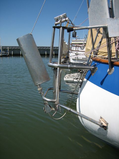
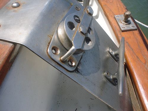
Boy was this a task. It was vintage 1989, and it was in tatters. One of the supports broke off under my weight one day, nearly dumped me in the drink. The chain broke off in my hand. Then we tried to take it all apart, and half a dozen bolts and things sheared off. Some of the tubing had rotted (I didn’t even know 304 stainless could rot, but that’s sure what this looked like.
Conveniently, Scanmar is located just 10 minutes away in Richmond. I went up there with the monitor in pieces and carried it inside, and they had a grand time poking it and giving me fantastic advice on how to restore it to pristine condition.
I took a piece of it back home to my dad to weld this past christmas (before I learned how to myself). I did a post about it on the syzygy site.
We spent $600 on new parts–everything that wasn’t in excellent condition was replaced–and put it all back together fastidiously (do I know any other way?). Everything is as frictionless as possible and as tight as possible (with out binding). And ready to go.


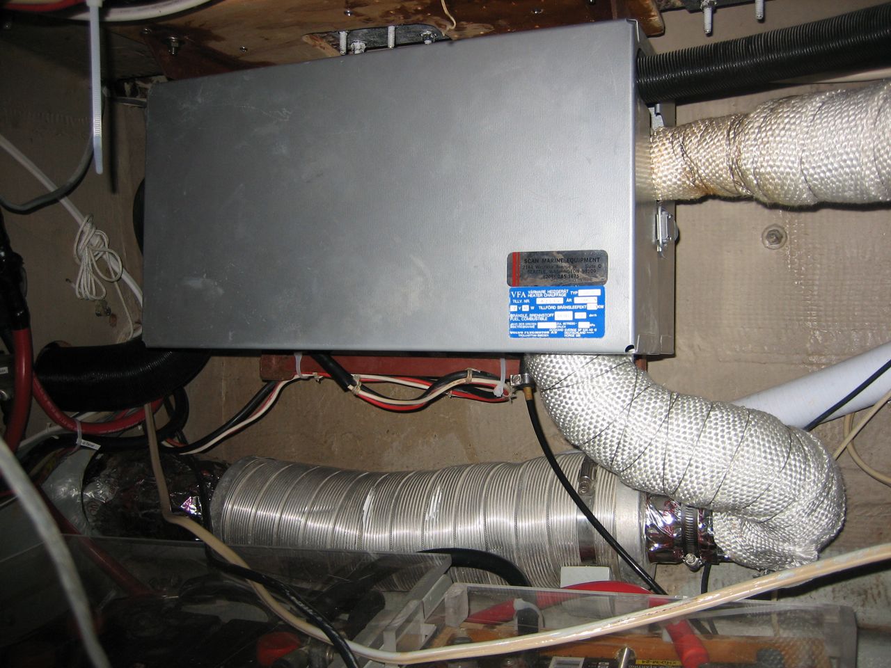
Carriage bolts were sunk through the deck to mount the heater. This is the perfect way to mount it–if you want to guarantee that it will leak and rot your deck. I constructed a mounting plate from 3/8″ plywood, epoxied some countersunk bolts through it, and epoxied it to the ceiling of the engine room with thickened epoxy. I managed to move it back into the corner more in the process, gaining us some extra room.
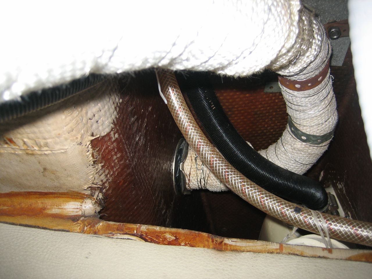
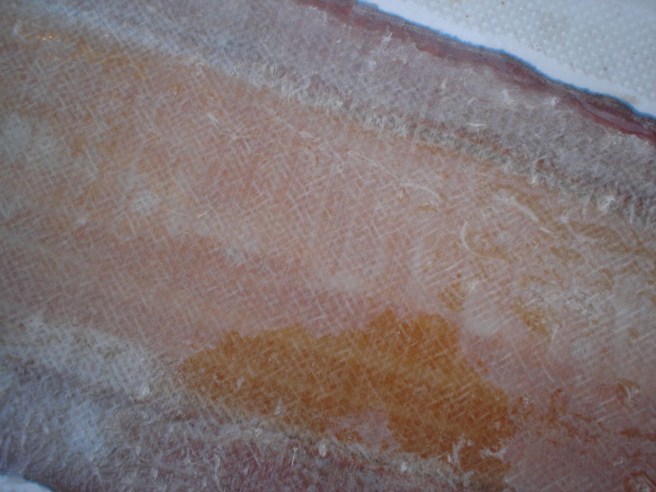
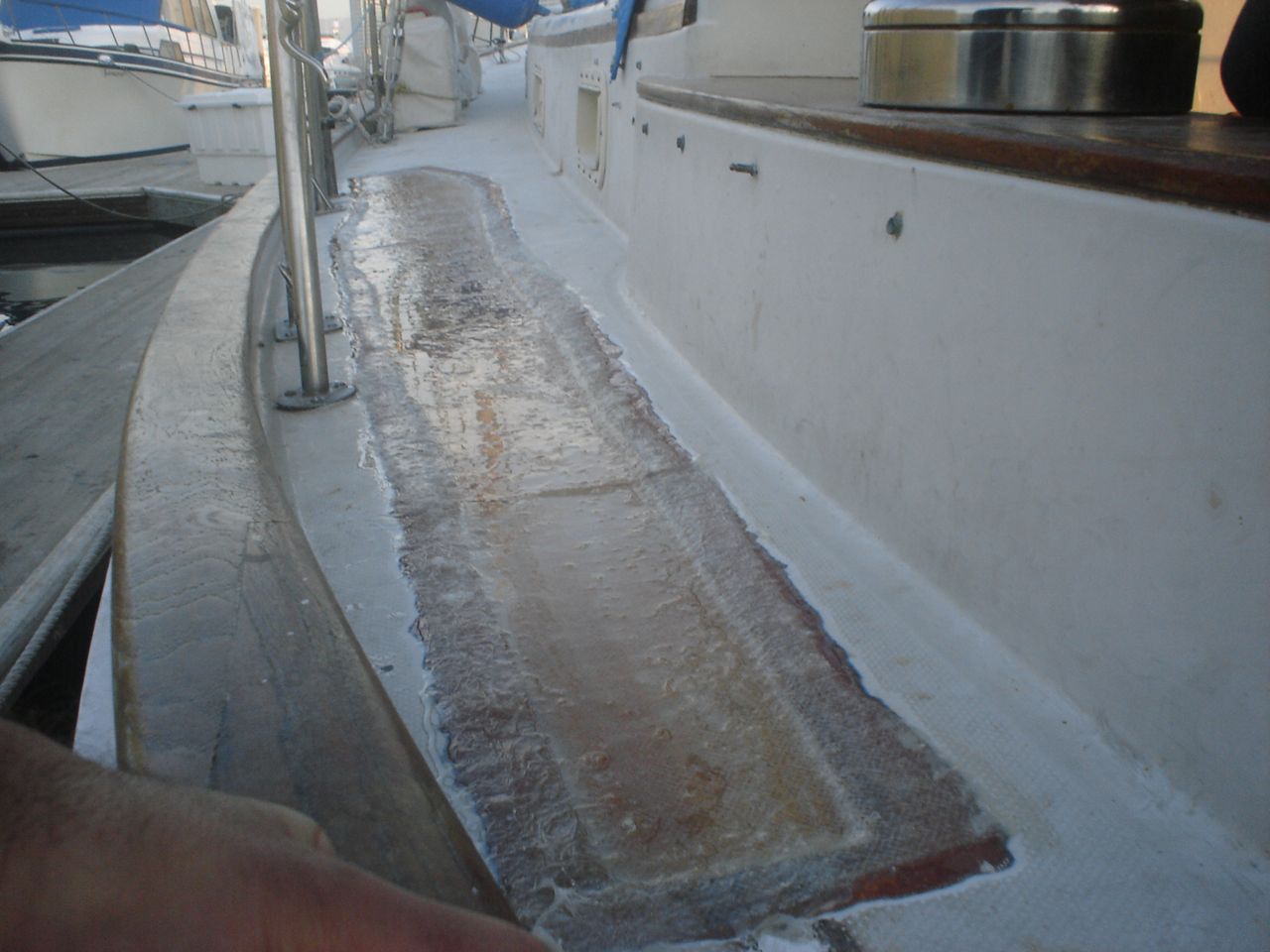
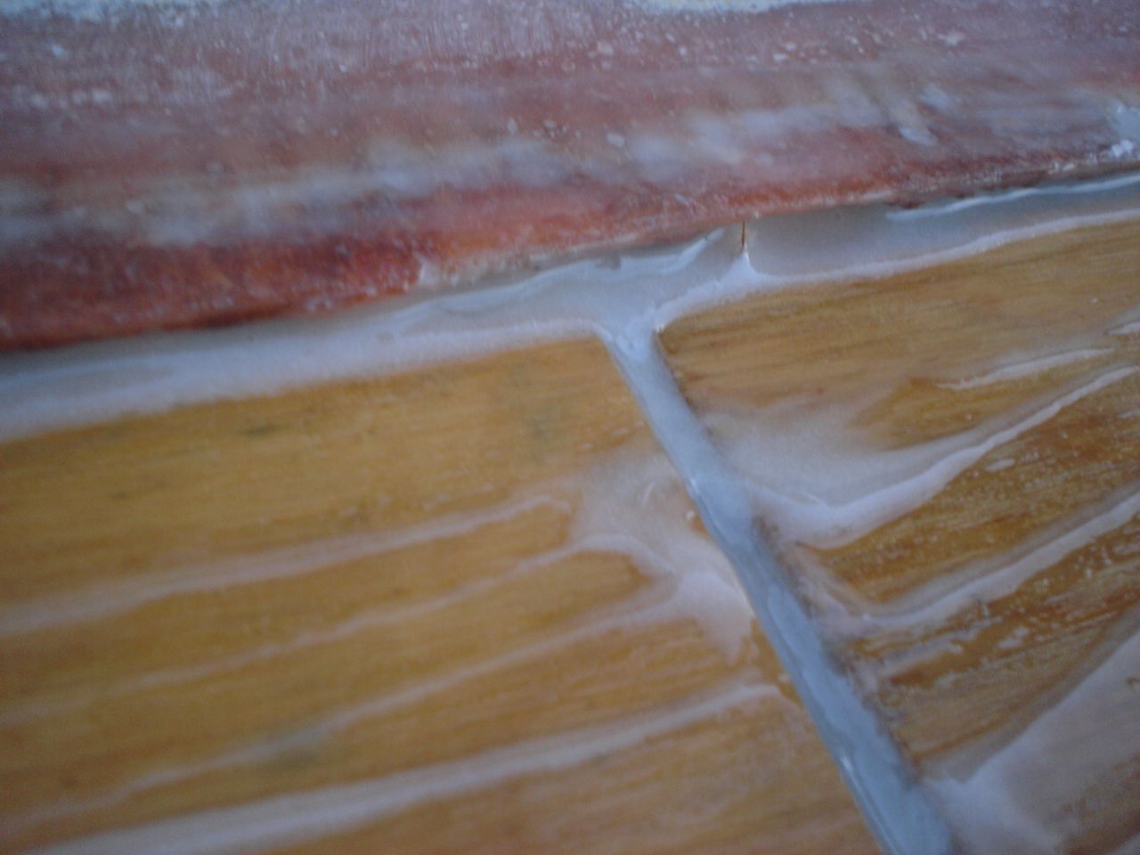
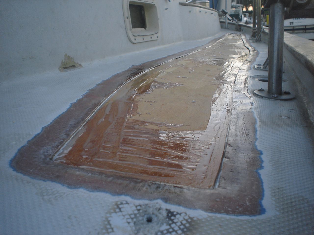
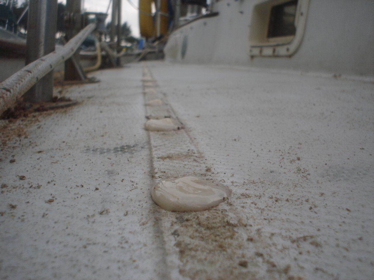
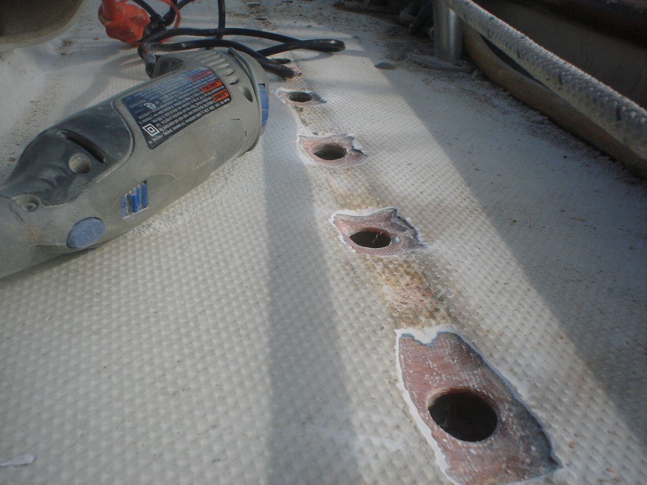
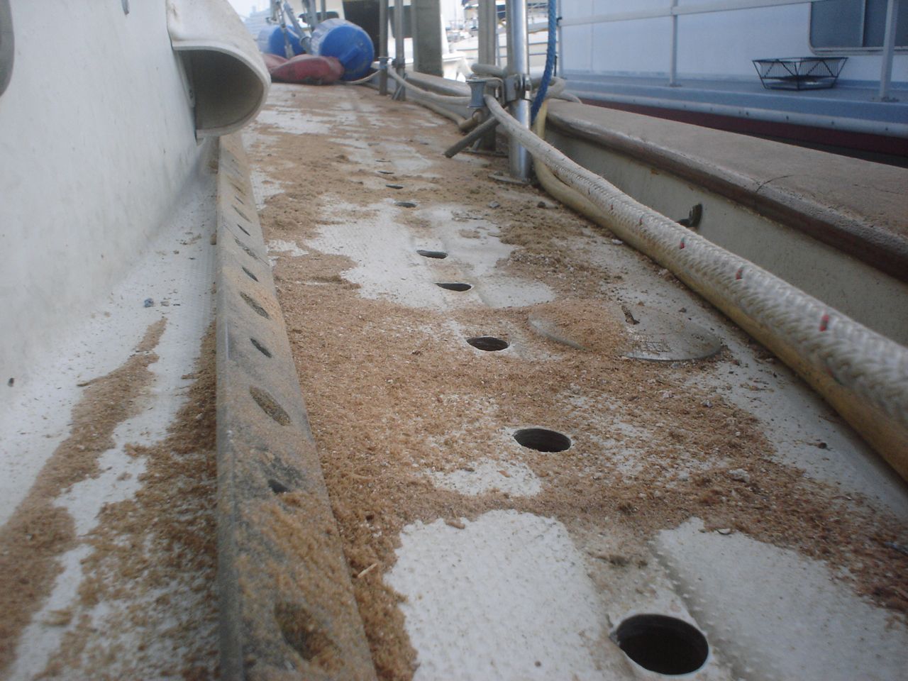
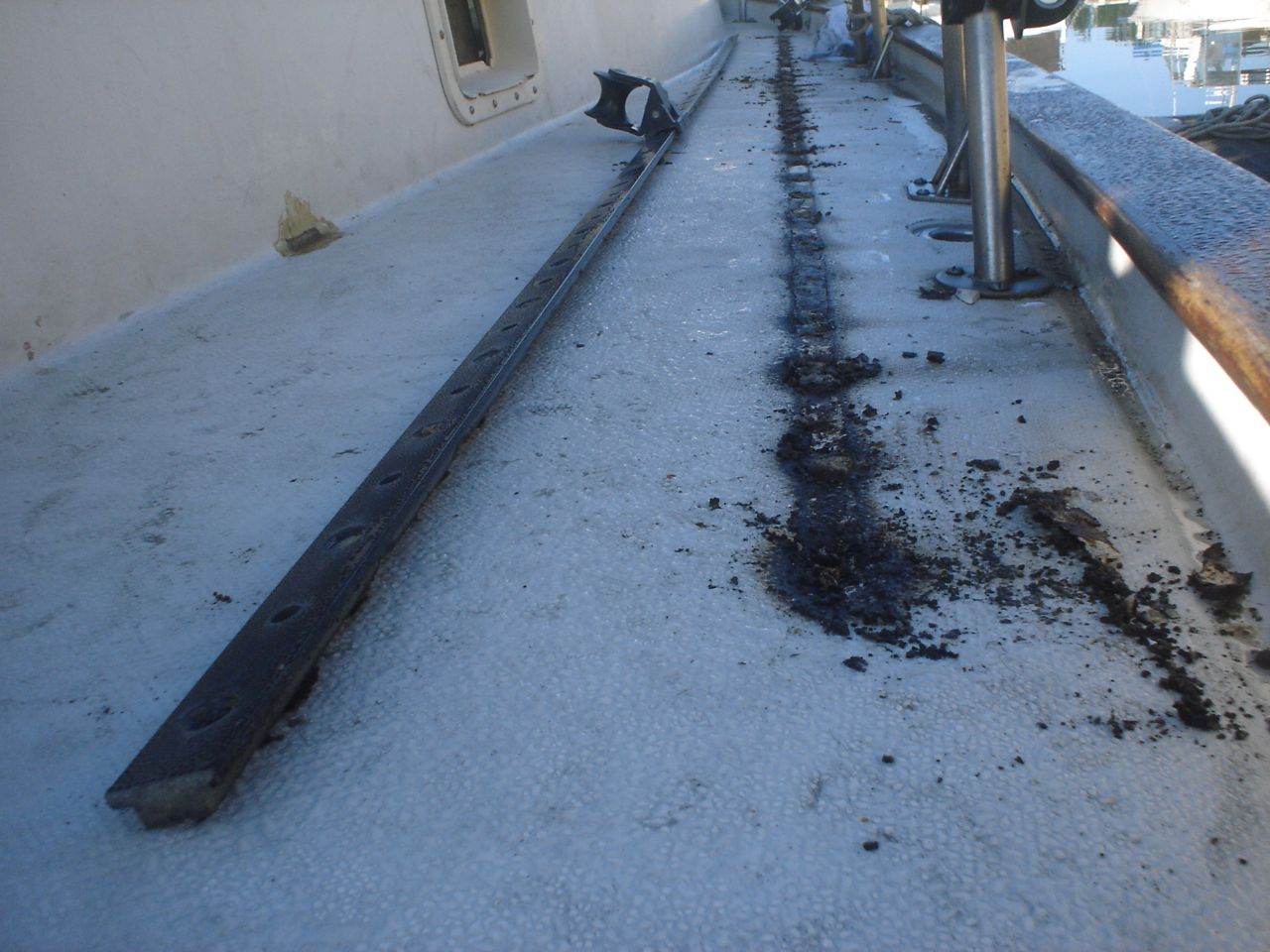
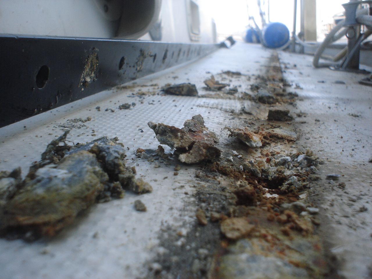
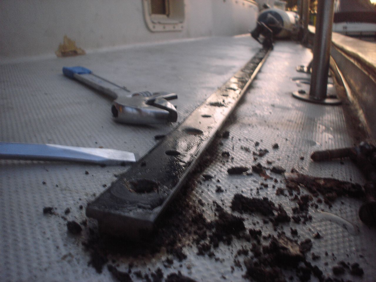
We traced a bad leak in the quarterberth to the port side track, and it was bad enough to need to be addressed immediately. Jonny pulled up both tracks. On the starboard side we got away with drilling, coring out the balsa, and filling the plugs with epoxy before redrilling new holes and mounting the new track from Garhauer (1-1/4″ 10′ long). On the port side we weren’t so lucky. Jonny discovered that a 1′ x 10′ section of the balsa was rotted out, so he cut the top side of the deck off, chiseled out all the balsa, cut a new piece of marine plywood to fit, and glassed over the top with epoxy and knytex (great fiberglass available from TAP plastics–layer of cloth backed stitched to mat–good for building up thickness fast). I laboriously ground down and faired it afterwards (Quik Fair is my fairing product of choice for this task). Initially I was trying to do my grinding with a grinding blade on our 4″ grinder, but the radius is too small for quick, pretty work. So we bought a variable speed 5″ Milwaukee grinder, took the guard off, and put a 7″ sanding disc on it. I bought some 36 grit discs for it, and ran it at low rpms. This is DEFINITELY the tool to use for this job. We painted over the work with a two-part epoxy primer and we’ll finish the rest of the painting, etc when we get around to doing the rest of the deck.
Finally replaced (I should say “installed” because nothing was left of the old one) the zinc in the heat exchanger. I’m ashamed that it took us this long, since we may have contributed to the disintegration of our heat exchanger, but all I can say is that we’ve been heavily occupied with other things.
There is a zinc in the seawater side of our heat exchanger (on the side).
There is a drain plug in the coolant side of our heat exchanger (on top).
There was a drain plug in the bottom of our oil cooler; I replaced it with a threaded plug that holds a zinc.
There is a drain plug in the transmission oil cooler. I would like to replace this with a threaded plug that will accept a zinc.
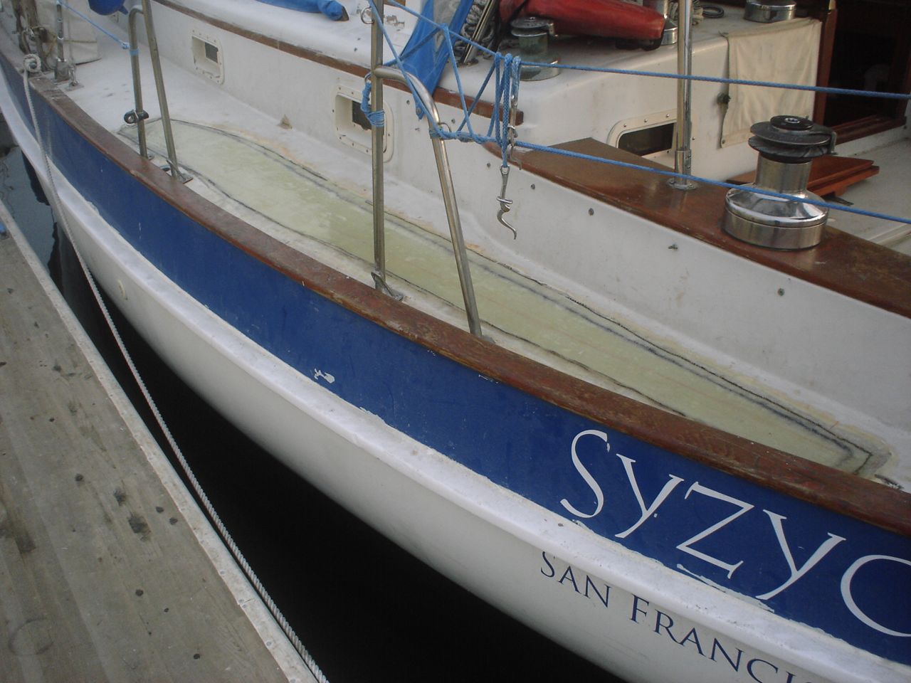
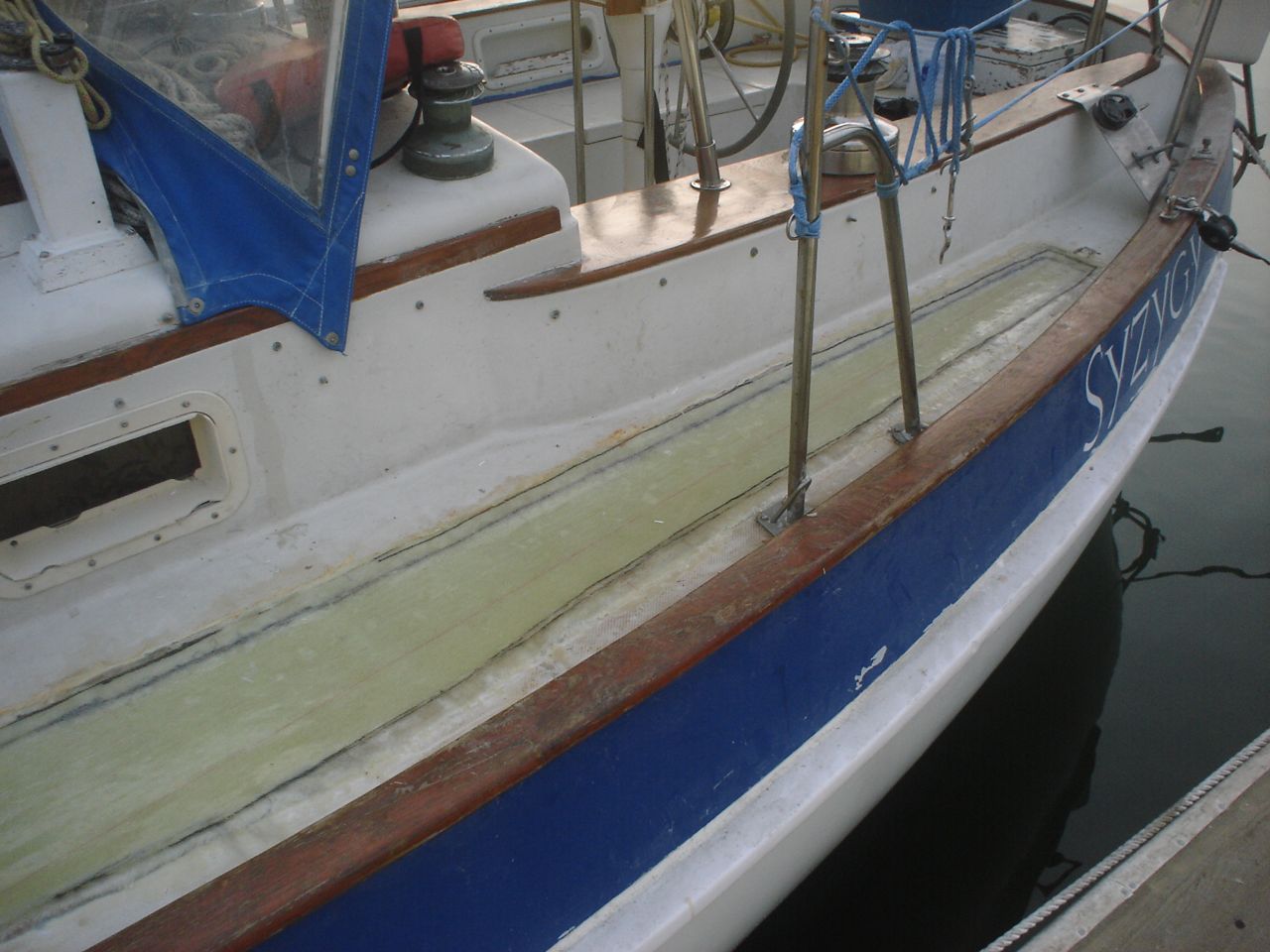
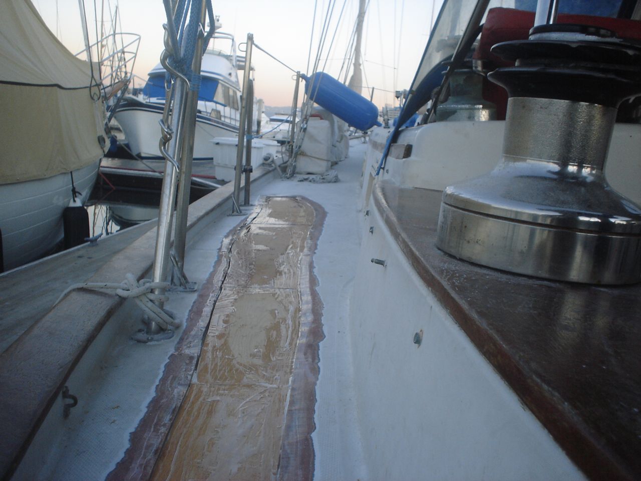
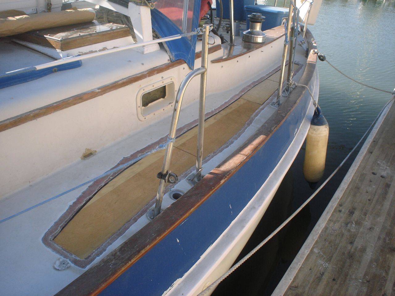
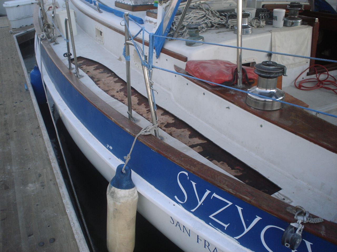
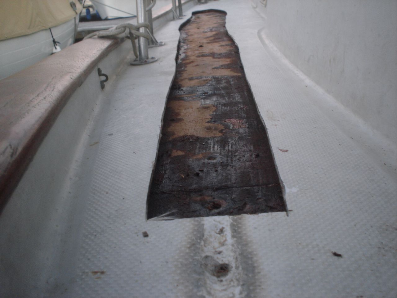
The rubrail is the wooden strip along the side of the hull that acts as a bumper. For some reason, the Valiant factory built the rubrail out of two strips of fir closest to the hull, and a strip of teak on top of those. Fir is not so waterproof. The previous varnish was peeling up, etc, and the fir was rotting in a handfull of places. Water was wicking down the gap between the wood and the hull, and rusting the bolts that hold it to the boat. It was time to take care of it, before more drastic repairs became necessary. Aside: there was no worry of the strength of the rail-hull connection. Valiant used a bolt every foot to fasten that rubrail to the hull, so a few rusting bolts is no concern.
We elected to paint the rail rather than varnishing it, for two primary reasons: 1) varnishing is way more work, both in the beginning and ongoing maintenance, than paint 2) after filling the rotted areas with filling compound, varnishing over them would not have resulted in a particularly pretty final appearance, which is half of the purpose of varnishing
This was our workflow:
1) Strip off old varnish with heat-gun and scraper (get a good scraper, it was worth every bit of the $30 I spent)
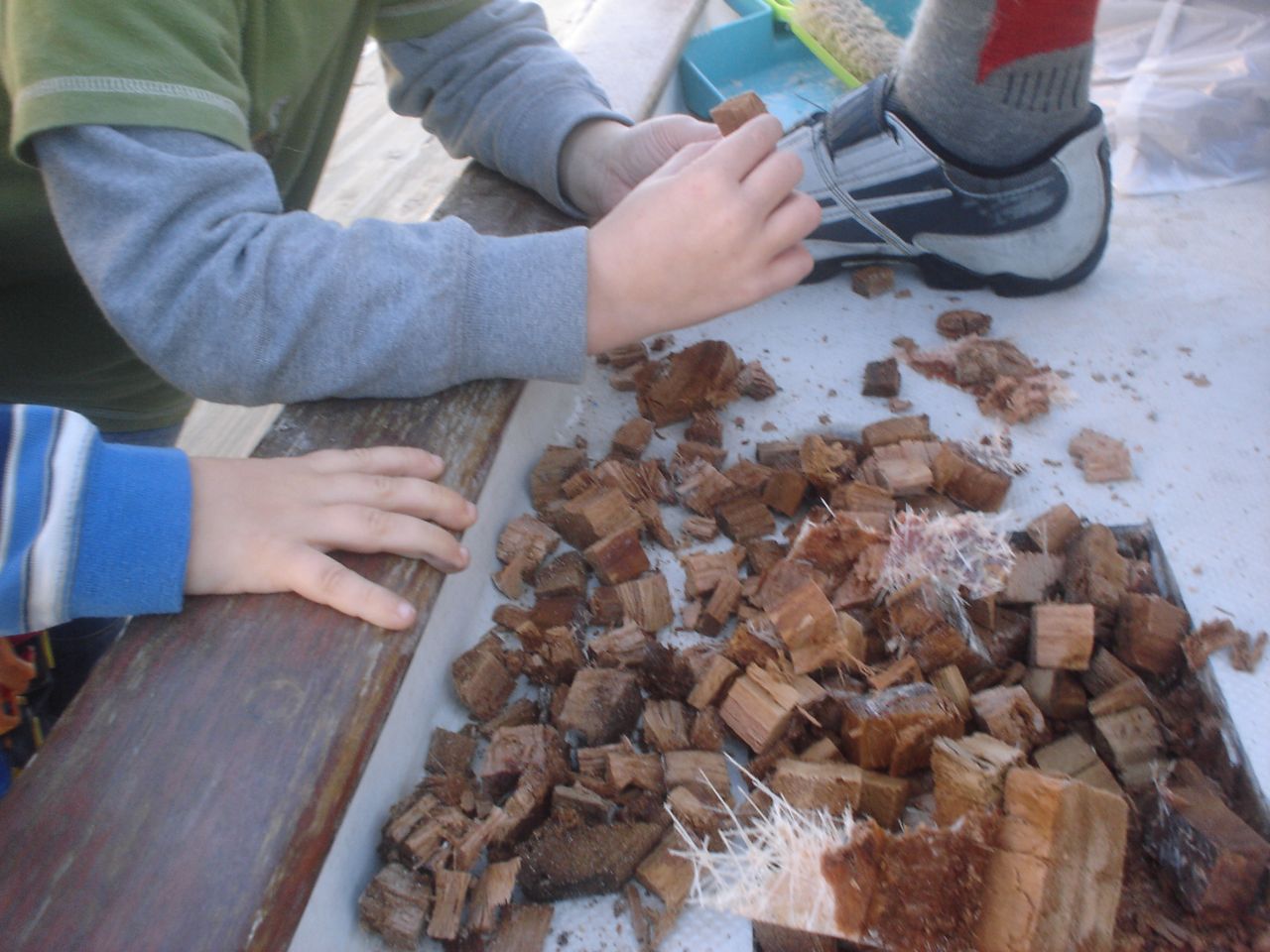
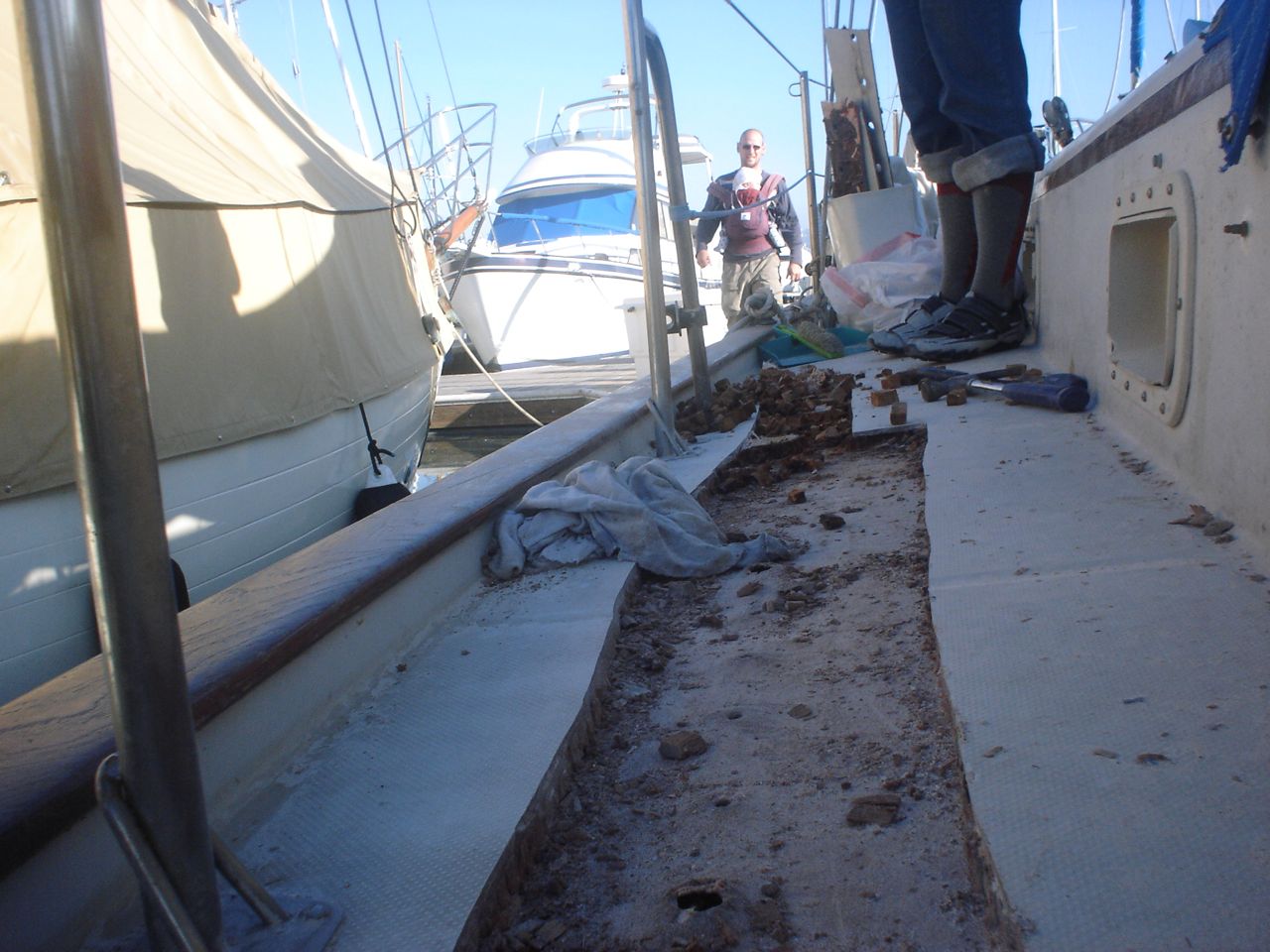
2) Dig out rotted, soft areas as best as possible with scraper and chisel
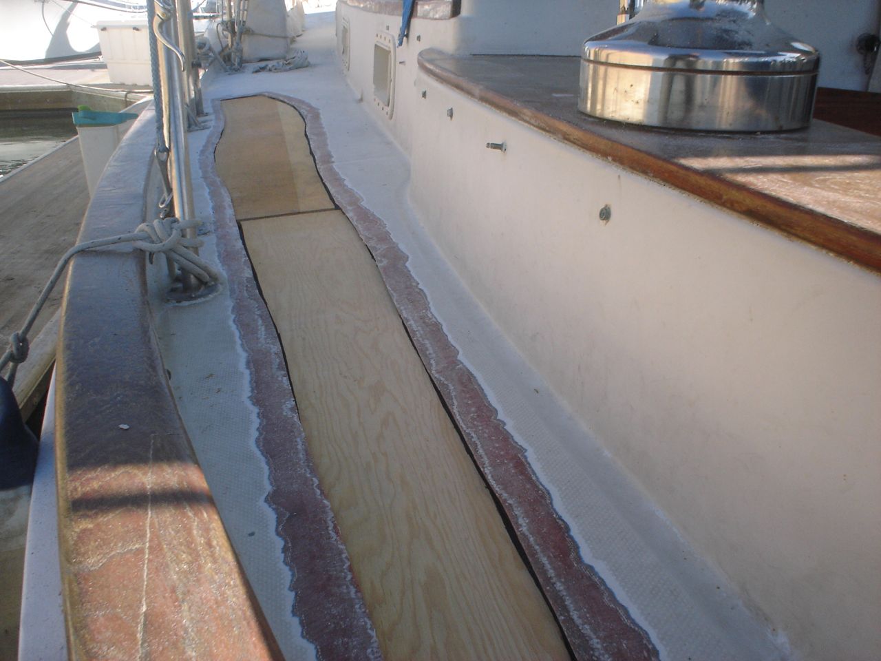
3) Sand with 80 grit. Buy and use a Fein Tool! Damn that thing is sweet.
4) Soak rotted areas with penetrating epoxy (i don’t recommend this step, it was a mistake, more below)
5) Fill rotted areas, voids, low spots, etc with QuikFair, which is a two-part epoxy fairing compound. QuikFair rocks. It is easy to mix, a perfect consistency to spackle on, and a pleasure to sand afterwards. We were in a rush and only did one round (one application of quikfair, then sand). I recommend leaving the time and finding the patience to go through at least one more round of fairing–after sanding down the quikfair the first time you’ll find that it didn’t get perfectly flat and smooth, so fair it and sand it again.
6) Sand with 120 grit
7) Apply Interlux Primekote. It’s a two-part epoxy primer that goes on really thick. Probably too thick–we probably should have thinned it some. But it is supposed to go on thick, and seal. We put it on with the intent of really waterproofing the rail. I would definitely recommend an epoxy primer like this one, for this job.
8) Sand 220 grit–since the epoxy primer didn’t self-level very well, there were some ridges and high spots to sand down fair
9) Paint 3 coats of Interlux Brightside, sanding with 300 grit between coats (just for giving tooth for the next coat). We did not thin and it didn’t seem necessary, but be careful it sags pretty readily, even out of the can. Meaning that you’ll put on what you think is a normal amount of paint, and then 10 minutes later you’ll see that it’s running down the side of the hull on you, and you’ll wish you had spread it out more.
10) On top of the second coat and the final coat, shake on non-skid beads (Interlux Intergrip, or whatever). We want to be able to stand on the rubrail without slipping, and the nonskid had the added benefit of cutting down the gloss–the rest of our boat is worn down, dirty, and dull, and the gloss was starting to make the rest of the boat look bad.
11) Lay bead of 4200UV down the top seam. The paint did a good job of sealing the crack–for now. I didn’t want to take any chances, because you know that it will flex and soon enough there will be space at the joint again for water to wick in. I was planning on using lifecaulk but Wally Bryant headed me off just in time–because that spot needs a product with UV inhibitors, like 4200. Since we’ll have to strip it off and renew it eventually, we elected not to use 5200 (which is effectively a permanent glue).
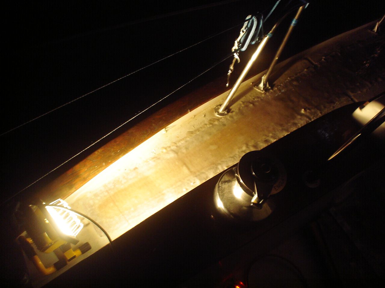
I’m fully satisfied with the result. It looks good and it certainly does the job (it’s protected). Jon sort of misses the wood look, but agrees with the wisdom of painting it.
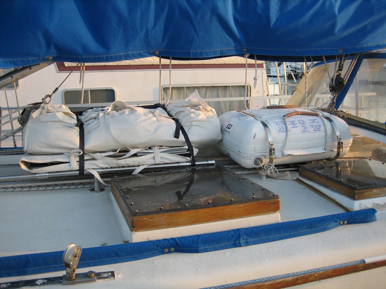
The dinghy is large heavy and unwieldy, and we had no place to put it except the floor of the cabin. We wanted to put it on deck. Turned out the most efficient use of space was to move the liferaft cradle aft, just forward of the dodger, then install steel tubing for the dinghy in front of that. The hardest part of the whole project was gaining access to the underside of the holes, inside the cabin. It was a pain in the ass to remove all the necessary ceiling panels, pull out the foam, cut out squares in plywood where necessary, and in one spot even relocating some wiring to make space for the bolts to come through. For every hole we cored out the deck, filled with a plug of thickened epoxy, and redrilled the holes down through the center. When we put it all together we used lifecaulk as our sealant. Jonny built the new dinghy cradle out of 316 stainless tubing and fittings (a shout out to Marcus, a marina friend, for helping source the expensive stainless). The result looks really sharp and is completely bombproof. We found a location for all of the mounts that doesn’t foul the running rigging (which all runs directly under both the liferaft and the dinghy). We made the dinghy cradle wide and long enough so that it was easy use simple webbing cam straps to hold it down.


We have 9 of the pricey and wonderful AlpineGlow light fixtures (came with the boat). These lights are dual function, white and red. The white light is a low-power fluorescent tube, then and now. They used to make the red side out of a flourescent tube covered with red varnish; nowadays they build them with red LEDs. The red varnish was flaking off all of ours, so I went ahead and replaced the red tubes with red LEDs. It was a bit of a wiring job, but made easy by the straigtforward conversion kit that AlpineGlow offers (for $15 each). The new red LED uses so little power, it barely registers on the voltmeter (about a tenth of an amp; compare that to a standard 12V incandescent bulb which is roughly two amps). When we turn on all the red lights, our cabin looks like the battle room of a submarine.
Additionally, three of the ballasts were bad, so I replaced those as well.
This deserves a post of its own, even though it was just a big clean up project.
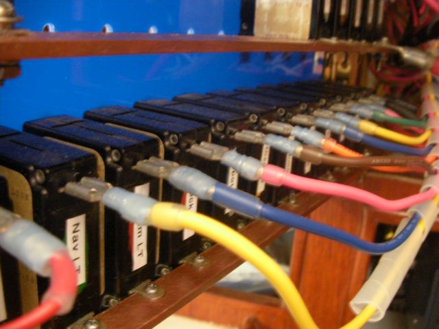
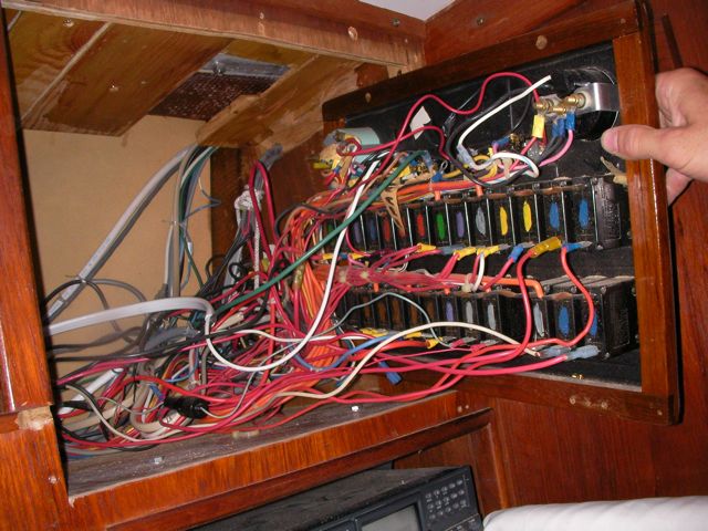
When we purchased the boat, I was most overwhelmed by the wiring of the boat. It was utterly undecipherable to me, for months. I spent hours looking at the original engine wiring diagram from Perkins, and the regulator wiring diagrams from Quad Cycle (no longer in existence, which didn’t help things). Hours staring at the engine and cursing in frustration at the dozens of identical looking wires wrapped up in duck tape (rendering individual wires untraceable). Yet more hours drawing up new arrangements and placements for bus bars and terminal blocks to organize things.
In the process of figuring it out, I discovered that it was made more confusing by a ton of extra, old wiring that lead nowhere, and also by some really fucked up wiring choices that had a single wire crisscrossing the engine room multiple times unnecessarily. Piece by piece I discarded unneeded stuff. There were two really big days, where I tossed enough garbage wiring out of the engine room to make a big rats nest pile in the cabin. The old engine wiring was completely encased in ancient black electrical tape, which was all gooey and black, and all of the wires running to the instruments were at least 8 feet too long (no one bothered to shorten the wires as it came from the engine manufacturer, I presume). The key switch, which is less than 3 ft away from the starter battery, was pulling it’s power from the starter solenoid across the room; twice a hot wire went an additional 4 ft past a perfectly functional terminal block, to be spliced into the middle of another wire directly under the wettest part of the engine. I discovered the original alternator regulator hidden underneath the solenoid, with much of the wiring still spliced in place all over (this despite the fact that we have a nice regulator mounted elsewhere, with a backup regulator mounted right next to it). The list goes on, but you get the idea.
Now it is organized, with clean connections, in the simplest arrangement that I could come up with, and it is reasonably easy to trace the wires when necessary. And I drew up a big schematic of the whole shabang.
The stock cover requires you to replace the gasket everytime you pull off the cover (and it frequently leaks anyway), so in effect you are encouraged never to take a look at your impeller unless something goes wrong. Problem with this is that when something goes wrong with your impeller, seawater stops circulating and your engine overheats, very possibly resulting in expensive damage. The speedseal cover is engineered with an o-ring in a groove; no gasket is necessary. They supply it with hand screws, so that you can get it on and off in a hurry. I think it cost about $80. I can’t tell you yet whether it was worth it (not until something happens).
We should have done this sooner because it’s important, but we’ve been busy with other tasks.
Since it is constantly circulating warm salt water, the heat exchanger is prone to corrosion. It is also really expensive ($500 for a new one). In the side of the thing is a plug, and a pencil-looking piece of zinc is threaded into this plug. I replaced both the zinc and the plug (the old plug’s threads were all gummed up).
The oil cooler has what looks like a plug for a zinc on the bottom of it. However, when I pulled it off I discovered that it is just designed to be a plug–there are no threads on the inside to which you can attach a zinc. However, my bright idea was to buy a replacement plug, threaded, so that I could add a zinc to the oil cooler as well. So this I did.
We overheated the engine on the way back into the marina a week ago–the gauge pegged out at 230 and we had to run it in that state for a few minutes until we were safely in the slip. I was mad at myself when we discovered that the cause was low coolant. On saturday morning Jon and I put some coolant in and traced the leak to the gasket under the thermostat housing. A pretty significant leak. So we pulled it off to replace the gasket, and while we were at it we replaced a hose and flushed the coolant system really well (used a commercial coolant system cleaner also). It was gunky and nasty, so getting it clean and fresh was satisfying.
While we were at it we replaced the thermostat. We tested the old and new side by side in a pot of water (heated it till they opened) and noted that the new one reacted much more quickly than the old one. They both seemed to open/close in the same range of ~165 degrees F, though it was interesting to see the range over which they opened more or less, etc.
We used a gasket from Perkins (didn’t make out own) and put Permatex sealant (the purple stuff) on both metal surfaces before installing it
We decided to use propylene glycol instead of ethylene glycol. Ethylene is the normal stuff that everyone uses (same thing in cars), but it happens to be extremely poisonous and bad for the environment. The propylene glycol in comparison is super safe, and can even be discarded safely into the ocean (it is neither toxic nor harmful to marine life). It has similar performance, but I believe it is slightly more expensive. It’s not hard to find–we got ours at Kragen (marketed for RV camping safe-for-children applications).
So far our seal hasn’t leaked, and the engine seems to be running at acceptable temperatures.
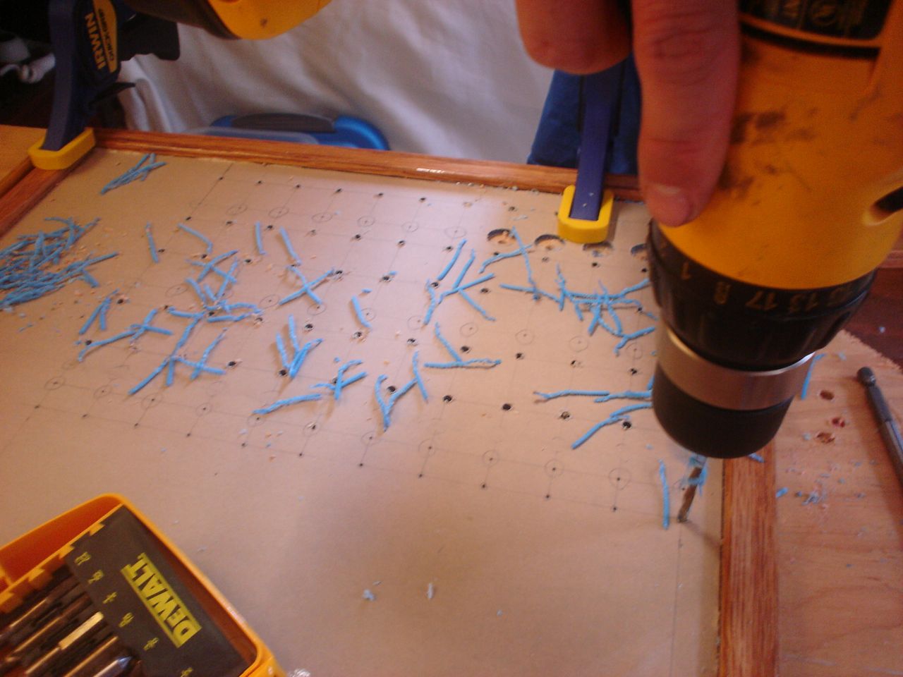
This was a hell of a job. First I’ll describe the original state of the panel. The panel was set back 4 inches in the space, behind a 3 inch vertical piece of trim. The panel was hinged at the bottom, so that when it folds down it hits the piece of trim, preventing it from opening less than halfway. Inside the panel, all of the negative wiring was piled up on a single stud, with over 16 terminals stacked on top of each other, all corroding. A handful of wires had pulled out of the terminals and were hanging loose in the compartment, only a few inches away from the hot stud. It was unorganized, impossible to access and work on it, and a serious fire hazard. I took out the old panel and cut out the trim so that the new panel could be mounted at the face of the compartment (rather than 4″ recessed). I constructed a new panel out of plexiglass from TAP plastics, laboriously drilling all the holes to accomodate the circuit breakers. I put a piece of hardwood trip around the outside (coated with penetrating epoxy) and used a long piano hinge to mount it. I used all of the old breakers from the old panel. To make the common, hot side of the circuit breakers, I bought a strip of solid copper from McmasterCarr, and drilled out holes to match the location of the circuit breakers. I bought tiny little screws from bowline and screwed the common hot side of each breaker flat against the copper bus bar. I ran 0 gauge hot and negative cables to the compartment, mounting all the negative to the right and all the hot to the left. The 0 gauge hot supply runs to a stud, and 3-4 gauge jumper cables connect from this stud to each of the copper bus bars on the back of the panel (there are three rows of breakers). I mounted three terminal blocks on the left side of the compartment, to mirror the three rows of circuit breakers. I used short jumpers of 12 gauge wire in as many different colors as I could find to make the connections from the circuit breakers to the terminal blocks. These short jumpers are bundled into spiral wrap to tame them. All of the negative wiring runs to a dedicated spot (very few stacked terminals) on two ample sized negative bus bars. The wiring remains loose in the compartment behind the panel, and looks completely disorganized. But there’s plenty of space and it is simple to trace wiring. I am concerned that if I bundle the wiring all up to make it look pretty, it will only make it more difficult to trace wiring.


")


We have about 6 120V outlets on the boat, that are powered either by shore power (when we are plugged in at the dock) or by our inverter running off the boat batteries (when we’re not).
GFCI outlets are the ones with a “test” and “reset” button in between the two plugs. GFCI stands for “ground fault current interrupt”. Here’s an extremely abbreviated explanation of what it does: it measures the current in and the current out, and if they don’t match, it trips. If you stick your finger in the outlet, some of the “current in” doesn’t make it to the “current out”, rather it takes a route through your body to get back to ground. The GFCI senses that current is going elsewhere, and trips.
GFCIs do not completely eliminate the risk of electrocution: they do not trip instantaneously (though they do operate very fast) and so during the millisecond that it takes for the GFCI to trip, you may have got enough of a dose to kill you. They do, however, significantly increase the protection and safety.
You can get them from home depot–I think they’re about $7 apiece (not including the box to mount them in and the plate to cover the front).
The GFCI outlets were bulkier than the old outlets, so I had to cut out the mounting hole a little bit on every one (wouldn’t expect any less frustration from a boat project).


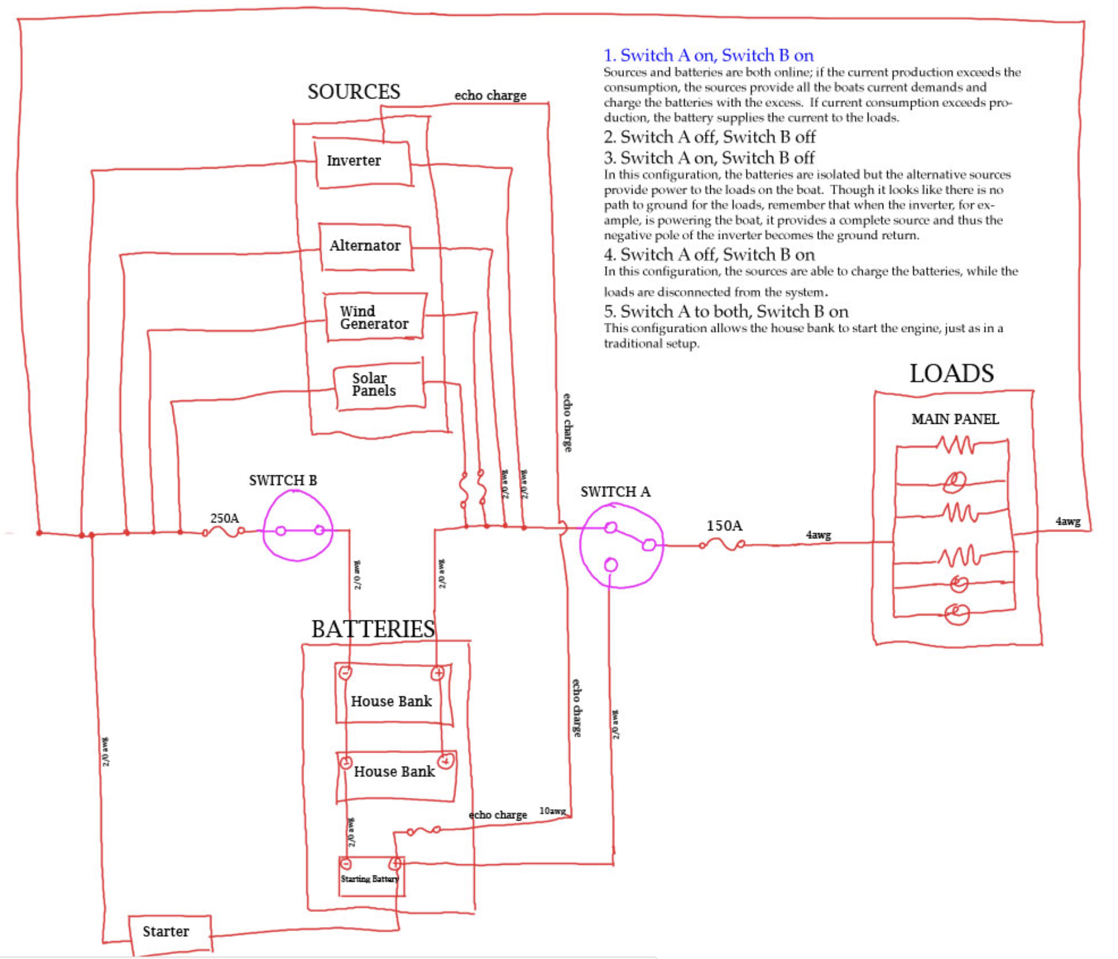
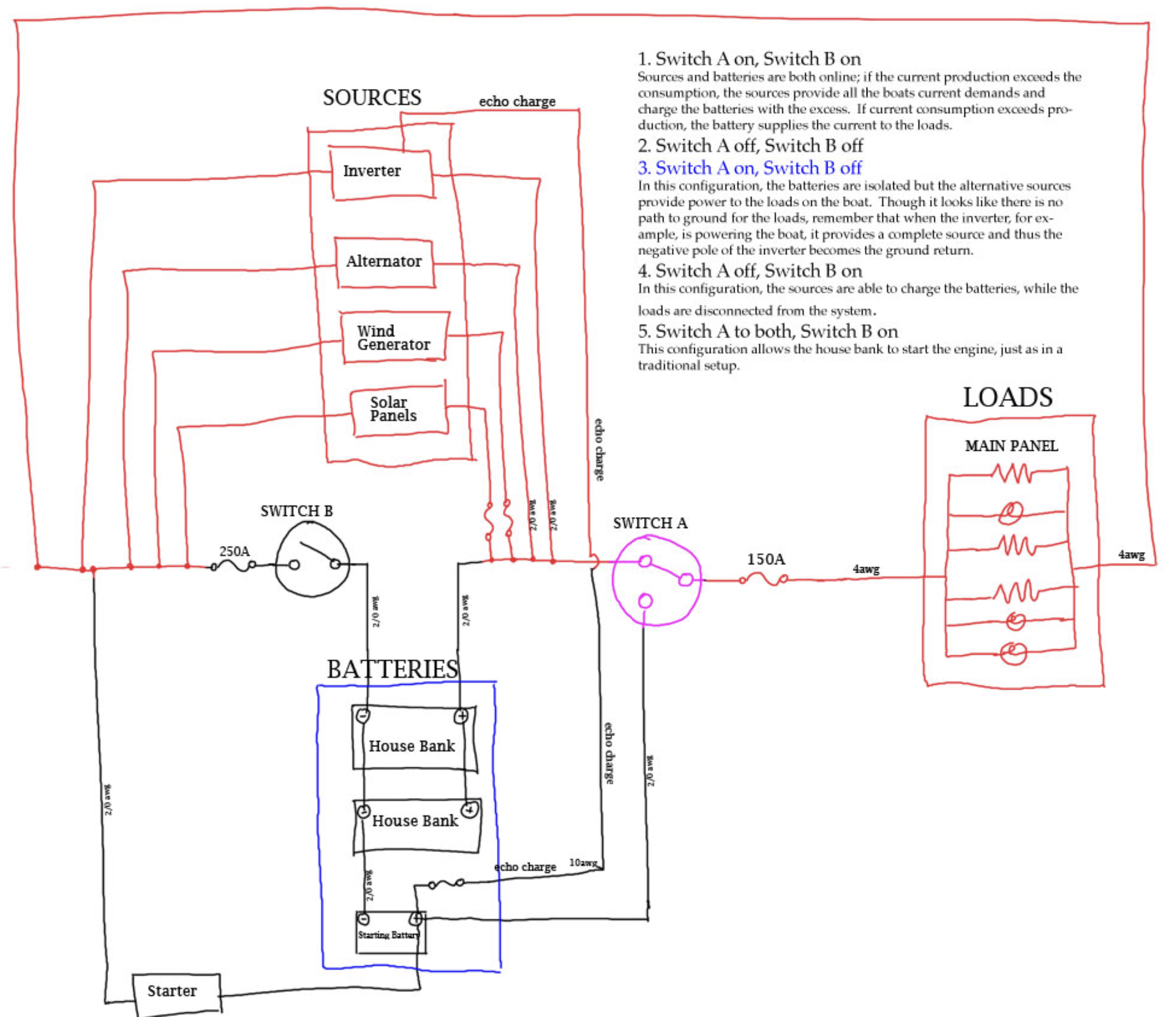
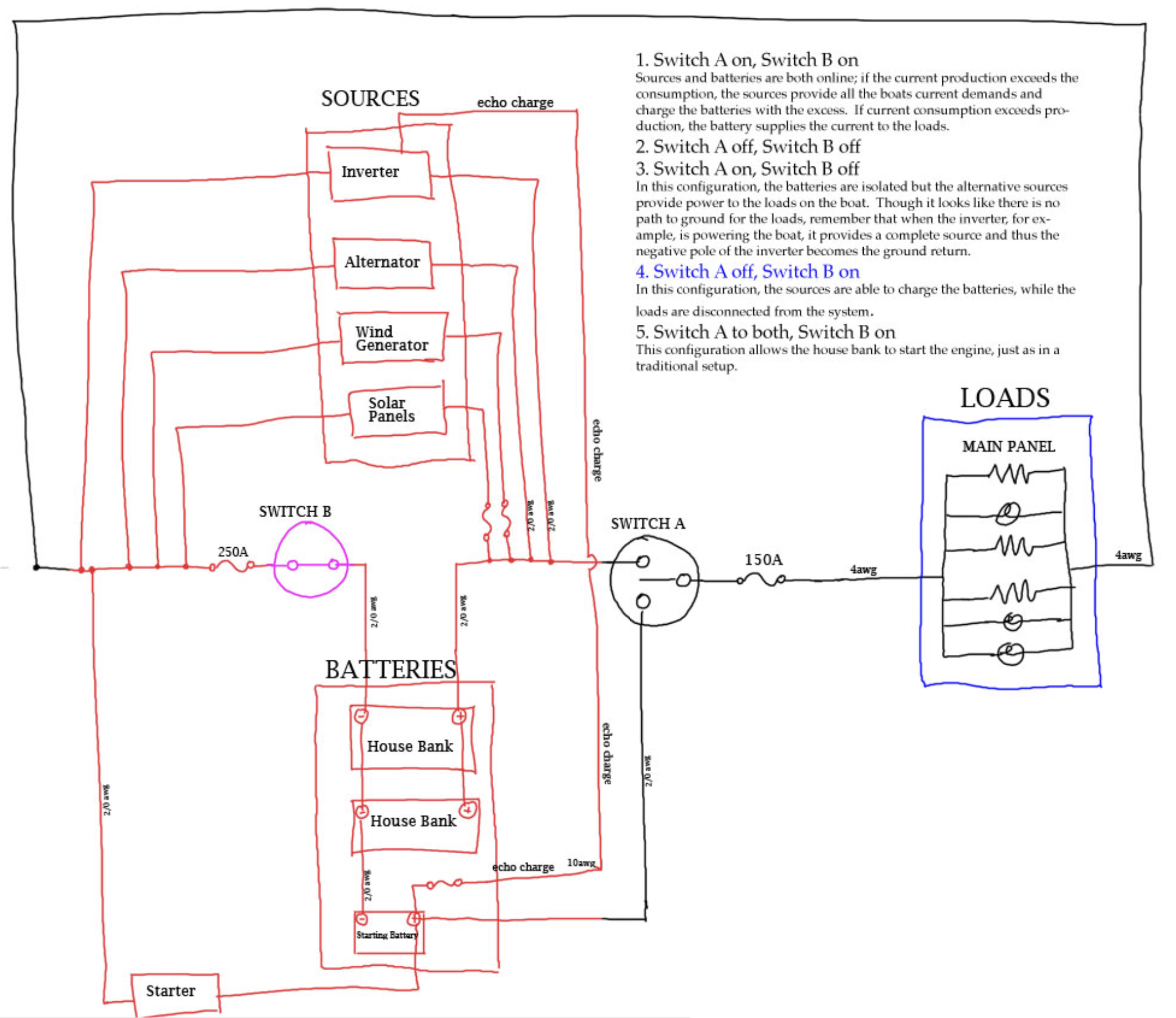
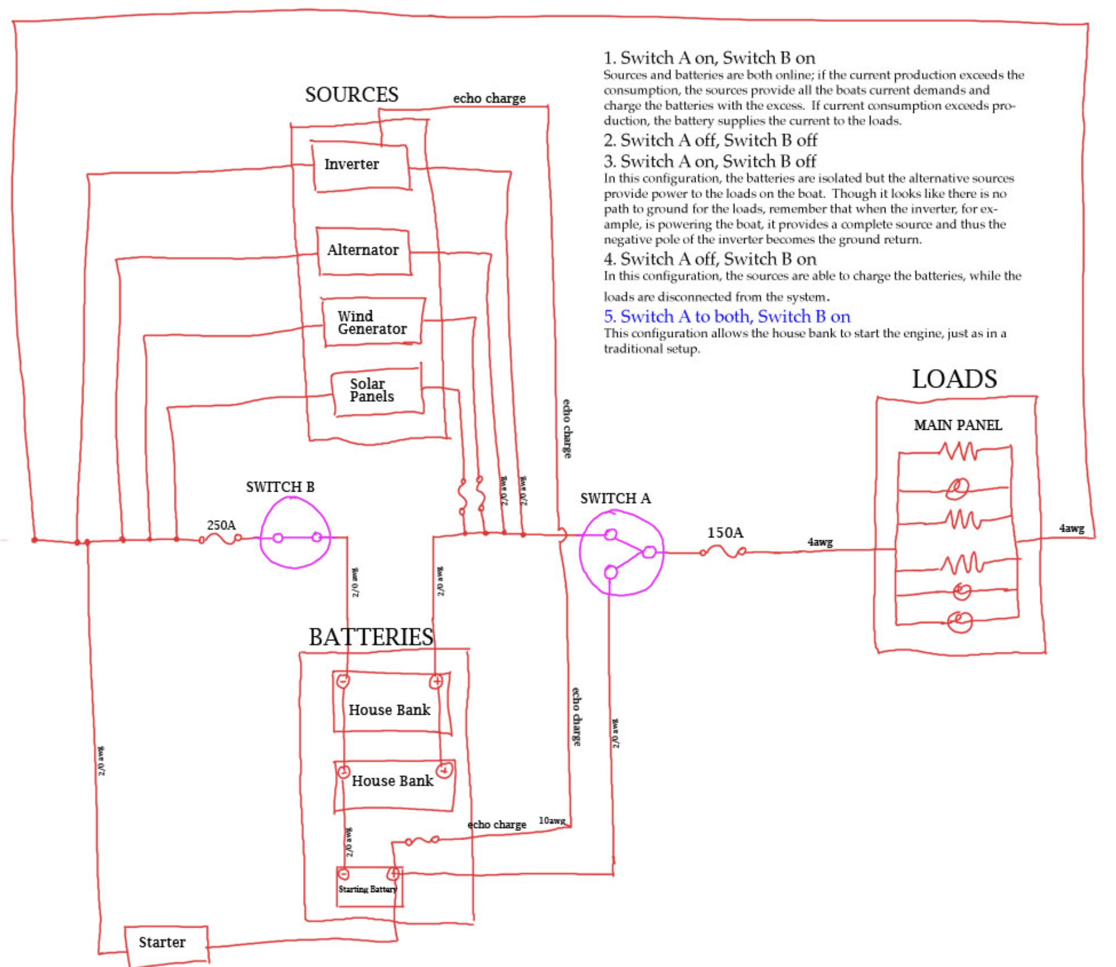
I made a diagram to show the basics of our setup. Hot wiring is red for the blue highlighted option in the list.
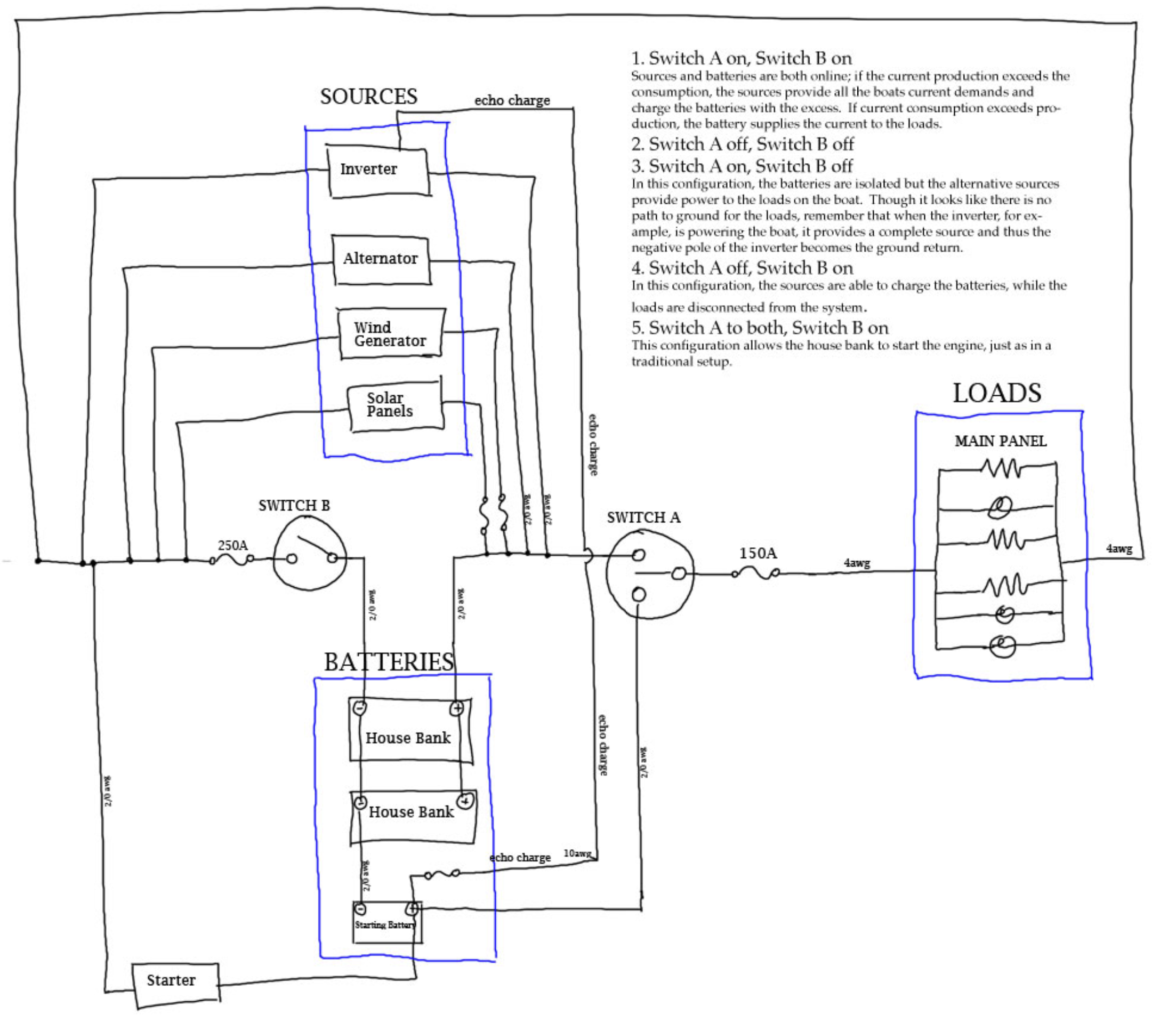
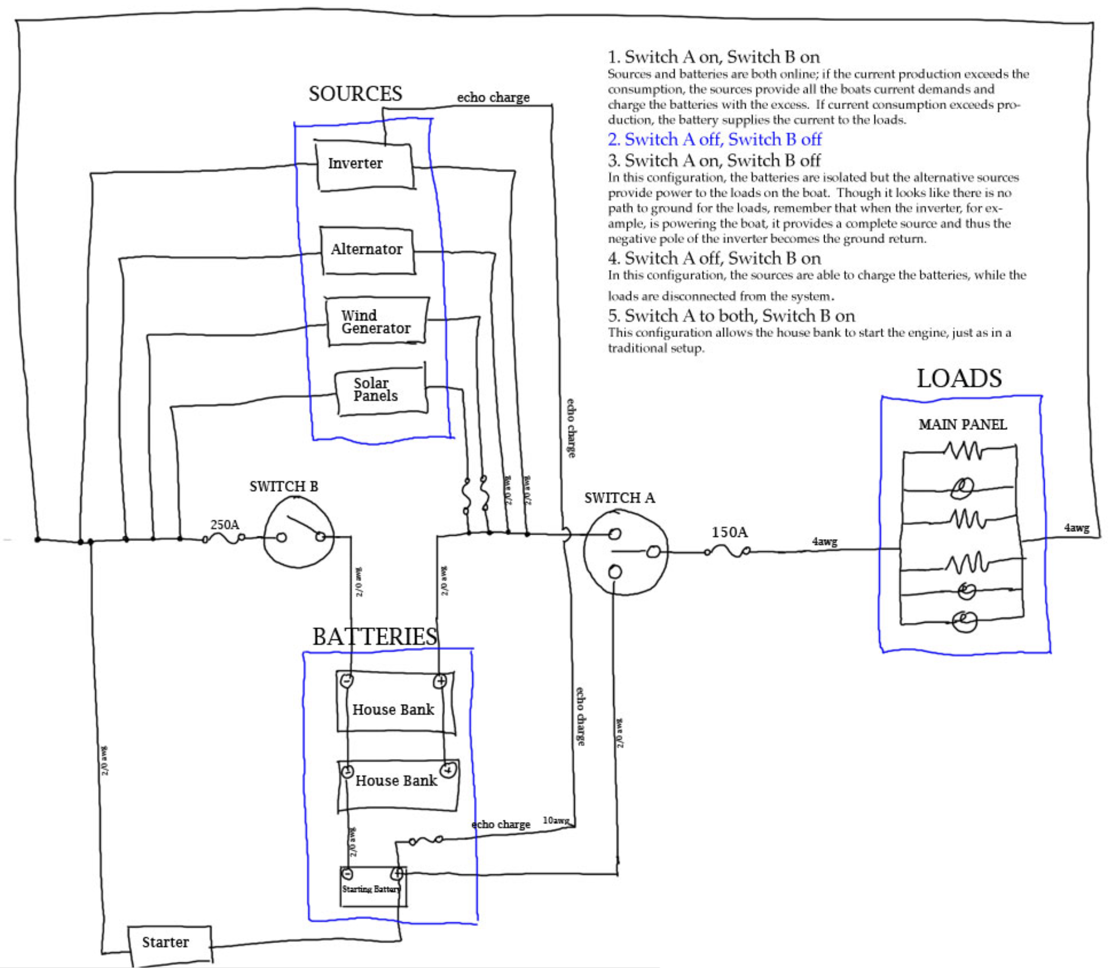
The traditionally espoused sailboat wiring setup is not ideal for a sailboat that incorporates multiple charging sources. The traditional setup uses two identical house battery banks and a single battery isolation switch.
The ideal setup uses a large deep-cycle high-capacity house bank and a small, inexpensive starting battery. The reason we use two battery banks on a sailboat is so that we always have a charged battery that can be used to start the engine. Identical house banks are an inefficient and expensive way to accomplish this goal. Prior to the existence of efficient and affordable series regulators, the double house bank setup made more sense. Now, we can use a $130 Xantrex Echo charger to siphon charge off of the house bank to the starting battery, with no danger of the starting battery becoming accidentally discharged.
The ideal setup uses two isolation switches.
These are the goals:
1) Ability to isolate current sinks from the batteries with a switch. Ability to isolate current sources from the batteries with a switch. Ability to isolate current sources from current sinks with a switch.
I was working on the electrical system with the main battery switch turned off, and was astounded to find that the lights (and everything else on the boat) still turned on. I realized that the Freedom Inverter, plugged into shore power, was acting as a transformer to supply 12V to the boat even without the batteries in the system (the inverter is on the downstream side of main switch). I considered moving the inverter to the upstream side of the main switch, but then I realized that I wouldn’t be able to switch the inverter out of the system–it would be constantly connected to the batteries. The same reasoning holds true for other sources of current as well, including the alternator, the PV panels, and the wind generator. I do not want those things constantly connected, without a quick way (a switch) to remove them from the system when leaving the boat.
The solution is to have two switches rather than the traditional single switch. By installing the second switch in the ground return instead of the supply side, we have isolated both house and starting batteries at the same time. (similarly, by installing the 200A fuse in the return line we protect the 2/0 wiring with just one fuse, instead of one in each of the batteries + side.
2) Separate house bank and starting battery.
This is the most efficient and cost effective way to maximize capacity available for regular usage while maintaining a backup way to start the engine.
The starting bank is charged with the Xantrex echo charger; the Freedom Marine 20 inverter has one built in that will come online regardless of charging source (not just the AC). I ran the starter hot to the other spot on the main switch, so that in the event that the starting battery fails, the house bank can be used to start the engine.
3) Protect all wiring with as few fuses as necessary.
To this end, I have inserted the fuse for the 2/0 cable in the ground return rather than the positive side. If I had put it in the positive side, I would have needed separate ones for the house and starting batteries.
. . . from blog writing, not from boat work!
Apologies for not updating the site in so long. I ran out of memory at my hosting provider, or something like that, and I was too lazy/busy to fix it for the past few months. Anyway, we’re back in business, and I have a long backlog of work to add to the log. It will all appear to take place in the next week, because I’m not going to bother backdating it.
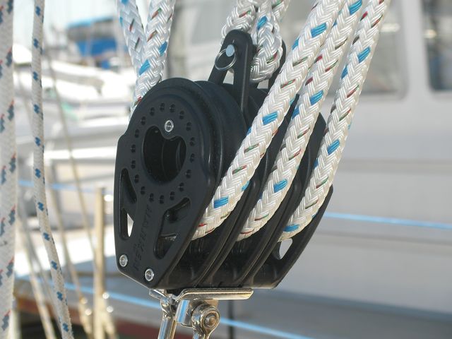
The old ones were corroded and friction-filled. When we went to remove them, most of the machine screws holding them in place sheered off (and the resultant bits were a bitch to remove). The new blocks are high-load and expensive.
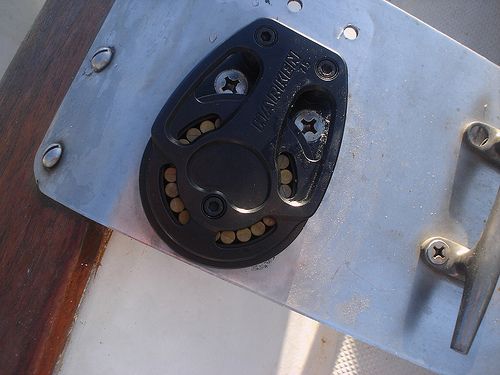
The old mainsheet setup wasn’t good enough for me. There wasn’t enough puchase power to sheet and ease the main by hand, without the use of a winch. I want to be able to do it much more quickly than the winch setup will allow. Also, the old blocks were worn out (high friction).
We spent a small fortune on seven new high-tech blocks to fix the system, and it works like a dream. It can be sheeted in and out by hand even in heavy wind, and it makes the job of trimming the main quick and pleasant–which incidentally means that it gets adjusted and fine-tuned much more frequently.
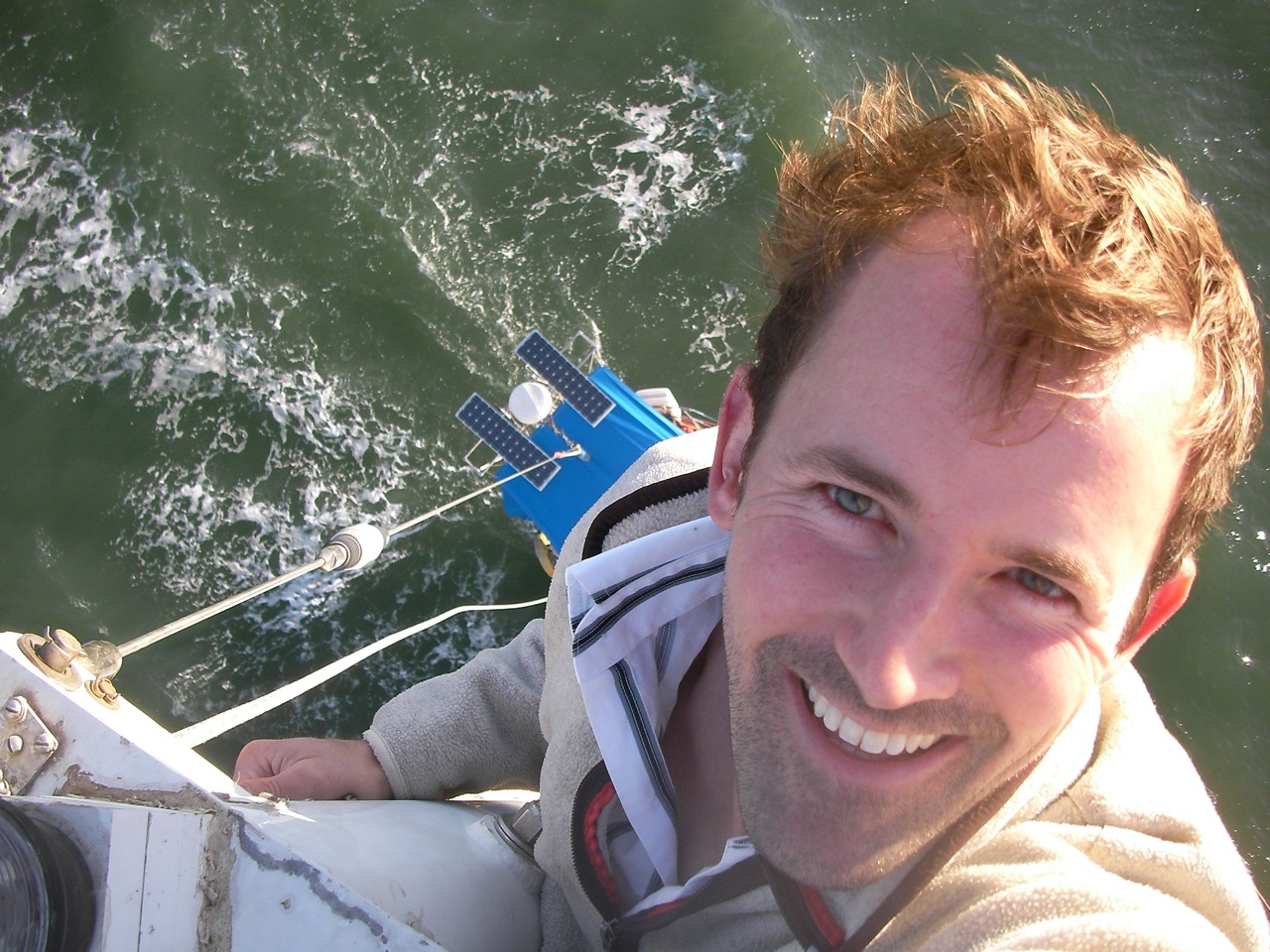
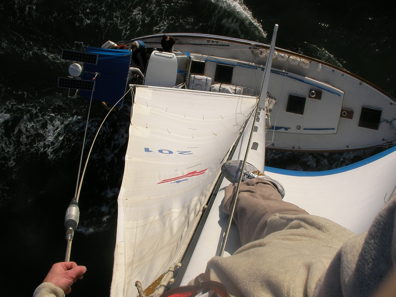
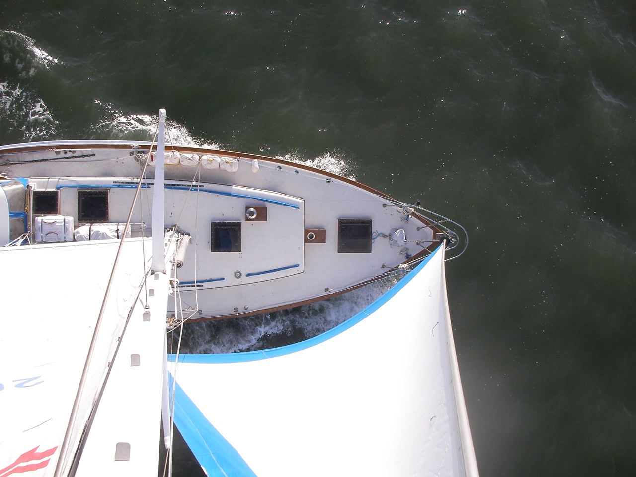
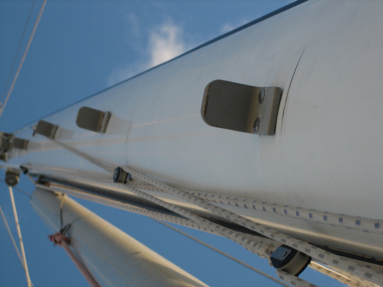
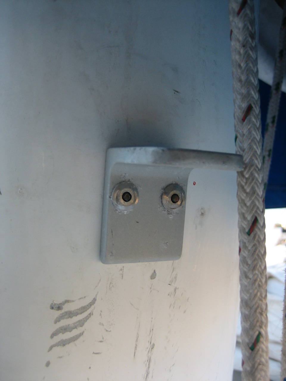
I designed some super simple mast steps for us. I didn’t like the popular commercially available options: the folding steps are too much of a hassle, too complicated, and too much money, and the stirrup kind are too large and bulky (fouling lines) and also too expensive. All three of us are climbers, so we wanted just a small “L” just large enough for secure purchase, with rounded corners to let lines easily pass by. I asked a sailing machinist John Ryan for advice and help, and got a ton. John Ryan graciously improved the design and fabricated them, far more perfectly than we ever expected (from choice of aluminum alloy, to the tumbling to remove all edges, to the clear anodize finish, and even the rivets, drill bit size, and pattern to follow for drilling the holes!), and jonny installed them. Well they’re all in now and the end result is stellar–everything that we wanted. It is fast and easy to climb to the top of the mast, fun even. Everyone who sees them wants their own, too!